

Page 1
MANUFACTURING QUALITY LAWN CARE EQUIPMENT SINCE 1945
Owner’s
Manual
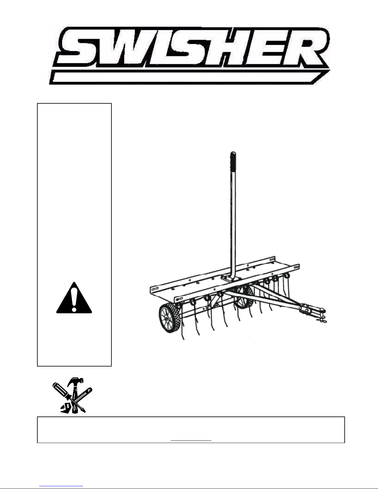
DT-40
40” Tine De-thatcher
IMPORTANT
Read and follow all
Safety Precautions
and Instructions
Before Operating this
Equipment.
1602 CORPORATE DRIVE, PO BOX 67 , WARRENSBURG, MISSOURI 64093
11781 REV. 05-340
Made In CHINA
PH 660. 747. 8183 FAX 660. 747. 8650
swisherinc.com
Page 2

LIMITED WARRANTY
The manufacturer’s warranty to the original consumer purchaser is: This product is free
from defects in materials and workmanship for a period of One (1) year from the date of
purchase by the original consumer purchaser. We will repair or replace, at our discretion,
parts found to be defective due to materials or workmanship. This warranty is subject to the
following limitations and exclusions:
1) Commercial Use This product is not intended for commercial use and
carries no commercial warranty.
2) Limitation This warranty applies only to products which have been
properly assembled, adjusted, and operated in accordance
with the instructions contained within this manual. This
warranty does not apply to any product of Swisher Mower
Co. Inc., that has been subject to alteration, misuse, abuse,
improper assembly or installation, shipping damage, or to
normal wear of the product.
3) Exclusions Excluded from this warranty are normal wear, normal
adjustments, and normal maintenance.
In the event you have a claim under this warranty, you must return the product to an
authorized service dealer. All transportation charges, damage, or loss incurred during
transportation of parts submitted for replacement or repair under this warranty shall be borne
by the purchaser. Should you have any questions concerning this warranty, please contact
us toll-free at 1-800-222-8183. The model number, serial number, date of purchase, and the
name of the authorized Swisher dealer from whom you purchased the mower will be needed
before any warranty claim can be processed.
THIS WARRANTY DOES NOT APPLY TO ANY INCIDENTAL OR CONSEQUENTIAL
DAMAGES AND ANY IMPLIED WARRANTIES ARE LIMITED TO THE SAME TIME
PERIODS STATED HEREIN FOR ALL EXPRESSED WARRANTIES. Some states do not
allow the limitation of consequential damages or limitations on how long an implied warranty
may last, so the above limitations or exclusions may not apply to you. This warranty gives
you specific legal rights and you may have other rights, which vary from state-to-state. This is
a limited warranty as defined by the Magnuson-Moss Act of 1975.
2
2
Page 3
RULES FOR SAFE OPERATIONS
perly or if the user
nstructions before attempting to assemble or
know how to operate the vehicle before using
attachment, and do not allow adults to operate
ear substantial foot wear
gine at low speed, and gradually increase speed
tachment of this equipment. Be aware of
cle owner's manual concerning safe operation
terrain, along creeks and ditches and on
Remember, any power equipment can cause injury if operated impro
does not understand how to operate the equipment.
Exercise caution at all times when using power equipment.
1. Read this owners manual carefully for operating and service i
operate this equipment. Be thoroughly familiar with the proper use of this equipment.
2. Read the vehicle owners manual and vehicle safety rules, and
this equipment.
3. Never allow children to operate the tractor or de-thatcher
without proper instructions.
4. This de-thatcher attachment has sharp tine points. Always handle with care and w
when operating this de-thatcher.
5. Do not allow anyone to ride or sit on de-thatcher attachment frame or on towing vehicle.
6. Keep the area of operation clear of all persons, particularly small children and also pets.
7. Always begin with the transmission in first (low) gear and en
as conditions permit.
8. The vehicle braking and stability may be affected with the at
changing conditions on slopes. Refer to safety rules in the vehi
on slopes.
STAY OFF OF STEEP SLOPES.
9. Always operate up and down a slope, never across the face of a slope.
10. This equipment should be operated at reduced speed on rough
hillsides, to prevent tipping and loss of control. Do not drive too close to a creek or a ditch.
11. Do not tow this equipment on a highway or any other public thoroughfare.
12. Follow the maintenance instructions as outlined in this owners manual.
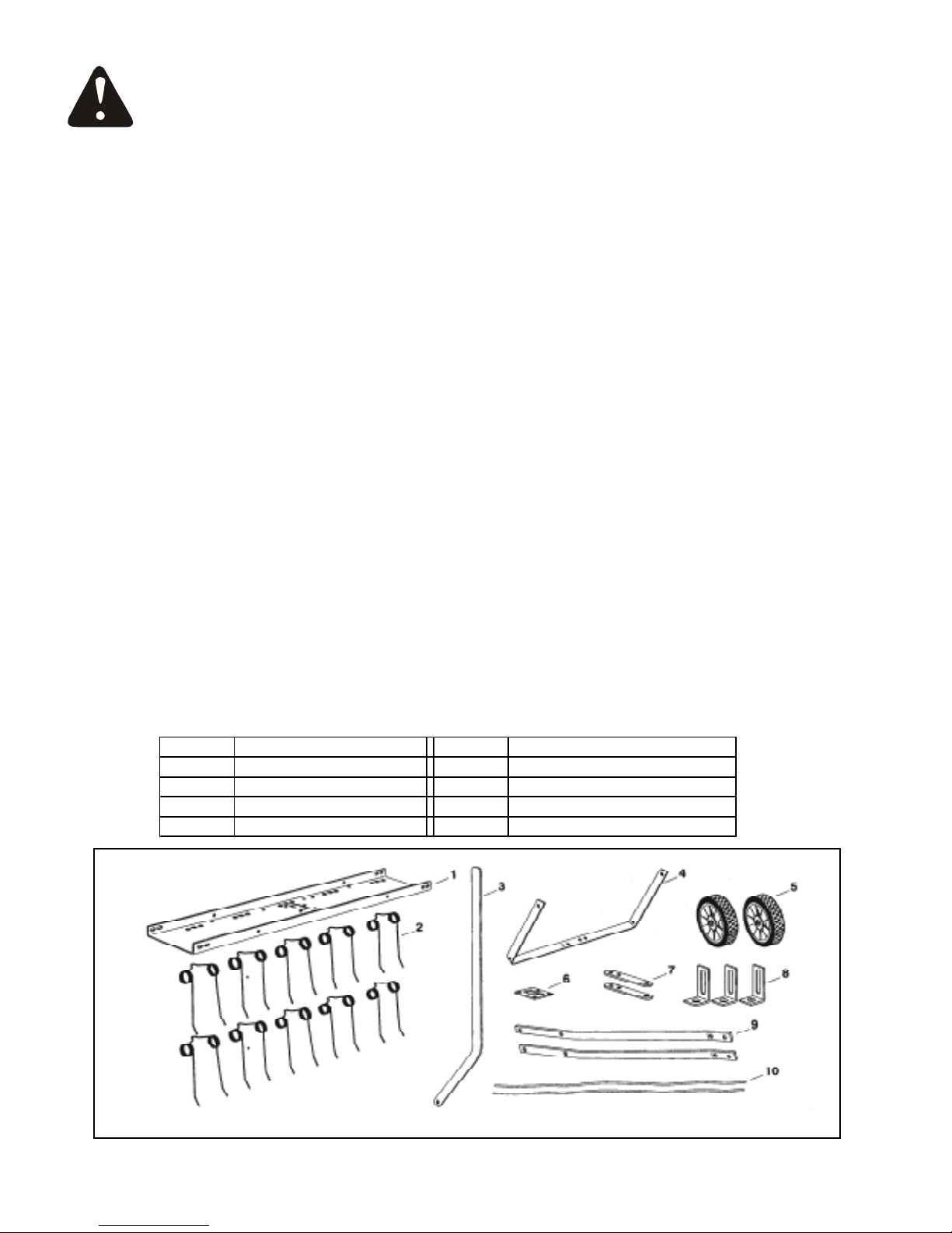
LOOSE PARTS IN CARTON
1 Tine Shield 6 Lift Plate
2 Spring Tines (10) 7 Hitch Brackets (2)
3 Lift Handle 8 Hitch Arm Mount Brackets (3)
4 Axle Brachet 9 Hitch Mount Arms (2)
5 Wheels (2) 10 Spring Alignment Wires (2)
3
Page 4

HARDWARE PACK
TOOLS REQUIRED
FOR ASSEMBLY
Key Qty Description Key Qty Description
A 2 Shoulder Bolt H 14 Hex Nut M8
B 2 Hex Bolt M8 X 50 I 19 Hex Lock Nut M8
C 2 Hex Bolt M8 X 30 J 2 Hex Lock Nut M10
D 15 Hex Bolt M8 X 20 K 14 Lock W asher
E 14 Carriage Bolt M8 X 25 L 10 Flat W asher
F 1 Hitch Pin (Dia 10) M 4 Angle Bracket
G 1 Hair Cotter Pin (Dia 3) N 1 Handle Grip
(2) 1/2" wrenches
(1) 9/16" wrench
(1) 3/4" wrench or adjustable wrench
(1) Pliers
Assembly Instruction
Before assembling the de-thatcher, lay out all of the
parts and hardware as shown on the previous pages.
The 40" de-thatcher is shown in the following
drawings. The assembly of the 40" and 48" is the same
except as noted in the instructions.
2. Turn the tine shield upside down. See figure 2.
3. Assemble two (tall) hitch arm mount brackets and
two (short) angle brackets to the bottom of the tine
shield. Fasten the brackets to the four round holes
at the rear of the tine shield using four M8x20 hex
bolts and M8 hex lock nuts. Do not tighten yet.
See figure 2.
4. Assemble two angle brackets to the round holes
in the bottom of the tine shield at the front. Use two
M8x20 hex bolts and M8 hex lock nuts. Do not
tighten yet. See figure 2.
1. Assemble the lift plate to the top of the tine shield
using four M8x20 hex bolts and M8 hex lock nuts
as shown in figure 1. Tighten.
LIFT PLATE M8X20
FIGURE 1
HEX
BOLT
M8 HEX
LOCK NUT
HITCH ARM
MOUNT BRACKET
ANGLE
BRACKET
4
FIGURE 2
M8 HEX
LOCK NUT
ANGLE
BRACKET
M8X20
HEX BOLT
Page 5

5. Fasten the hitch mount arms to the outside of the
FIGURE 7
5
angle brackets at the front of the tine shield. Use
two M8x20 hex bolts and M8 hex lock nuts.
Tighten and then loosen the nuts slightly.
See figure 3.
6. Fasten the hitch mount arms to the outside of the
hitch arm mount brackets at the rear of the tine
shield. Use two M8x25 carriage bolts, M8 lock
washers and M8 hex nuts. Do not tighten yet.
See figure 3
FIGURE 3
7. Assemble the front ends of the hitch mount arms
together using two M8x30 hex bolts and M8 hex
lock nuts. Do not tighten yet. See figure 4.
8. Assemble the hitch brackets to the top and bottom
of the hitch mount arms using two M8x50 hex bolts
and M8 hex lock nuts. Do not tighten yet. See
figure 4.
9.Assemble the Ф10 hitch pin through the hitch
brackets and secure it with a Ф3 hair cotter pin.
See figure 4.
11. Assemble the axle bracket on the outside of the
angle brackets using two M8x20 hex bolts and M8
hex lock nuts. The ends of the axle bracket must
point as shown in figure 5. Tighten and then
loosen the bolts and nuts slightly.
HITCH MOUNT ARMS
FIGURE 5
12. Assemble the wheels to the axle bracket using two
shoulder bolts and two M10 hex lock nuts. Tighten.
See figure 6.
FIGURE 4
10. Tighten the bolts and nuts assembled in step 8.
Tighten the bolts and nuts assembled in step 7.
Tighten the bolts and nuts assembled in step 3.
Tighten the bolts and nuts assembled in step 4.
Tighten and then loosen slightly the bolts and
nuts assembled in step 5.
Tighten the bolts and nuts assembled in step 6.
FIGURE 6
13. Fasten ten spring tines to the square holes in the
bottom of the tine shield. Use a M8x30 carriage
bolt, Ф8 flat washer M8 lock washer and M8 hex
nut for each spring tine. Tighten. See figure 7.
NOTE: Spring tines must seat between dimples.
Page 6

14. Assemble the spring align wires through the front
6
and rear rows of spring tines, passing the wires in
between the hitch mount arms and the tine shield.
Bend the ends of the wires to secure them. See
figure 8.
FIGURE 8
15. Assemble a hitch arm mount bracket to the axle
bracket using two M8x25 carriage bolts, M8 lock
washers and M8 hex nuts. Do not tighten yet.
See figure 9.
16. Insert the lift handle down through the tine shield.
Attach it to the just assembled hitch arm mount
bracket using M8x20 hex bolt and a M8 hex lock
nut. Tighten. See figure 9.
17. Position the hitch arm mount bracket so that there
is side tension on the lift handle when it is locked
in the up position. Tighten the nuts. See figure 9.
18. Assemble the grip onto the end of the lift handle.
See figure 9.
OPERATION / ADJUSTMENT
Regular removal of thatch is critical to maintenance of
a healthy lawn. Thatch is a layer of stems, clippings,
runners, roots and leaves that have not decayed.
Excessive thatch prevents air, water and fertilizer
from reaching the roots. The de-thatcher effectively
dislodges excessive thatch from your lawn. Read
these instructions to help avoid improper adjustment
and operation.
Proper adjustment of the tine shield and spring
tines is important for effective performance. Refer
to the following steps for the proper adjustment
before operating the de-thatcher.
1. Move the towing vehicle onto a level surface, such
as a driveway or garage floor and attach the tine
de-thatcher to the vehicle hitch. See figure 10.
2.To adjust the spring tine shield, lower the dethatcher into operating position using the lift
handle. Loosen the two hex nuts and carriage
bolts which fasten the rear of the hitch mount arms
to the hitch arm mount brackets. Adjust the tine
shield until it is level and both the front and rear
spring tines are in contact with the ground. Retighten the hex nuts. See figure 10.
FIGURE 9
FIGURE 10
3. Vary the vehicle's forward speed until the best
de-thatching action is achieved.
4. For best results, use a crisscross pattern on your
lawn.
Page 7

5. If the de-thatcher appears to be "jumping" during use, then
extra weight should be added to the tine shield. In most
conditions extra weight will be needed. Concrete patio blocks
are recommended for weight because of their low profile;
however any type of weight is suitable if it can be tied down to
the shield. Secure weight by using suitable binding material
such as rubber tie down straps or wire, fastening to the holes in
the shield flange.
See figure 11.
MAINTENANCE
1.Before each use check all nuts and bolts for tightness.
2. Lubricate wheels as needed.
3. If rust appears on the shield or spring tines, sand
lightly and coat with enamel paint.
4. Always store in a dry area, and coat exposed
metal with light oil when not in use.
FIGURE 11
Key Part No. Qty Description Key Part No. Qty Description
1 12208 3 Hitch Arm Mount Bracket 13 12220 2 Hex Lock Nut M10
2 12209 2 Hitch Bracket 14 NB275 10 Flat Washer M8
3 12210 10 Spring Tine 15 NB719 15 Hex Bolt M8 X 20
4 12211 2 Spring Alignment Wire 16 NB159 14 Lock Washer M8
5 12212 2 Wheel 17 NB718 14 Hex Nut M8
6 12213 1 Tine Shield 18 12221 19 Hex Lock Nut M8
7 12214 2 Hitch Mount Arm 19 12222 14 Carriage Bolt M8 X 25
8 12215 1 Lift Plate 20 12223 1 Handle Grip
9 12216 1 Axle Bracket 21 12224 2 Hex Bolt M8 X 50
10 12217 1 Lift Handle 22 NB232 2 Hex Bolt M8 X 30
11 12218 2 Shoulder Bolt 23 12225 1 Hitch Pin M8 Flat Hd.
12 12219 4 Angle Bracket 24 NB247 1 Hair Pin Dia 3
Page 8

MANUFACTURING QUALITY LAWN CARE EQUIPMENT SINCE 1945
Owner’s
Manual
DT-40
IMPORTANT
Read and follow all
Safety Precautions
and Instructions
Before Operating this
Equipment.
ATV & LAWN ACCESSORIES
WHEN ORDERING PARTS, PLEASE HAVE THE
FOLLOWING INORMATION AVAILABLE:
* PRODUCT – ________________
* SERIAL NUMBER - _______________
* MODEL NUMBER - _______________
TYPE - _______________
* PART NUMBER WITH PAINT CODE
* PART DESCRIPTION
TELEPHONE - 1-800-222-8183
FAX - 1-660-747-8650
SWISHER MOWER & MACHINE CO. INC.
SWISHER MOWER & MACHINE CO. INC.
SWISHER MOWER & MACHINE CO. INC.SWISHER MOWER & MACHINE CO. INC.
1602 CORPORATE DRIVE
P.O. BOX 67
WARRENSBURG, MO 64093
swisherinc.com
 Loading...