

Swingtec Fontan Series, Fontan Mobilstar M, Fontan Portastar S, Fontan Mobilstar E, Fontan Mobilstar ER Instruction Manual

Swingtec GmbH • Achener Weg 59 • 88316 Isny / Germany
Instruction Manual
Fontan Fuel-Driven ULV Aerosol Generators (Cold Fogging Aerosol
Applicators)
Fontan devices are provided with protective equipment and have been carefully tested before delivery.
We cannot be held liable for injuries to persons, damage to property and consequential damage if the device is not used
or operated in accordance with the provisions of this instruction manual. The instruction manual is included with every
device. In addition, a comprehensive manual in English, Spanish, French or German is included with every device.
All regulations that apply to petrol-driven devices must be heeded.
The following safety measures must be taken:
Use only clean containers for filling the fuel tank and the spraying tank.
When refilling fog liquid, always fill up the fuel tank at the same time.
The devices are started via an electronic ignition coil.
Persons with pacemakers may only start the devices after consulting a doctor.
Only start up devices that are free of defects and faults. Do not modify or remove protective devices.
The applicable legal regulations and specifications of the preparation manufacturer must be observed
when selecting and using chemical preparations and carrier substances.
Read, understand and heed the instruction manual
Never operate the device unattended
Wear protective clothing
Wear protective gloves
Wear respiratory protection
Wear safety goggles
Use hearing protection
Fire, ignition sources and smoking are prohibited when operating the device
Attention: hot surfaces
Residual amounts of fuel and fog liquid must be disposed of in accordance with the legal regulations.
Avoid reaching an explosive concentration when fogging combustible substances indoors. Safety limit:
output max. 3 l per 1000 m³.
Materials for extinguishing fires must be available.
Devices at operating temperature may not be transported in vehicles (fire hazard).
Prevent tipping over of the device during transport.
For questions, please contact your local supplier or Swingtec GmbH.
E-mail: info@swingtec.de
Edition: 25/01/18
1
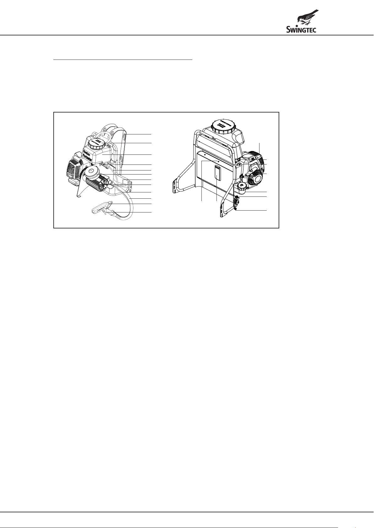
Fontan Portastar S - Commissioning
The Fontan Portastar S is used outdoors for the control of pests, mosquitoes and desert locust as well as for plant
protection measures in plantations.
The device uses the ULV (ultra low volume) process and produces a dense aerosol fog with a VMD (volume median
diameter) droplet spectrum of <30 μm with all standard nozzles.
Depending on the wind conditions, the fog can drift 50 m or more.
The spray gun (8) must be attached to the provided strap on the device frame and secured during transport.
11
1
10
2
3
4
5
12
6
4
7
8
9
20
18
13
14
16
19
15
17
1 Spraying tank cap with vent hole 11 Carrying strap
2 Spraying tank 12 Waist strap
3 Fog liquid valve 13 Decompression valve
4 Solution line 14 Primer pump
5 Air filter (compressor) 15 Engine switch (ON/OFF)
6 Compressor 16 Manual recoil starter
7 Air hose 17 Throttle lever
8 Spray gun
Dosing nozzle 45 already installed *) **)
18 Opening in the carrying frame to operate the choke
(choke is not visible)
9 Spray lever 19 Fuel tank
10 Engine 20 Screw with ring, access to the air filter (engine)
*) The remaining standard dosing nozzles are located in the tool bag
**) Nozzle change and standard nozzle set with flow rates on page 3.
Device start
• Fill the spraying tank (2). Use the chemical funnel with strainer (large, standard accessory).
• Fill the fuel tank (19). Use the fuel funnel with strainer (small, standard accessory).
• Fuel: Two-stroke mixture, regular petrol station fuel, lead-free or leaded, mixed with quality 2-stroke oil.
Oil-petrol mixture ratio 1:50.
• Set the engine switch (15) to the “ON” position.
• Actuate the primer pump (14) repeatedly (fuel supply to the carburettor).
• Push the choke lever (18) upwards.
• Push the throttle lever (17) all the way down.
• Press the decompression valve (13).
• Forcefully and repeatedly (if necessary) pull the manual recoil starter (16) until the engine starts briefly. Then push
the choke lever down.
• Pull the manual recoil starter again until the engine is running.
• Open the fog liquid valve (3) (lever down).
• Put the device on your back and adjust the carrying straps (11) and waist strap (12).
• Move the throttle lever (17) upwards to the maximum position (full throttle position).
Only in this position does the device work properly and meet the specifications regarding spray output and droplet
quality.
(The full throttle position is fixed and below the maximum engine power).
• Pull the spray lever (9) on the spray gun. The device fogs. The fogging function stops when you let go of the spray
lever.
25/01/18
2

Device stop
• Let go of the spray lever. The device stops fogging.
• Set the throttle lever (17) to the bottom position (idle position).
• Set the engine switch (15) to the “OFF” position. The engine shuts off.
• Take the device off your back.
• Close the fog liquid valve (3) (lever upwards).
Switching off
• Check the air filter (compressor) (5).
Make sure the air filter is not contaminated with deposits or saturated with moisture.
This could damage the compressor and possibly also the engine. Minor deposits on the air filter can be brushed off
or removed with compressed air.
Heavily contaminated or wet air filters must be replaced.
• Regularly check the filter element (carburettor). This is especially important if the device is operated in a dusty
environment.
d
a
a Housing screw
b Filter housing
c Filter element
d Carburettor
c
b
• Manually unscrew the screw with the ring (20) and move the engine/compressor slightly forward sideways.
• Loosen the filter housing (b) by turning the housing screw (a) a quarter turn counter clockwise and take off the
housing.
• Remove the filter element (c) from the carburettor (d).
• Clean the filter element by tapping on it, or use compressed air if necessary.
• Replace the filter element if it is damaged or heavily contaminated.
• The air filter is assembled in reverse order:
Insert the filter element in the carburettor; assemble the filter housing and fix it with a housing screw (quarter turn
clockwise); tilt the engine/compressor backwards sideways and fasten with the screw and ring.
Changing the dosing nozzles
The dosing nozzles are mounted in the device's spray gun:
a
e
a Atomiser nozzle with mounted dosing
b
c
nozzle
b Dosing nozzle
c Atomiser nozzle
d Allen key 3 mm, standard accessory
e Screwdriver, standard accessory
d
• Unscrew the atomiser nozzle with mounted dosing nozzle (a) with the Allen key (d).
• Unscrew the dosing nozzle (b) with the screwdriver (c), using the Allen key as a hold.
• Screw the new dosing nozzle into the atomiser nozzle. Use the screwdriver and Allen key as a hold.
• Screw the atomiser nozzle with mounted dosing nozzle into the spraying device using the Allen key.
Standard stainless steel dosing nozzles with nozzle designation and flow rates
at fixed, full engine speed (measured with water):
30 1 l/h
45 2 l/h
58 3 l/h
84 6 l/h
without nozzle 17 l/h
Dosing nozzle 68, flow rate 4 l/h available as optional accessory
3

Fontan Mobilstar M, Fontan Mobilstar E, Fontan Mobilstar ER
Commissioning - generally applies to all device variants M, E and ER
The Fontan Mobilstar “M”, “E” and “ER” models are loaded onto vehicles and used outdoors for the control of pests,
mosquitoes and desert locust as well as for plant protection measures in plantations.
13
12
6
4
5
7
9
11
10
The devices can be used with the ULV (ultra low volume), ULV-Plus and LV (low volume) spraying processes.
Spraying process Spray output
ULV 5 - 49 l/h 85% < 20 μm 100 - 200 m
ULV-Plus 50 - 100 l/h 80% < 40 μm up to 100 m
LV 5 - 100 l/h VMD (volume median diameter)
8
14
(measured with water)
3
Droplet spectrum Fog drift
75 - 100 μm
1 Spray heads
2 Bar (vertical adjustment of the spray heads)
3 Clamping lever (fixation of the bar)
4 Control unit / remote control
1
5 Emergency shutdown engine
6 Ignition key
2
7 Engine start button
8 Fuel tank
9 Carry handle
10 Door
15
(access to the rinsing fluid container)
11 Rinsing fluid container
16
12 Manual recoil starter
13 Choke
14 Dry cell battery 12 V / 36 Ah (optional
accessory)
15 Air filter (compressor)
16 Solution line
depending on wind
conditions
20 - 50 m (drift-reduced)
• Check the engine's oil level.
• Install and connect the battery (12) (observe the polarity +/-).
• Fill the fuel tank (7) (regular petrol, unleaded or leaded).
Use the fuel funnel with strainer (small, standard accessory).
• Fill the spraying tank. Use the chemical funnel with strainer (large, standard accessory).
• Fill the rinsing tank with a suitable cleaning fluid.
Use the chemical funnel with strainer (large).
Use water if watery fog liquids are used, and diesel oil for oily fog liquids.
• Set the spray bar (2) to the required height and fix it with the clamping lever (3).
• Adjust the spray heads (1) (ULV / ULV-Plus and LV)
a
e
d
c
b
Loosen the cap nuts (a) and set the adjusting plate (b) to ULV or LV spraying with the setting pin (c).
Fix the setting with the cap nuts (a).
a Cap nut
b Setting plate with setting pin (ULV / LV)
c Setting pin
d ULV / ULV-Plus setting
e LV setting
4
Decommissioning
• The stainless steel spraying tank (see below) is emptied by connecting the tank emptying device (see below [g]) to
the quick coupling (e). The cap of the spraying tank (a) must be open.
• When using Swingtec's polyethylene spraying tank for the Fontan Mobilstar E and ER models, the tank-emptying
device is also connected to the solution line's quick coupling. The cap of the spraying tank must be open.
Polyethylene tanks (Fontan Mobilstar E and ER) are cleaned via the filling opening, and stainless steel tanks
through the cleaning opening (f).
• Disconnect the battery (14).
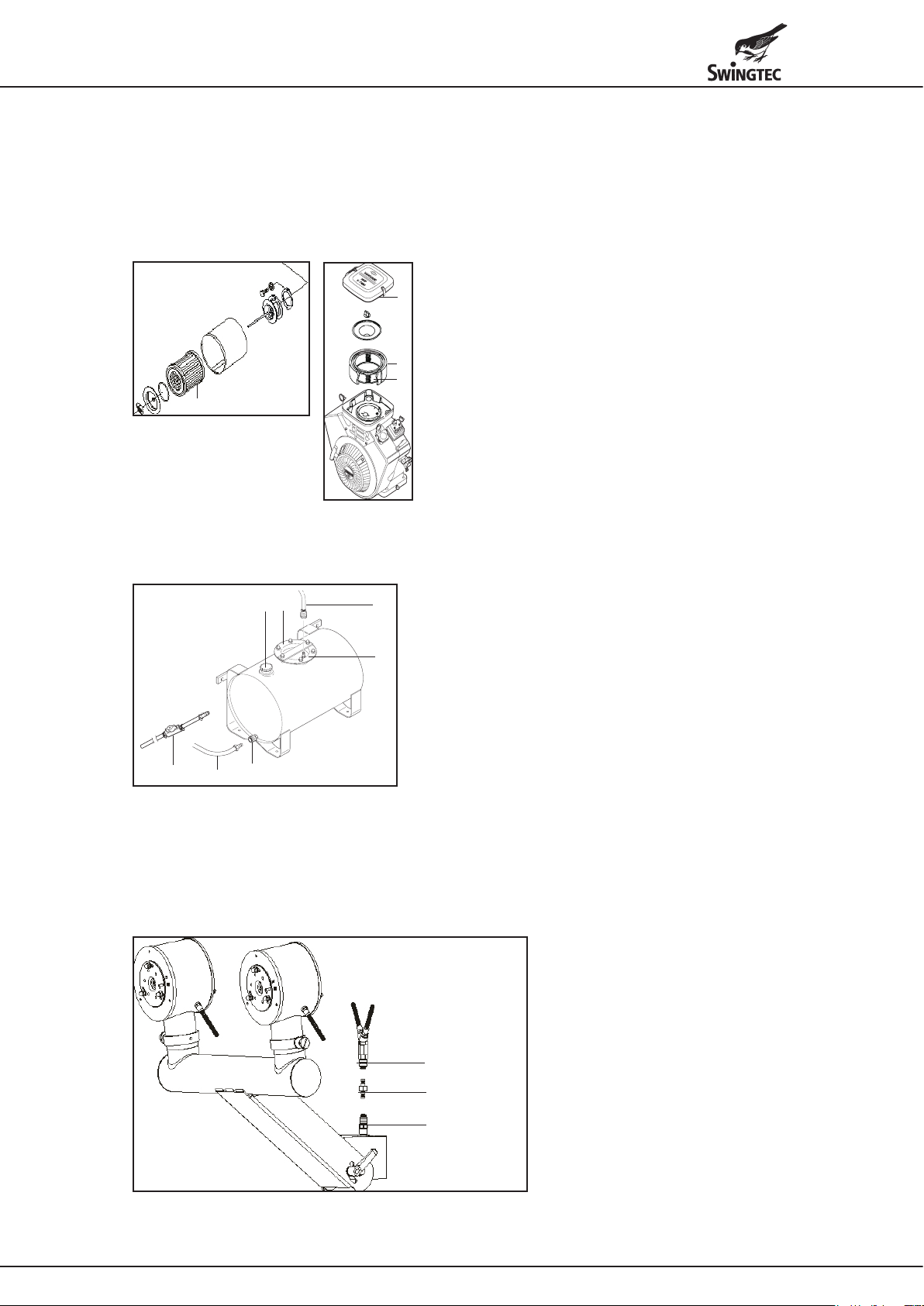
• Check the compressor's air filter (15) and the engine's air filters. This is especially important if the device is operated
in a dusty environment. Clean the filters if contaminated. Heavily contaminated filters must be replaced.
a
a Engineltercover
b Enginepre-lter
c Enginelterinsert
b
c
15
15 Airltercompressor
Fontan Mobilstar M
Device start
• Connecting the spraying tank
a
f
g
• Connect the pressure line (b) to the connection piece (c).
• Connect the solution line (d) to the quick coupling (e).
• The tank can be emptied by connecting the tank-emptying device (g) to the quick coupling (e).
The cap of the spraying tank (a) must be open to do so.
• The tank can be cleaned through the cleaning opening (f).
Selecting and assembling the dosing nozzles
To prevent manipulation of the spray output, the device is operated with fixed nozzles with defined flow rates.
e
d
b
a Capofsprayingtankwithlterinsert
b Pressure line with quick coupling
c
c Connection piece for “b”
d Solution line
e Quick coupling for “d”
f Cleaning and service opening
g Tank emptying device
a Top quick coupling solution lines
b Bottom quick coupling solution line
a
c Dosing nozzle
c
b
5

• Release the quick coupling (a) by lifting it off the dosing nozzle (c).
• Release the quick coupling (b) by pressing down the dosing nozzle.
• Remove the dosing nozzle and insert the selected nozzle.
• Fix the dosing nozzle by firmly pressing in the two quick couplings (the quick couplings must engage).
Standard dosing nozzles with nozzle designation and flow rates (measured with water):
ULV spraying process ULV-Plus spraying process LV spraying process
Nozzle number/output Nozzle number/output Nozzle number/output
1 20 l/h 4 50 l/h 7 40 l/h
2 25 l/h 5 70 l/h 8 70 l/h
3 30 l/h 6 90 l/h 9 100 l/h
10 10 l/h
11 15 l/h
12 40 l/h
Additional nozzles with specific spray outputs are available if required (optional accessory).
Control unit / remote control
The control unit is attached to the device and can be detached and used as a remote control (e.g. in the driver's cab).
f
e
c
b
d
a
g
j
i
a Ignition key
b Rotary switch: spray/stop/rinse
c Stop position
d Spraying LED
e Rinsing LED
f LV operation LED
g ULV / ULV-Plus operation LED
h
h LED signal, spraying tank empty
i Device is ready LED
j Cable for remote control
• The emergency shutdown (5) must be unlocked.
• Set the rotary switch (b) to the stop position.
• Set the ignition key (a) to the “1” position.
• Start the engine by turning the ignition key to the right or by pressing the start button (7). The ignition key must be in
the “1” position.
When starting the device, the choke (13) must be pulled. The choke can be accessed through an opening in the
hood of the device and must be pushed back immediately after the device starts.
• If necessary, the engine can also be started using the manual recoil starter (12). The ignition key must be in the
“1” position and the battery (14) must be connected (even if it is not charged).
The manual recoil starter can be accessed by opening the cover in the device's hood. When starting with the
manual recoil starter, the choke must also be pulled.
• To fog, set the rotary switch (b) to the spraying position. The device fogs.
• To rinse (after use), set the rotary switch to the rinsing position.
• The respective positions are indicated by LEDs.
Device stop
• Set the rotary switch (b) to the “Stop” position.
• Set the ignition key (a) to the “0” position.
• Remove the ignition key.
Operating hours metre
The Fontan Mobilstar M is equipped with an operating hours metre. The hours metre is mounted behind the door (10)
for the rinsing liquid tank (11) below the lamp.
The accumulated operating hours are permanently displayed.
The operating hours metre can be reset to “0” as follows:
• Press the S1 button until “05” appears on the display.
• After approx. 10 seconds, the display will show the accumulated operating hours again.
• Simultaneously press and hold the S1 and S2 buttons for approx. 20 - 30 seconds.
This deletes the accumulated operating hours.
• Release the “S1” button and wait for about 10 seconds until “0.0” appears on the display.
Once the device is restarted, the operating hours counter metre is starting again at “0.0”.
6
Fontan Mobilstar E and ER
Device start
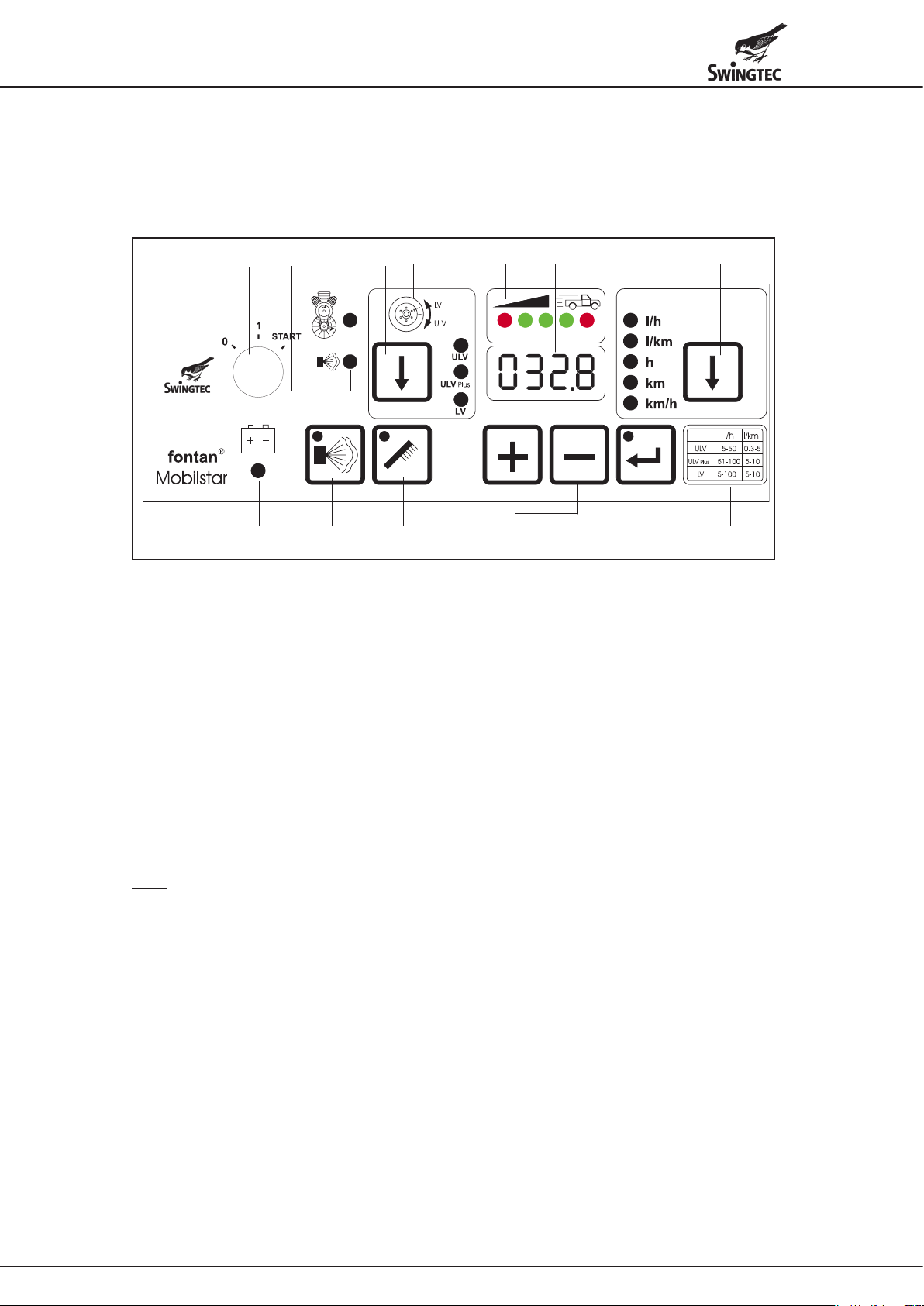
Control unit / remote control
The control unit is attached to the device and can be detached and used as a remote control (e.g. in the driver's cab).
a m b dn
l
c
e
k fhgji
a Ignition key
b ULV / ULV-Plus / LV spraying method selector button
The spraying method is indicated by LEDs.
c Note on correct setting of the spray heads
ULV / ULV-Plus or LV (see page 4 below)
d Display
e * Output method litres per hour or litres per kilometre button
The selected method is indicated by LEDs.
The operating hours (h), the distance travelled (km) and the current vehicle speed (km/h) can also be called
f Table of output capacities “litres/hour” and “litres/km” for ULV / ULV-Plus / LV spraying methods
g Input buttons for spray output (shown in display “d”)
h ConrmationbuttonfortheselectedsprayingprogramwithLED
i Spray button with LED
j Rinse button with LED
k LED display: device ready
l LED display: malfunction in fog liquid system
m LED display: malfunction in motor/compressor system
n * Display of the correct vehicle speed (green and red LEDs)
up with the button. The vehicle speed is shown in display “d”.
* Note
The displays and functions l/km and km, km/h and the correct vehicle speed “n” listed under “e” apply only to the
Mobilstar ER device.
All other indicators and functions apply to both the Fontan Mobilstar E and ER devices.
• Preparation according to the regulations on page 4.
• The Fontan Mobilstar E and ER models are not equipped with a spraying tank. The fog liquid is conveyed through
a stainless steel pump from a separate tank. We offer spraying tanks with capacities of 69 l (stainless steel), as well
as 80 l, 150 l, 300 l and 500 l (polyethylene). All tanks are equipped with a quick coupling for connecting the solution
line (16) and with a ventilation in the tank cap.
• Connect the solution line page 5 (d) to the quick coupling on page 5 (e).
• The emergency shutdown page 4 (5) must be unlocked.
• Set the ignition key (a) to the “1” position.
• Select the ULV or ULV-Plus or LV spraying methods with button (b).
• Select the output method (l/h) with button (e) (indicated by LED).
• Enter the spray output (l/h) with buttons (g) according to the values given in table (f). The selected spray output is
shown on the display (d).
• Press the confirm button (h) for the selected spraying program.
• Start the engine by turning the ignition key to the right or by pressing the start button (7). The ignition key must be in
the “1” position.
When starting the device, the choke (13) must be pulled. The choke can be accessed through an opening in the
hood of the device and must be pushed back immediately after the device starts.
7

• If necessary, the engine can also be started using the manual recoil starter (12). The ignition key must be in the “1”
position and the battery (14) must be connected (even if it is not charged).
The manual recoil starter can be accessed by opening the cover in the device's hood. When starting with the
manual recoil starter, the choke must also be pulled.
• Confirm the spraying program again with button (h).
Once the engine has been started, the spraying program can no longer be changed. Changing the program is only
possible if the engine is turned off and the spraying program is re-entered as described above.
• Start spraying by pressing button (i).
• To rinse (after use): stop spraying by pressing button (i) and start rinsing by pressing button (j).
• Call up the operating hours “h” by pressing button (e).
Indicated by LED and in the display (d).
Device stop
• Same as described on page 6 for the Fontan Mobilstar M.
Decommissioning
• As described on page 5 (above).
Special functions Fontan Mobilstar ER
The Fontan Mobilstar ER can be operated both with the “litres per hour” spraying method with a constant spray output
as well as with a variable spray output “litres per kilometre”.
The device is equipped with a GPS system
The GPS measures the vehicle speed and automatically synchronises the spray output to the speed.
When the vehicle stops, the spraying also stops and a red LED lights up on the left in field (n).
Spraying resumes as soon as the vehicle is back in motion, and the spray output is controlled variably by the GPS
pursuant to the speed driven between 3-25 km/h. Three green LEDs in field (n) indicate that the vehicle is maintaining
the proper speed range.
If the vehicle drives too fast, an acoustic warning signal sounds and a red LED lights up in field (n). The driver then has
20 seconds to reduce the vehicle speed and return the vehicle to the proper, green LED range.
If the vehicle speed is too high for more than 20 seconds, the device shuts off automatically, as proper use is not
possible if the speed is continuously too high.
The “l/km” method is used to achieve an even aerosol droplet distribution, thus avoiding over- and under-dosing of the
substance.
The variable spray output method also yields significant savings of costly substances.
Device start
• Preparation according to the regulations on page 4.
• Device operation according to the specifications for the Fontan Mobilstar E.
• Select the output method (l/km) with button (e) (indicated by LED).
• Enter the spray output (l/km) with buttons (g) according to the values given in table (f).
The selected spray output is shown on the display (d).
• Display of the correct vehicle speed via the LEDs (n), red and green.
• Call up the operating hours “h” by pressing button (e).
Indicated by LED and in the display (d).
• Call up the driven kilometres “km” by pressing button (e).
Display by LED and in the display (d).
• Call up the currently driven speed “km/h”.
Indicated by LED and in the display (d).
Tachometer function
Device stop
• Same as described on page 6 for the Fontan Mobilstar M.
Decommissioning
• As described on page 5.
Security codes Fontan Mobilstar E and ER
To exclude tampering, the following functions can be locked by entering a code:
• Spraying method ULV, ULV-Plus and LV
and
• Spray output l/h (Mobilstar E) and l/h and l/km (Mobilstar ER)
The lock can be suspended by entering a code.
8
 Loading...