

Page 1
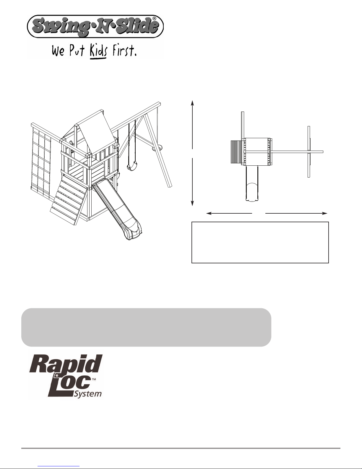
28'
26'
No. of Children: Up to 10
Min. Use Zone: 26' x 28'
Set Dim. 14'W x 14'L x 11'H
Est. Building Time: 3-6 hr.
PB 8242 - PB 8244
check out http://www.swing-n-slide.com/planupdates.htm
for updates to these instructions
For more information, visit this link:
http://www.swing-n-slide.com/
ASSEMBLY INSTRUCTIONS
Swing•N•Slide • 1212 Barberry Drive • Janesville, W
isit our web site at:
V
.swing-n-slide.com
www
or call us at
isconsin 53545
1-800-888-1232
Page 2

Safety Checklist for Swing-N-Slide Accessories
R
bserving the following statements and warnings reduces the likelihood of serious or fatal injury
O
Installation Safety – Have You:
Consulted the assembly instructions supplied with your particular model?
Noted this accessory is to be used only on Swing•N•Slide approved designs? (Do not alter its design or add/remove components.)
Made sure all hardware is tightened securely? (Supplied bolt covers must also be fastened securely.)
Using a hacksaw, cut off all protruding threaded ends of bolts and other fasteners and remove any sharp edges with
a metal file as needed?
Placed the equipment on level ground, not less than six feet (1.8 meters) from any structure or obstruction such as a fence, garage,
house, overhanging branches, laundry lines, or electrical wires?
Made sure home playground equipment is not installed over concrete, asphalt, packed earth or any other hard surface? (A fall onto
a hard surface can result in serious injury to the equipment user.)
Verified that suspended climbing ropes, chain,or cable are secured at both ends?
Consulted in assembly instructions of your particular model for minimum use zones?
Followed all anchoring and shock absorbing surfacing requirements later in this guide as they apply?
Made sure not to allow children to use equipment until it is properly installed?
Operating Safety – Have You:
Determined that on-site adult supervision is provided for children of all ages?
Warned children the following before allowing them to use the equipment?
Not to walk close to, in front of, behind or between moving items.
Not to twist swing or any other accessory chains or ropes or loop them over the top support bar since this will reduce the
strength of chain or rope.
Not to swing empty seats or other accessories.
Be sure to sit in the center of the swing seat and other accessories with full weight on the seat.
Not to attach items to the playground equipment that are not specifically designed for use with the equipment such as but not
limited to, jump ropes, clotheslines, pet leashes, cables and chain. They may cause a strangulation hazard.
Not to use equipment in a manner other than intended.
Not to get off equipment while it is in motion.
Not to climb on the equipment when it is wet.
Determined that only one child per planned occupant seat should be allowed on this set at one time.
Determined children must be dressed appropriately for play. Avoid clothing with draw strings and loose fitting clothes which
could become entangled or snagged on equipment.
Determined that suspended climbing ropes, chain, or cable cannot be looped back upon itself.
Read and understood the following warning regarding the use of two and four passenger lawn swings?
Warning: Lawn Swings are designed for use by children over two years of age. Use by children under the age of two can result
in entrapment between the seats and back areas. Never place children in a rearward facing position or with legs between the
seat and backrest because the child’s body may pass through the opening causing entrapment of the child’s head.
Safety Maintenance –
Check all nuts and bolts twice monthly during the usage season for tightness and tighten as required? (It is
ticularly important that this procedure be followed at the beginning of each season.)
par
event the deterioration of materials, r
o pr
T
use when the temperature drops below 0° F.)
Oil all metallic moving par
Check all har
necessary. It is especially important to do this at the beginning of each new season.)
Check swing seats, chains, r
, especially near the top swing hanger or at the seat connection ar
wear
sleeve or seat itself are also signs of deterioration. If any of these conditions exist, call 1-800-888-1232 to order replacement accessories.
Have You Determined to:
emove plastic swing seats and other plastic accessories and take indoors? (Do not
ts monthly during usage period?
e and equipment for sharp edges twice monthly during usage season? (Replace when
dwar
opes and cables monthly during usage season for evidence of deterioration? Severe rusting or excessive
e evidence of chain deterioration. Cracks in the pr
otective plastic
Disposal Instr
When the equipment is taken out of service, it must be disassembled and disposed of in such a way that no unreasonable hazards
will exist at the time the set is discarded.
uctions
Important!
Additional Safety Instructions for all Swing-N-Slide Playground Equipment.
Save this instr
uction sheet in the event the manufactur
er needs to be contacted.
2
Page 3
This product is intended for single family home/residential use only and not intended for use in any public setting.
According to ASTM requirements, all kits must be anchored to the ground and, if the unit has a climbing rope, the rope end must be anchored to the ground. If soil conditions
permit stakes to be pulled out easily, cementing into ground is necessary.
• To anchor the unit to the ground, use 2" x 4" x 18" (45mm x 95mm x 457mm) pressure-treated stakes. Pound stakes into ground at least 12" (305mm) at all inside corners of the
posts (including A-frame legs and climbing unit posts). Attach with four (4) 16D (3-1/2") galvanized nails per stake into each 4" x 4" (95mm x 95mm) post.
•
If the unit has a climbing rope,anchor the rope end.
• Once the unit is completely assembled and before children are allowed to play on it, proper shock-absorbing surfacing material must be installed. This may be accomplished by
using loose-fill materials at a sufficient depth. The Consumer Product Safety Commission “Handbook for Public Playground Safety” lists the following materials and required
depths that are sufficient for home/residential application. For fall height protection up to 9 ft. (2.742m) [recommended for Swing•N•Slide kits]:
Double Shredded Bark Mulch 9" (229mm)
These depths were derived from the CPSC Handbook. Swing•N•Slide has not done independent tests to determine these required depths.
When properly installed, shock absorbing material will completely cover the horizontal baseboards on climbing units. This protective surfacing must extend a minimum of 6 ft.
(1.828m) in all directions from the perimeter of the equipment or from the outermost edges of any component. For example, a slide extending beyond the platform must have
protective surfacing at least 6 ft. (1.828mm) out from both sides as well as the end. For swings, the protective surface must extend
front of the swing when the swing is in its rest position.
Placement in any public setting constitutes a misuse of this product.
MPORTANT
ADDITIONAL REQUIRED SAFETY INSTALLATION INSTRUCTIONS
LOOSE FILL MATERIAL REQUIRED (UNCOMPRESSED) DEPTH1in. (mm)
Wood Mulch 9" (229mm)
Uniform Wood Chips 12" (305mm)
Fine Sand 12" (305mm)
Fine Gravel 12" (305mm)
I
!
at least 14 ft. (6m) out from both the back and
Este producto ha sido ideado para su uso en una residencia u hogar de una sola familia y no para usarse en zonas públicas.
Según establece el ASTM, todos los equipos deben anclarse al terreno y si la unidad tiene además una cuerda de escalar, el final de la cuerda deberá anclarse al suelo. Si las
condiciones del terreno permiten que las estacas se salgan con facilidad, será entonces necesario cementarlas a la tierra.
• Para anclar la unidad a la tierra, use estacas tratadas bajo presión de 2 x 4 x 18 pulgadas (45 mm x 95 mm x 457 mm). Martillee las estacas en la tierra a una profundidad de al
menos 12 pulgadas (305 mm) en todas las esquinas internas de los postes (incluyendo las patas de la estructura A y los postes de la unidad de escalada). Sujételos con cuatro (4)
clavos galvanizados de 16D (3-1/2 pulgadas) por estaca en cada poste de 4 x 4 pulgadas (95 mm x 95 mm).
• Si la unidad tiene una cuerda de escalar, sujete el final de la cuerda.
• Una vez que la unidad esté completamente montada y antes de que se permita a los niños jugar en ella, deberá instalarse el material adecuado para la absorción de golpes. Esto
se consigue usando materiales de relleno a una profundidad suficiente. En el folleto titulado “Guía para la Seguridad en las zonas de recreo publicas” publicada por la Comisión
de Seguridad para los Productos de Consumo (CPSC por sus siglas en inglés) se citan los siguientes materiales y los requisitos necesarios para su uso en residencias y hogares
privados. Para protegerse de caídas de hasta 9 pies de altura (2,742 m), recomendado para los equipos Swing•N•Slide:
stas medidas se han sacado de la Publicación de la CPSC. Swing•N•Slide no ha realizado estudios independientes para determinar estos espesores recomendados.
E
Una vez instalado adecuadamente el material de absorción de golpes, este deberá cubrir completamente todas las bases horizontales de las unidades de escalada. Esta superficie
protectora deberá extenderse por al menos 6 pies (1,828 m) en todas las direcciones, desde el perímetro del equipo o desde los bordes externos de cualquiera de los componentes.
Por ejemplo, un tobogán que se extiende por fuera de la platafor
Para los columpios, la superficie protegida deberá extenderse al menos 14 pies (6 m) a partir de tanto la parte trasera como delantera del columpio cuando este esté en posición
inmóvil.
Ce pr
oduit est conçu uniquement pour un usage résidentiel. Il ne saurait aucunement convenir aux installations publiques.
Les normes établies par l’organisme américain ASTM spécifient que toutes les unités de jeu doivent être ancrées solidement dans le sol et que si l’unité comprend une corde
d’escalade, l’extrémité de celle-ci doit également être ancrée dans le sol. Si les piquets risquent d’être facilement délogés en raison du type de sol, il est nécessaire de les cimenter
dans le sol.
Pour ancrer l’unité dans le sol, utiliser des piquets en bois traités sous pression de 2 x 4 x 18 po
•
(45 x 95 x 457 mm). Enfoncer les piquets dans le sol à une pr
A et les poteaux des unités d’escalade). Fixer les piquets au moyen de quatre clous galvanisés 16D de 3-1/2 po (par piquet) dans chaque montant de 4 x 4 po (95 x 95 mm).
• Si l’unité comprend une corde d’escalade, ancrer l’extrémité de la corde dans le sol.
• Lorsque l’unité est entièrement assemblée, un matériau de protection amortisseur doit être installé sur le sol avant de permettre aux enfants de s’amuser. Des matériaux
particulaires d’une épaisseur suffisante peuvent être utilisés à cette fin. Le guide américain intitulé «Handbook for Public Playground Safety» rédigé par la Consumer Product
Safety Commission (CPSC) des États-Unis r
9 pieds (2,742 m) [r
ecommandation pour les unités Swing•N•Slide]:
Su uso en lugares públicos constituye una mala utilización de este producto.
INSTRUCCIONES ADICIONALES DE SEGURIDAD PARA LA INSTALACION
ERIALES DE RELLENO
MAT
Mezcla de madera 9 pulgadas (229 mm)
Mezcla de corteza de doble trituración 9 pulgadas (229 mm)
Viruta de madera uniforme 12 pulgadas (305 mm)
Arena Fina 12 pulgadas (305 mm)
Grava fina 12 pulgadas (305 mm)
’utilisation dans un endr
L
ofondeur d’au moins 12 po (305 mm) à tous les coins intérieurs des montants (y compris les montants des str
ecommande une liste de matériaux et spécifie l’épaisseur requise pour un usage résidentiel. Protection contre les chutes d’une hauteur de
¡IMPORTANTE!
SIN COMPRIMIR) DE 1 PULGADA ( 25,4 MM)DE PROFUNDIDAD
(
ma, deberá tener una superficie protegida de al menos 6 pies (1,828 m) a ambos lados así como en el extremo final.
oit public constitue un usage abusif du pr
IMPORTANT!
CONSIGNES DE SÉCURITÉ SUPPLÉMENT
AIRES
oduit.
uctur
es en
MATÉRIAUX PARTICULAIRES ÉPAISSEUR1 RECOMMANDÉE (NON COMPRIMÉE) IN. (MM)
Paillis de bois 9 po (229 mm)
Paillis d’écor
Copeaux de bois unifor
Ces valeurs sont tirées du guide de la CPSC. Les unités Swing•N•Slide n’ont pas fait l’objet d’essais indépendants afin de déter
Pour que l’installation soit adéquate, le matériau amor
l’installation sur un minimum de 6 pi (1,828 m) à partir du pourtour de l’unité ou des composants les plus éloignés. Par exemple, une glissoire qui se prolonge au-delà de la plateforme doit être entourée d’une surface de protection d’au moins 6 pi de chaque côté ainsi qu’à l’extrémité. En ce qui concerne les balançoires, la zone de protection doit couvrir au
moins 14 pi (6 m) autant devant que der
ce filamentée 9 po (229 mm)
Sable fin 12 po (305 mm)
Gravier fin
tisseur doit r
e la balançoire lorsque celle-ci est immobile.
rièr
mes
ecouvrir entiér
12 po (305 mm)
12 po (305 mm)
miner l’épaisseur r
ement la base horizontale des unités d’escalade. La surface de protection doit entourer
ecommandée des matériaux.
3
Page 4

PB 8242 -PB 8244
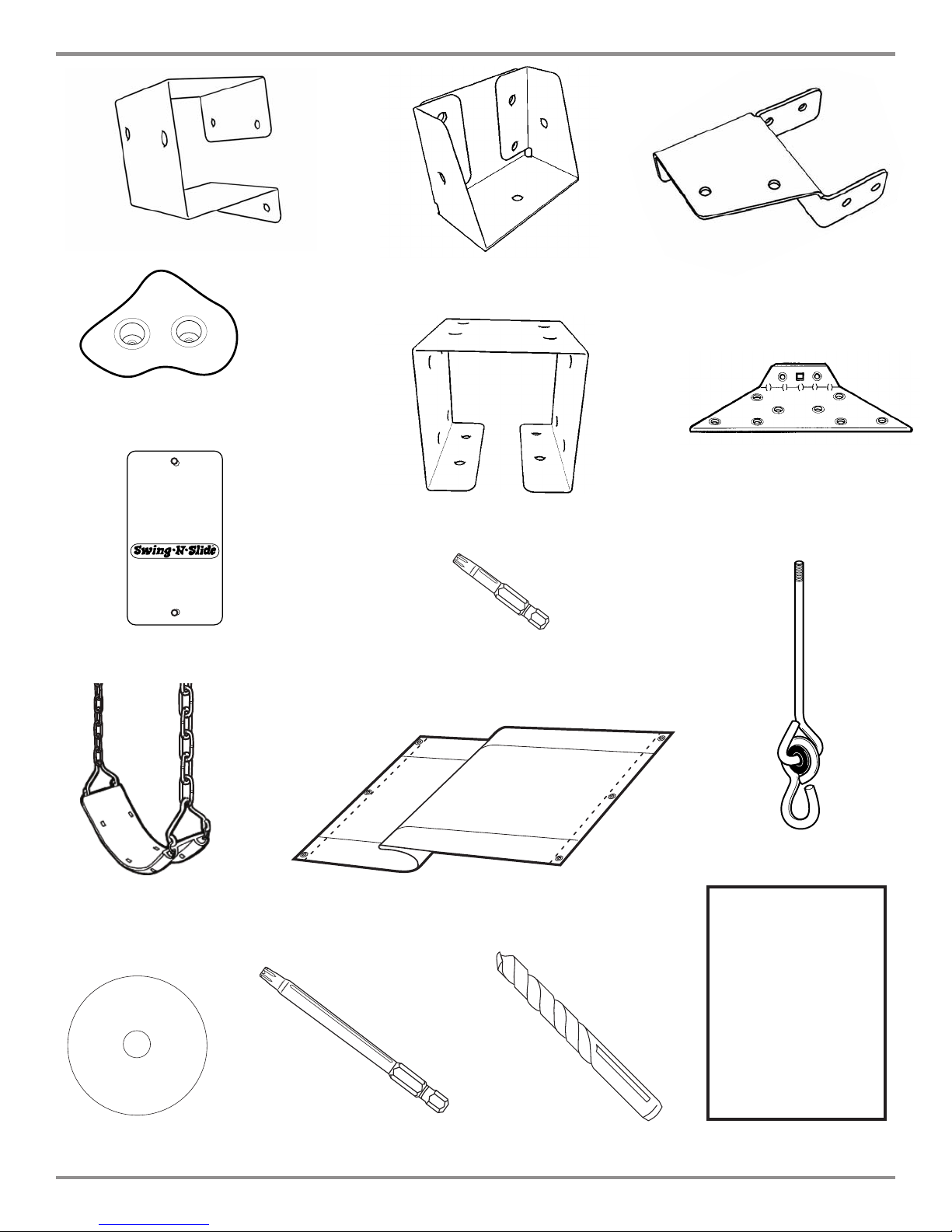
KIT CONTENTS
TOOLS REQUIRED
ELECTRIC DRILL
TAPE MEASURE
(2) 1-3/4'' panhead screws
(2) 1/2'' panhead screws
1/2" SOCKET & WRENCH
SAFETY GLASSES
& DUST MASK
PHILLIPS BIT
(6) T- nuts
HAMMER
CARPENTER'S SQUARE
(2) 5/16'' flat washers
(105) 2" lag screw
(34) 1-1/4'' screws
(44) 1-1/2'' screws
(224) 2-1/2'' screws
(2) 3-1/2'' Bolts
(2) 1/4'' flat washers
(7) 1'' Truss Screw
4
4
(6) Tarp Washers
(4) Bottom Beam Clamps
(slotted)
Page 5
PB 8242-PB 8244
THIS PRODUCT IS
I
NTENDED FOR USE
BY CHILDREN FROM
A
GES 2-10 YEARS
For Home / Residential
Use ONLY
1212 Barberry Drive
Janesville, WI 53545
1-800-888-1232
www.swing-n-slide.com
BLACK
R
(4) Shelf-Loc
(8) Climbing Rocks
With Hardware
(1) Name Plate
(2) Split Beam bracket
(8) Cup-Loc
(2) EZ Frame Brackets
(8) Wrap-Loc
(1) T20 Torx® Bit
(2) Swing Seat
weight limit: 115 lbs.
(1) Instructional DVD
(1) T30
orx® Bit
T
(1) Canopy
5
5
3/8" DRILL
BIT (5'' Min.)
(4) Swing Hangers
PB 8242
PB 8244
Plan
(1) Plan
Page 6
PB 8242 -PB 8244
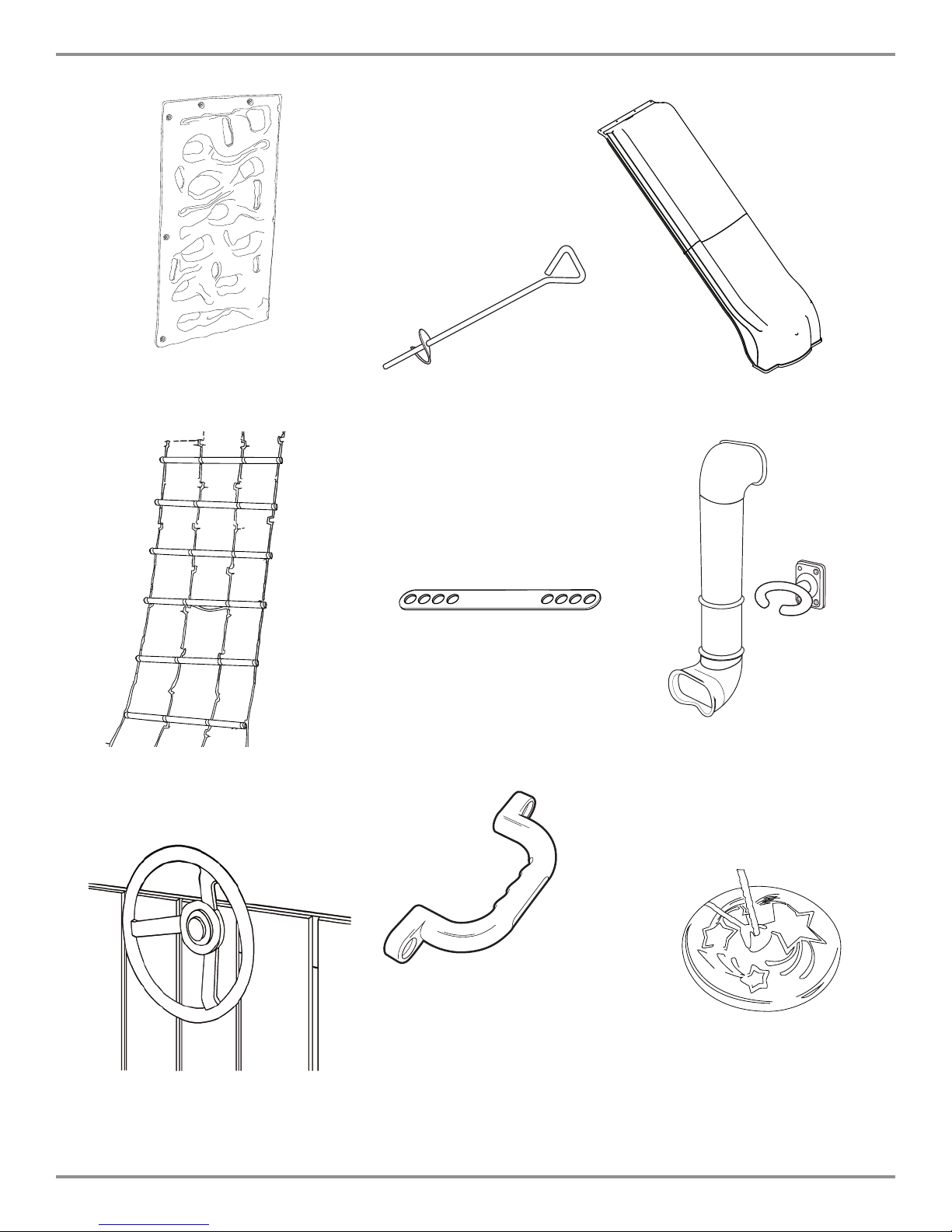
(1) Cliff Climber
(1) Pirate's Ladder
with hardware
(4) Anchor-It
With Hardware
(4) Anchor-It Straps
(1) Summit Slide
with hardware
(1) Periscope
With Hardware
(1) Steering Wheel
With Hardware
(1) Safety Handle
6
6
(1) Disc Swing
ith Hardware
W
Page 7

(1) 2'' x 4'' x 40-1/2''
(3) 2'' x 4'' x 47-1/2''
(2) 5/4'' x 4'' x 20-3/4''
(1) 5/4'' x 4'' x 17''
(1) 5/4'' x 4'' x 46-1/2''
(14) 5/4'' x 4'' x 47-1/2''
(6) 5/4'' x 6'' x 30''
(9) 5/4'' x 6'' x 40-1/2''
(11) 5/4'' x 6'' x 47-1/2''
(4) 4'' x 4'' x 39-3/4''
(1) 4'' x 4'' x 47-1/2''
(2) 5/4'' x 4'' x 34''
PLASTIC COATED LUMBER
(9) 4'' x 4'' x 96''
NOTE: (1) Swing Beam and (1) Accessory Board have pre-drilled holes.
PB 8242-PB 8244
Board List
7
7
Page 8

PB 8242 -PB 8244
How to select the correct fastener
Use these 3 pictorial guides to help select the correct fastener(s) for the
lumber attachment you are making. Each diagram will highlight the correct
number of fasteners to use, and where to attach them.
5/4'' Boards to 4'' x 4''
(3) 2-1/2'' screws
Apply 2 1/2" screws to the 2"x4" boards
when attaching to 4"x4" uprights.
5/4'' Boards to 5/4'' Boards
(2) 1-1/2'' screws
Use 1-3/4" screws when mounting 5/4"
boards to 5/4"x4" boards.
8
8
Page 9
PB 8242-PB 8244
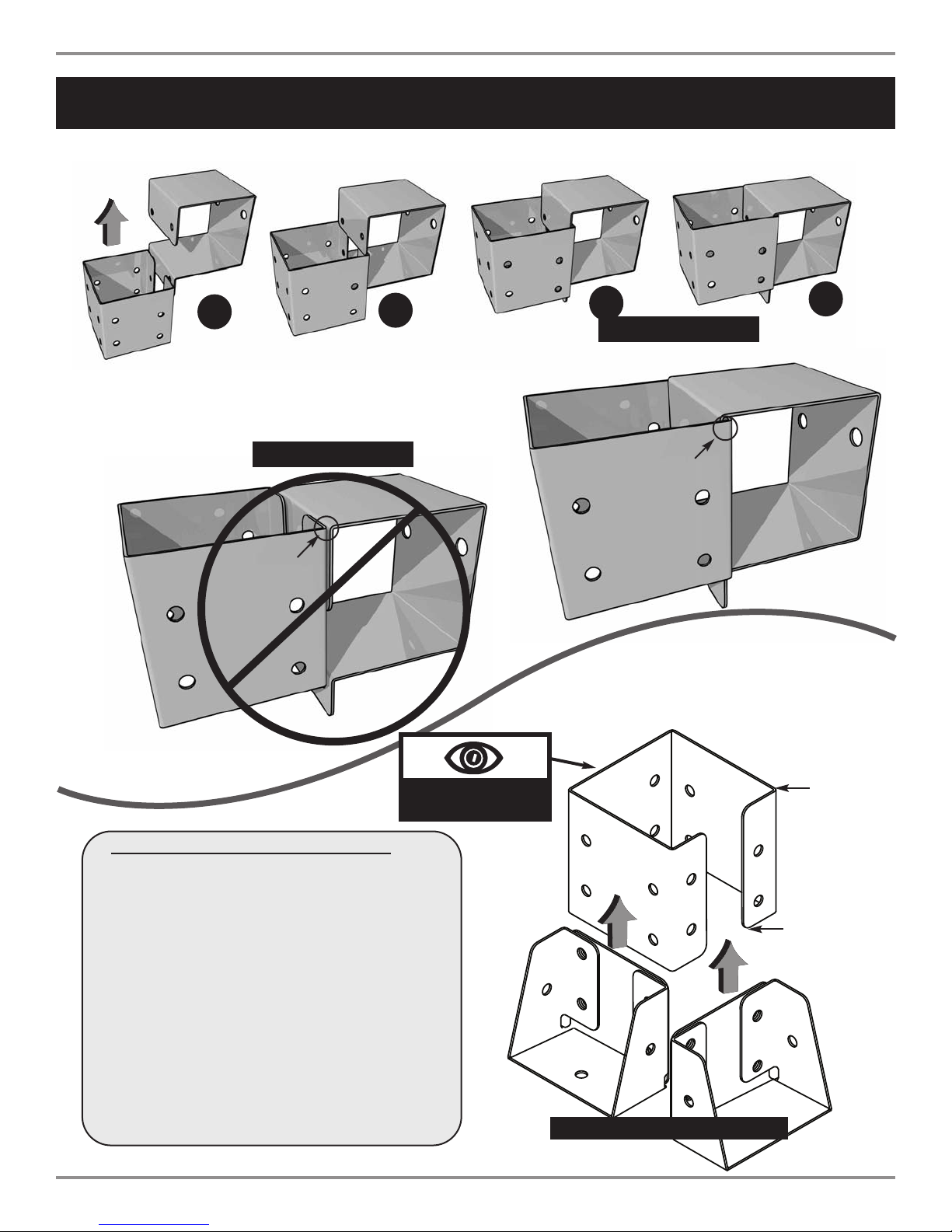
Understanding how the Bracket System Works
Shelf-Loc Bracket
Wrap-Loc
1
Example of a Shelf-Loc bracket connection.
2
3
WRONG!
rackets NOT
b
interlocked!
CORRECT!
Brackets
''clipped''
4
Look for ''TOP'' stamp on
bracket for cor
Introduction to the Bracket system
YS
A
W
AL
1.
2. Brackets ''clip'' to each other. NEVER position in
a non-interlocking position.
Use 2'' lag scr
ews on all brackets.
Example of a Cup-Loc bracket connection.
rect orientation.
Wrap-Loc
Cup-Loc
TOP
GAP
Top of bracket
Bottom of bracket
(Hole locations close to bottom)
Brackets Clip Together
9
9
Page 10

PB 8242 -PB 8244
A
BEND
WRAP
BRACKETS
TO FIT
AROUND
4'' x 4''s
AS
SHOWN
IN
A&B
B
Repeat 4x
Fig. 2
(4)
2'' lag screws
Per Bracket
43-1/4''
4'' x 4'' x 96''
REMEMBER: Brackets are inter-locking. Cup-loc will clip
and secure into the Wrap-Loc as shown below.
Fig. 1
2'' Lag screw
x 8 (4 each bracket)
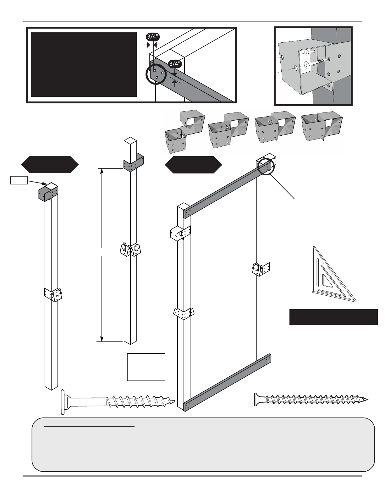
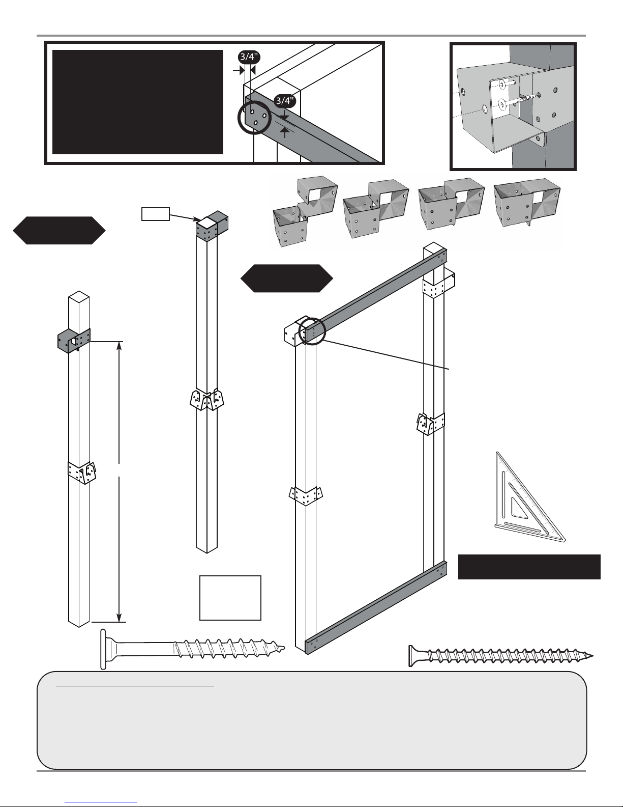
A. Frame Construction
1. Measure and position brackets on (4) 4'' x 4'' x 96’’ as shown in (Fig.1),
Fig (2).
10
10
Page 11
•WARNING•
Avoid splitting your
lumber by offsetting
your screws at least
3/4’’ from edge.
Frame 1 Construction
(2)
2'' lag screws
Per Bracket
PB 8242-PB 8244
GAP
Fig. 3
82-1/2''
Fig. 4
5/4'' x 4'' x 47-1/2
''
Screws must be
vertically aligned to pass
through the gap in the
Wrap Loc Brackets.
Double check to make
sure structure is square
Frame 1
2'' Lag screw
A. Frame Construction cont.
1. Using two (2) 4'' x 4'' x 96'' fr
2. Attach upper and lower 5/4'' boar
FLIP
FRAME
OVER
om
(Fig. 2), measur
ds as shown in
(3)
Frame 1
5/4'' x 4'' x 47-1/2''
2-1/2''
screws
per joint
2-1/2'' screw
e and position brackets on 4'' x 4'' x 96’’ as shown in
(Fig. 4)
11
11
(Fig. 3).
Page 12
PB 8242 -PB 8244
•WARNING•
Avoid splitting your
lumber by offsetting
your screws at least
3/4’’ from edge.
Frame 2 Construction
GAP
Fig. 5
(2)
2'' lag screws
Per Bracket
Fig. 6
82-1/2''
Frame 2
FLIP
FRAME
OVER
(3)
2
-1/2''
screws
per joint
5/4'' x 4'' x 47-1/2''
Frame 2
5/4'' x 4'' x 47-1/2''
Screws must be vertically
aligned to pass through the
gap in the Wrap Loc Brackets.
Double check to make
sure structure is square
2'' Lag screw
A. Frame 2 Construction cont.
1. Using two (2) 4'' x 4'' x 96'' from (Fig. 2), measure and position brackets on 4'' x 4'' x 96’’ as shown in (Fig.5).
2. Attach upper and lower 5/4'' boards as shown in (Fig. 6)
12
12
2-1/2'' screw
Page 13

PB 8242-PB 8244
Fig. 7
5/4'' x 4''
x 47-1/2''
(3)
2-1/2''
screws
per joint
Fig. 8
5/4'' x 4'' x 47-1/2''
Frame 1
5/4'' x 4'' x 47-1/2''
2-1/2'' screw
A. Frame Construction cont.
1. Install 5/4'' boar
2. Install Frame 2 as shown in (Fig. 8).
ds as in
(Fig. 7).
Frame 1
Double check to make
sure structure is square
(3)
2-1/2''
screws
per joint
Frame 2
13
13
Page 14

PB 8242 -PB 8244
Fig. 9
(4) 4'' x 4'' x 39-3/4''
Fig. 9a
2'' Lag screw
x 3
A. Frame Construction (cont.)
1. Install 4'' x 4'' beams as shown in (Fig. 9).
2. Install lag screws at each corner location as
shown in (Fig. 9a)
14
14
Page 15

Fig. 10
PB 8242-PB 8244
Fig. 10a
5/4'' x 6'' x 40-1/2''
(2)
2-1/2''
s
crews
per joint
5/4'' x 6'' x 40-1/2''
2'' x
4'' x 40-1/2''
19-1/2''
(
2)
2-1/2''
screws
per joint
2-1/2'' screw
B. Install Deck Boards
1. Install (2) 5/4'' x 6'' x 40-1/2'' deck boards as shown in (Fig. 10).
2. Attach 2'' x 4'' x 40-1/2'' to deck boards using 2-1/2'' screws as shown in (Fig. 10a).
15
15
Page 16

PB 8242 -PB 8244
(6) 5/4'' x 6'' x 47-1/2''
(2)
2-1/2''
s
crews
per joint
Fig. 11
B. Install Deck Boar
ds
1. Install (6) additional 5/4'' x 6'' x 47-1/2'' deck boards to structure as shown (Fig. 11).
2. Use two 2-1/2'' scr
ews at center and each end of deck boards.
Note: Screws at center will attach to center support.
2-1/2'' screw
16
16
Page 17

Fig. 12
PB 8242-PB 8244
C. Install Upper Rail Boards
5
''
x 47-1/2
'
5/4'' x 4'
0''
3
5/4'' x 4'' x 47-1/2''
(3)
2
-1/2''
screws
per joint
/4'' x 4'' x 47-1/2''
5/4'' x 4'' x 47-1/2''
1. Install 5/4'' boards as shown in (Fig 12).
Fig. 13
2-1/2'' screw
D. Install Lower Rail Boards
1. Install lower rail support as shown in (Fig 13).
17
17
(5)
2-1/2''
screws
5/4'' x 4'' x 20-3/4''
5/4'' x 4'' x 47-1/2''
5/4'' x 4'' x 47-1/2''
5/4'' x 4'' x 20-3/4''
(6)
2-1/2''
screws
per board
(5)
2-1/2''
screws
Page 18

PB 8242 -PB 8244
Tip: Flex brackets to make installation of
4'' x 4'' easier
Fig. 15
Approx. 1/4''
Fig. 16
Fig. 14
4'' x 4'' x 47-1/2''
2'' Lag screw
x 4
F. Install Accessory 4x4
1. Work 4'' x 4'' into brackets as shown in (Fig. 14)
and (Fig. 15).
2. Secure brackets (Fig. 16).
18
18
Page 19

H. Swing Beam Drill Locations
3-1/2''
10-1/2''
10-1/2''
24-1/2''
33-1/2''
47-1/2''
58''
63-1/2''
93-1/2''
14''
9''
14''
10-1/2''
5-1/2''
30''
96''
DISC SWING
MOUNTS HERE
1. Identify your Swing Beam by finding the
predrilled holes as pictured in (Fig. 17)
Tap T-nut into swing beam at locations shown.
2.
PB 8242-PB 8244
Fig. 17
19
19
Page 20

PB 8242 -PB 8244
(4) 1-1/4'' screws
Swing Hanger
Use Screwdriver to aid in tightening
Bottom Beam Clamp
t-nut
Hammer
3/8'' hole
Fig. 18
T-nut
I. Swing Hanger Assembly
ap t-nut into 3/8’
1. T
2. Place a bottom beam clamp over the swing hanger as shown in (Fig. 18)
3. Insert the swing hanger into the beam and thread it into the T-nut until it is flush or near flush with the top of the
-nut. A screwdriver may be used to twist the hanger
T
4. Use (4) 1-1/4'' screws to secure beam clamp.
5. Check hanger to ensure it does not spin.
6. Repeat for all swing hangers.
’ hole as shown in
(Fig. 18)
(Fig. 18). Orient swing hanger as shown in (Fig 18).
20
20
Page 21

Fig. XX
Fig. 19
Align the edges of the 4" x 4" legs
with the edges of EZ Frame Bracket
(8) 2-1/2’’ Screws
PB 8242-PB 8244
. A-Frame Assembly
J
ayout 4'' x 4’’s and 2'' x 4’’ as
1. L
shown in
2. Allign EZ Frame Bracket with face of
4’’ x 4’’s.
3. Secure EZ Frame Bracket with (8)
2-1/2’’ screws to 4'' x 4''s making
sure they are flush with each other.
4. Secure 2’’ x 4’’ to 4’’ x 4’’s as
shown in
Flip over and add 2nd bracket.
5.
Repeat steps 2 through 4.
(Fig. 19) and (Fig. 20).
(Fig. 20)
4" x 4" x 96'''
(4)
2-1/2'' screws
47"
2" x 4" x 47-1/2"
EZ Frame Bracket
Fig. 20
4" x 4" x 96''
(4)
2-1/2'' screws
94-1/2"
2-1/2'' screw
21
21
Page 22

PB 8242 -PB 8244
Can
til
eve
r beam
Fig. 21
T-nut
Washer
2-1/2'' screws
Hex Bolt
2-1/2'' screw
K. A-Frame Assembly cont.
1. Attach A-Frame beam to Swing Beam using (2) hex bolts and 4 screws.
2. Tighten hex bolt to flush with top of T-nut. Repeat on other bracket.
22
22
Page 23

PB 8242-PB 8244
L. Swing Beam Assembly.
1. Position Split-Brackets on 4'' x 4'' x 47-1/2''
Fig 22).
(
ith the help of others, lift A-Frame and
2.W
wing Beam Assembly and center onto unit as
S
shown in
3. Secure as shown in (Fig 23).
(Fig. 22)
Fig. 23
22''
Fig. 22
Swing Beam
View from Deck
Swing Beam
2'' Lag screw
x 8 (each bracket)
23
23
Page 24

PB 8242 -PB 8244
Fig. 24
Use 2-1/2'' screws to
secure to 5/4'' x 4'' to 4'' x 4''
(2)
1-1/2'' deck screws
per joint
(5) 5/4'' x 6'' x 47-1/2''
N. Barrier Boar
1. Install 5/4'' bar
the opening.
ds
rier boar
ds evenly spaced in
24
24
1-1/2'' screw
2-1/2'' screw
Page 25

Fig. 25
PB 8242-PB 8244
(2) 5/4'' x 6'' x 30''
(2) 5/4'' x 6'' x 30''
O. Barrier Boards cont.
(2)
1-1/2'' deck screws
p
er joint
1-1/2'' screw
2. Install 5/4'' x 30'' barrier boar
spaced in the opening. See (Fig. 25).
25
25
ds evenly
Page 26

PB 8242 -PB 8244
Fig. 26
1-1/2''
5/4'' x 6'' x 30''
5/4'' x 6'' x 30''
(
2)
1-1/2'' deck screws
per joint
1-1/2''
O. Barrier Boards cont.
3. Install 5/4'' x 30'' bar
shown in
(Fig. 26).
rier spaced to cr
eate an opening as
1-1/2'' screw
26
26
Page 27

Fig. 27
3-1/2''
60''
96''
70''
80''
90''
60''
10''
10''
10''
PB 8242-PB 8244
H. Accessory Beam Drill Locations
1. Identify your Accessory Beam by the predrilled
holes as pictured in (Fig. 27)
27
27
Page 28

PB 8242 -PB 8244
Tip: Flex brackets to make installation of
4'' x 4'' easier
Fig. 28a
Approx. 1/4''
Fig. 28
4'' x 4'' x 96''
Fig. 28b
4'' x 4'' x 96''
2'' lag screws
F. Install Accessory 4x4
ork 4'' x 4'' into brackets as shown in
1. W
(Fig. 28a).
2. Secur
e brackets
(Fig. 28b).
Note: Drill Holes in 4'' x 4''
before mounting
(4)
(Fig. 28),
2'' Lag screw
x 4
3. Attach accessory 4'' x 4'' to base board as shown
in (Fig. 28).
28
28
Page 29

Fig. 29
1. Connect 5/4'' x 4'' x 34''
to center 5/4'' x 6'' fence panel.
(2)
2-1/2'' screws
p
er joint
PB 8242-PB 8244
(3)
2-1/2'' screws
5/4'' x 4'' x 46-1/2''
5/4'' x 4'' x 34''
5/4'' x 4'' x 34''
2. Align 5/4'' x 4'' x 34''
with opposite 5/4'' x 4'' x 34''
2-1/2'' screw
S. Roof Support.
1. Install 5/4'' x 4'' boar
29
29
ds as shown in
(Fig. 29).
Page 30

PB 8242 -PB 8244
Fig. 30
T. Install Tarp.
1. Install canopy as shown in (Fig. 30)
2. Secure canopy in six locations (Fig. 30a).
30
30
Fig. 30a
1-1/4'' screw
Page 31

Fig. 31
PB 8242-PB 8244
U. Install Protective Barrier Board
1. Secure protective 5/4'' barrier board as shown in (Fig 31).
5/4'' x 4'' x 47-1/2''
30''
2-1/2'' screw
(3)
2-1/2'' screws
31
31
Page 32

PB 8242 -PB 8244
Fig. 32
(7) 5/4'' x 6'' x 40-1/2''
(2)
2
-1/2'' screws
p
er joint
Rock Wall Assembly.
(2) 2'' x 4'' x 47-1/2''
2-1/2'' screw
Fig. 32a
(3)
2-1/2'' screws
per joint
1. Assemble Rock Wall as shown in (Fig. 32). Make sure to space the 5/4'' x 6'' boards as evenly as possible.
2. Mount Rocks to wall in a pattern that will allow your child to access the deck easily. Mount rocks per attached
instructions.
3. Attach the Rock Wall to the unit as shown in (Fig. 32a).
Climbing Rock Installation
Mark locations of Climbing Rocks on the
1.
Fig. 32b
(2)"T" nuts
Climbing Wall in a pattern that will easily
allow your child to climb to the deck
. Make
sure the bolt hole locations are clear of wall
supports before drilling.
2.Drill holes through the wall at the desired
locations using a 3/8" drill bit. Install Climbing
Rocks as shown in (Fig. 32b).
3/8" Holes
3. Make sure the Climbing Wall and Climbing
Rock connections are secure before allowing
any children to play on the Climbing Wall.
(2) 1-1/2'' Hex Head Bolts
Hold (rock)
(1) Loc W
(1) Flat Washer per bolt
asher per bolt
WARNING:
Verify Rock Hardware BEFORE Drilling Holes
32
32
Page 33

PB 8242-PB 8244
Fig. 33
W. Slide Installation.
1. Assemble two piece slide by bolting
together at 11 locations using
(1) 5/16'' x 3/4'' head bolt,
(1) 5-16'' loc-nut and
(2) 5/16'' flat washers at each location.
See (Fig. 33).
2. Position slide to determine proper location
for stake.
3. Drive wood stake into ground leaving 2''
exposed.
4. Secure the slide bottom to the stake using
(2) 1-1/4'' deck screws. (Fig. 33a).
5. Attach slide to unit as shown in
(Fig. 33b).
Fig. 33a
Fig. 33b
(
2)
1-1/4'' screws
per joint
5/4'' x 4'' x 17''
2'' Above Ground
33
33
(4)
1'' Truss Screw
Use truss head screws
to secure slide to deck.
Page 34

PB 8242 -PB 8244
Fig. 33c
(5)
2'' Lag screw
W. Cliff Climber Installation.
1. Attach Cliff Climber to tower at the 5
locations where holes are drilled through
the Cliff Climber on the side & top.
2. Attach Cliff Climber to the bottom rail
through 3 holes in the bottom lip as
shown in
(Fig. 33c).
(3)
1'' Truss Screw
Use truss head screws
to secure climber to unit.
34
34
Page 35

PB 8242-PB 8244
Fig. 34
Fig. 35
NEVER
hang a swing seat by a
partial link of chain! Remove and
discard partial links.
X. Swing Seat Assembly.
. Hold the swing seat vertically and insert uncoated chains through
1
he channels on the bottom of the swing seat. Note:A coat
t
anger may be used to help pull chain through the swing seat.
h
One full link should show at each end of the seat
2. Place one covered chain onto each harness so that it fits at the top
of the V-hanger. Insert uncoated chains to bottom vinyl hooks of
V-hanger.(Fig. 36). Crimp harness end closed.
CAUTION: It is important that you crimp harness
ends completely closed before using (see Fig. 36).
Place end of harness with hooks on a hard surface and force
hooks closed with a hammer or squeeze closed with a pliers
until parts are touching.
cause deep cuts.
3. Hang the chains from the nylon bushing swing hangers. Crimp the
hook opening closed with a pliers to secure the chains to the
swing hangers
crimped and secure before using swing seat.
(Fig. 37). Make sure all connections are tightly
WARNING: Open hooks can
(Fig. 34).
Fig. 36
Fig. 37
35
35
Page 36

PB 8242 -PB 8244
Fig. 38
Anchor-It
Flat Washer
metal strap
1-1/2"
lag bolt
Anchor-It
Y. Anchor-It Installation.
Instructions for Anchoring Swing•N•Slide Activity Centers
1. Determine the final location of your activity center.
2. Place the Anchor-It stakes adjacent to the base and near the corners of your activity center (at the bottom of the
legs on swing sets) and twist the auger-style stakes into the ground until only the loop is exposed.
3. Place the metal strap through the loop of the Anchor-It stake and secure it to the unit with a lag screw and
washer as illustrated to the right. Note: Attach the strap to the unit with as little play as possible using whatever
holes in the strap that work best.
36
36
Page 37

Pirate’s Ladder
Pirate’s Ladder
Pirates Ladder.
1. Bolt Pirates Ladder to top 4'' x 4'' support at 4 locations
as shown using (4) 3/8'' loc nuts and (4) 3/8'' flat
washers (Fig. 39).
Note: Refer to (Fig. 27) for accessory arm placement.
Fig. 39a
PB 8242-PB 8244
Fig. 39
3. Using two r
Pirate's Ladder rope. Tap two staples in place
appr
4'' x 4''. Then thr
Double the rope back on itself and through the first
staple. Pull the rope tight and secure in place by
pounding staples in place. See
ope staples to secur
oximately 1'' apar
ead the r
t. Wrap the rope under the
e the bottom of each
ope thr
ough both staples.
(Fig. 39b).
2. Attach bolt covers over loc nuts at all four locations
using (2) 1-1/4'' deck screws each, as shown in
(Fig. 39a).
Fig. 39b
4'' x 4'' x 96''
1''
4. Secure end of each rope to 4'' x 4'' using supplied
rope staples.
3737
37
1''
Page 38

PB 8242 -PB 8244
Disc Swing / Safety Handle
Disc Swing / Safety Handle
INSTRUCTIONS
Attach the rope to the swing beam by slipping the eye bolt
through the hole and secure it with a 3/8" flat washer and loc
nut. Place a bolt cover over the exposed bolt end and secure it
using two 1-1/4” screws as shown in
(Fig. 1).
Fig. 1
1-1/4” screws
Bolt Cover
Loc Nut
Washer
swing beam
Fig. 2
washer
1 - 3/4
Panhead
screw
11"
Deck Surface
V. Safety Handles.
1. Mount safety handle in the Cliff Climber opening
appr
2. Refer
38
38
oximately 11'' above the deck sur
ence
(Fig. 33c) for Clif
f Climber assembly
face
(Fig. 2).
.
Page 39

NSTRUCTIONS:
I
1. Choose a desired location for the steering wheel
and drill a 3/8" diameter hole through the lumber.
NOTE: If lumber is greater than 2" in depth, you
will need to counterbore the hole appropriately.
2. Mount steering wheel to climbing unit as indicated
in (Fig. 1).
3. Snap steering wheel cap into place
(Fig. 1).
Fig. 1
PB 8242-PB 8244
Steering Wheel
Steering Wheel
Carriage Bolt
flat washer
loc nut
steering wheel cap
spacer
Periscope
Periscope
Installation Instructions:
1. Position mounting bracket in desired location as indicated.
2. Attach mounting bracket to the unit using four mounting
scr
ews provided.
3. Insert the Periscope into the mounting bracket as shown.
Note: The periscope should be inserted between the collars.
collar
collar
39
39
Page 40

Questions???...
Call our Customer Service Department
at 1-800-888-1232
© PlayCore Inc. 2007 Printed In USA LA 5596
 Loading...