

Page 1

R
Meijer.com
R
PB 5200
PB 6200
ASSEMBLY INSTRUCTIONS
Swing•N•Slide • 1212 Barberry Drive • Janesville, Wisconsin 53545
Visit our web site at: www.swing-n-slide.com or call us at 1-800-888-1232
© Playcore Inc. 2012 Printed in USA
Warning:
Do not allow children on the playset until
is has been completly built and properly anchored
LA 7000
Page 2

Safety Checklist for Swing-N-Slide Playsets & Accessories
Meijer.com
Save this instruction sheet in the event the manufacturer needs to be contacted.
Observing the following statements and warnings reduces the likelihood of serious or fatal injury.
Installation Safety – Have You:
Consulted the assembly instructions supplied with your particular model?
Consulted the assembly instructions of your particular model for minimum use zones?
Used a water sealant on your play set to protect the wood and prevent cracking and warping?
Placed the equipment on level ground, not less than six feet (1.8 meters) from any structure or obstruction such as a fence,
garage, house, overhanging branches, laundry lines, or electrical wires?
Made sure home playground equipment is not installed over concrete, asphalt, packed earth or any other hard surface? (A fall
onto a hard surface can result in serious injury to the equipment user.)
Followed all anchoring and shock absorbing surfacing requirements as they apply?
Made sure all hardware is tightened securely? (Supplied bolt covers must also be fastened securely.)
Using a hacksaw, cut off all protruding threaded ends of bolts and other fasteners and remove any sharp edges with a metal
fi le as needed, and coated fastener ends with lead free paint?
Verifi ed that suspended climbing ropes, chain or cable are secured at both ends?
Made sure not to allow children to use equipment until it is properly installed?
Made sure to adjust all swings so there is a minimum 8’’ clearance between the swing and the ground surface?
Noted this accessory is to be used only on Swing•N•Slide approved designs?
(Do not alter its design or add/remove components.)
Operating Safety – Have You:
Determined that on-site adult supervision is provided for children of all ages?
Determined that only one child per planned occupant seat should be allowed on this set at one time.
Determined children must be dressed appropriately for play. Avoid hooded jackets, bicycle helmets, clothing with draw strings
and loose fi tting clothes which could become entangled or snagged on equipment.
Determined that suspended climbing ropes, chain, or cable cannot be looped back upon itself.
Made certain the slide is placed so that is not in direct sunlight.
Warned children the following before allowing them to use the equipment?
o Not to walk close to, in front of, behind or between moving items.
o Not to twist swing or any other accessory chains or ropes or loop them over the top support bar since this will reduce the
strength of chain or rope.
o Not to swing empty seats or other accessories.
o Not to slide down swing chains.
o Be sure to sit in the center of the swing seat and other accessories with full weight on the seat.
o Not to attach items to the playground equipment that is not specifi cally designed for use with the equipment such as but not
limited to, jump ropes, clotheslines, pet leashes, cables and chain. They may cause a strangulation hazard.
o Not to climb or walk on the top of swing beams, railings or roof.
o Not to use equipment in a manner other than intended.
o Not to get off equipment while it is in motion.
o Not to climb on the equipment when it is wet.
o Be sure to go down slides feet fi rst.
Safety Maintenance – At the beginning of every season and twice monthly thereafter:
Rake and check depth of loose fi ll protective surfacing material to prevent compaction and maintain appropriate depth. Replace
as necessary.
Check all nuts, bolts and Quick Links during the usage season for tightness and tighten as required. (It is particularly important
that this procedure be followed at the beginning of each season.)
To prevent the deterioration of materials, remove plastic swing seats and other plastic accessories when outdoors temp dips
down to or below 32° F and take indoors.
Oil all metallic moving parts monthly during usage period.
Check all hardware and equipment for sharp edges during usage season. (Replace when necessary. It is especially important to
do this at the beginning of each new season.)
Check swing seats, chains, ropes and cables monthly during usage season for evidence of deterioration. Severe rusting or
excessive wear, especially near the top swing hanger or at the seat connection are evidence of chain deterioration. Cracks in
the protective plastic sleeve or seat itself are also signs of deterioration. If any of these conditions exist, call 1-800-888-1232 to
order replacement accessories.
Sand rusted metal parts and repaint using non-lead based paint.
Check all wood members for deterioration and splinters. Sand down splinters and replace deteriorating wood members.
Disposal Instructions
When the equipment is taken out of service, it must be disassembled and disposed of in such a way that no unreasonable
hazards will exist at the time the set is discarded.
2
Page 3

This product is intended for single family home/residential use only and not intended for use in any public setting.
Meijer.com
Placement in any public setting constitutes a misuse of this product.
IMPORTANT!
Additional required safety installation instructions
According to ASTM requirements, all kits must be anchored to the ground and if the unit has a climbing rope, the rope must be anchored to the ground. If soil
conditions permit stakes to be pulled out easily, cementing into the ground is necessary.
To anchor the unit to the ground;
o Follow the instructions included in this plan for applying Anchor-It devices to your unit or
o Use a 2” x 4” x 18” (51mm x 102mm x 457mm) pressure treated stakes.
Pound stakes into ground at least 12” (305mm) at all inside corners of the posts (Including A-frame legs & climbing units posts).
Attach with four (4) 16d galvanized nails or 2-1/2” galvanized screws per stake into each post/A-frame.
If the unit has a climbing rope;
o Anchor the rope end
Once the unit is completely assembled and before children are allowed to play on it, proper shock-absorbing surfacing material must be installed. This may be
accomplished by using loose-fi ll materials at a suffi cient depth. The Consumer Product Safety Commission “Handbook for Public Playground Safety” lists the fol-
lowing materials and required depths that are suffi cient for home/residential application.
For fall height protection up to 9 ft. (2.742m) [recommended for Swing-N-Slide kits]:
1
Loose Fill Material Required (Uncompressed) Depth
Wood Mulch 9” (229mm)
Double Shredded Bark Mulch 9” (229mm)
Uniform Wood Chips 12” (305mm)
Fine Sand 12” (305mm)
Fine Gravel 12” (305mm)
1
These depths were derived from the CPSC Handbook. Swing-N-Slide has not done independent tests to determine these required depths.
When properly installed, shock absorbing material will completely cover the horizontal baseboards on climbing units. This protective surfacing must extend a
minimum of 6 ft. (1.828m) in all directions from the perimeter of the equipment or from the outermost edges of any component. For example, a slide extending
beyond the platform must have protective surfacing at least 6 ft. (1.828m) out from both sides as well as the end. For swings, the protective surface must extend
at least 14 ft. (6m) out from both the back and front of the swing when the swing is in its rest position.
in(mm)
For further information on playground safety, the Consumer Product Safety Commission (CPSC) publishes
the Outdoor Home Playground Safety Handbook which can be downloaded for free from www.cpsc.gov.
An additional resource is the American Society of Testing and Materials (ASTM) Standard Consumer Safety
Performance Specifi cation for Home Playground Equipment (ASTM F1148).
Swing-N-Slide® MANUFACTURERS LIMITED WARRANTY
Swing-N-Slide® takes great pride in the quality and durability of our products. Our Manufacturer’s Limited Warranty provides confi dence and demonstrates our commitment to providing
quality residential playground products.
MANUFACTURER’S LIFETIME LIMITED WARRANTY
Swing-N-Slide® warrants its thermoformed slides and climbing mountains to be free from defects in workmanship and materials, under normal use and conditions, for the lifetime of the
product.
MANUFACTURER’S 5 YEAR LIMITED WARRANTY
Swing-N-Slide® warrants its Custom Ready-to-Build Play Set kits and accessories to be free from defects in workmanship and materials, under normal use and conditions, for a period of
5 years.
MANUFACTURER’S 5 YEAR LIMITED WARRANTY
Swing-N-Slide® warrants its No-Cut and Wood Complete Ready-to-Assemble Play Set kits against wood rot and termite damage, and to be free from defects in workmanship and
materials, under normal use and conditions, for a period of 5 years for structural wood components.
Cosmetic defects that do not affect the structural integrity of the product, or natural defects of wood such as warping, splitting, checking, twisting, shrinkage, swelling or any other
physical properties of wood that do not present a safety hazard, are not covered by this warranty.
MANUFACTURER’S ONE YEAR WARRANTY
Swing-N-Slide® warrants its canopy roofs and/or tarps, and Timber GLOVE lumber wrap to be free from defects in workmanship and materials, under normal use and conditions, for a
period of one year.
Swing-N-Slide® will repair, or at its discretion, replace any part within the stated warranty period which is defective in workmanship or materials. This decision is subject to verifi cation
of the defect upon delivery of the defective part to Swing-N-Slide® at 1212 Barberry Drive, Janesville, Wisconsin, 53545. Any part(s) returned to Swing-N-Slide® must have prior approved Return Authorization Number and proof of purchase, including the date of purchase. This warranty is valid only if the product is used for the purpose for which it was designed
and installed at a residential, single family dwelling. This warranty is void if the product is put to commercial or institutional use. This warranty does not cover (a) products which have
been damaged by acts of Nature, negligence, misuse, or accident, or which have been modifi ed or repaired by unauthorized persons; (b) the cost of labor; or the cost of shipping the
product, any part, or any replacement product or part.
Swing-N-Slide® DISCLAIMS ALL OTHER REPRESENTATIONS AND WARRANTIES OF ANY KIND, EXPRESS, IMPLIED, STATUTORY OR OTHERWISE, INCLUDING THE IMPLIED
WARRANTIES OF MERCHANTIBILITY AND FITNESS FOR A PARTICULAR PURPOSE. Swing-N-Slide® WILL NOT BE LIABLE FOR ANY INCIDENTAL OR CONSEQUENTIAL
DAMAGES. This warranty is non-transferable and does not extend to the owners of the product subsequent to the original purchaser. Some states do not allow limitations on implied
warranties or exclusion of incidental or consequential damages, so these restrictions may not be applicable to you. This warranty gives you specifi c legal rights. You may also have
other rights, which vary from state to state.
This warranty also does not apply to:
• Structures not erected, maintained or inspected in conformance with Swing-N-Slide® installation plans
• Structures that have had parts added or substituted not in conformance with Swing-N-Slide® installation plans
• Parts that have been modifi ed, altered or misused
• Parts that have not been used as designed or intended
• Damage due to acts of Nature, vandalism, abnormal use or abuse as determined by Swing-N-Slide®
3
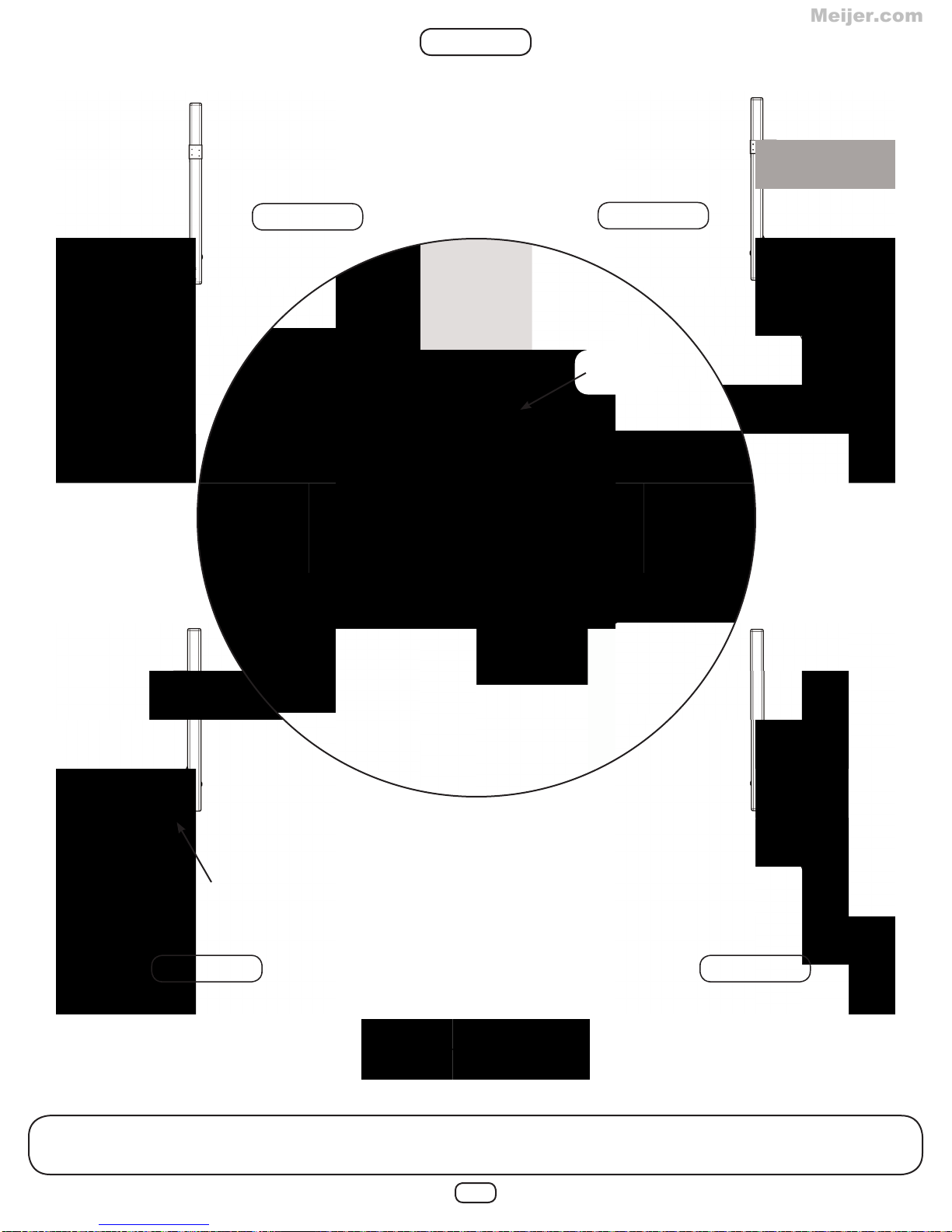
Page 4
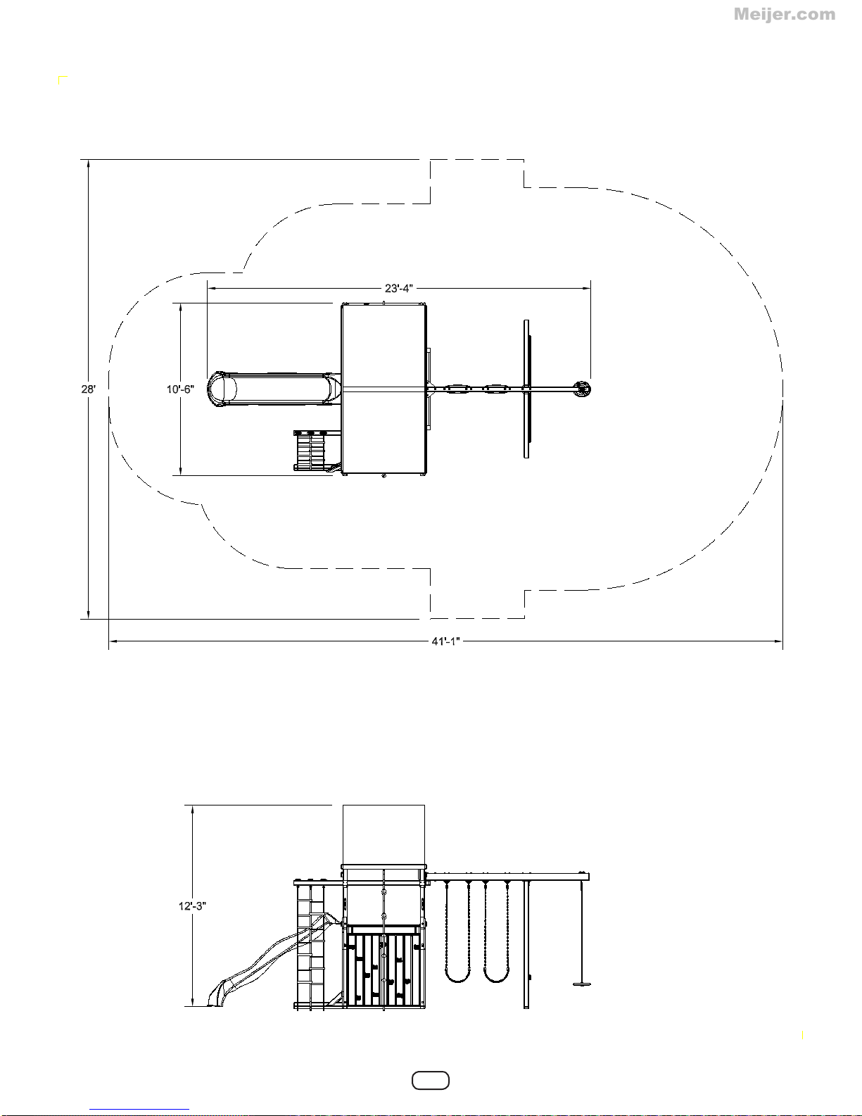
DIMENSIONS
Meijer.com
MINIMUM USE ZONE FOR PLAY EQUIPMENT SHALL EXTEND NO
LESS THAN 72” FROM ALL SIDES OF THE PLAY STRUCTURE.
SWING USE ZONE EXTENDS NO LESS THAN 144”.
4
Page 5
TOOLS REQUIRED
Meijer.com
DRILL 1/2” & 9/16” SOCKET
PHILLIPS BIT CARPENTER
1-1/4” Lag Screw (x20)
2” Lag Screw (x72)
& WRENCH
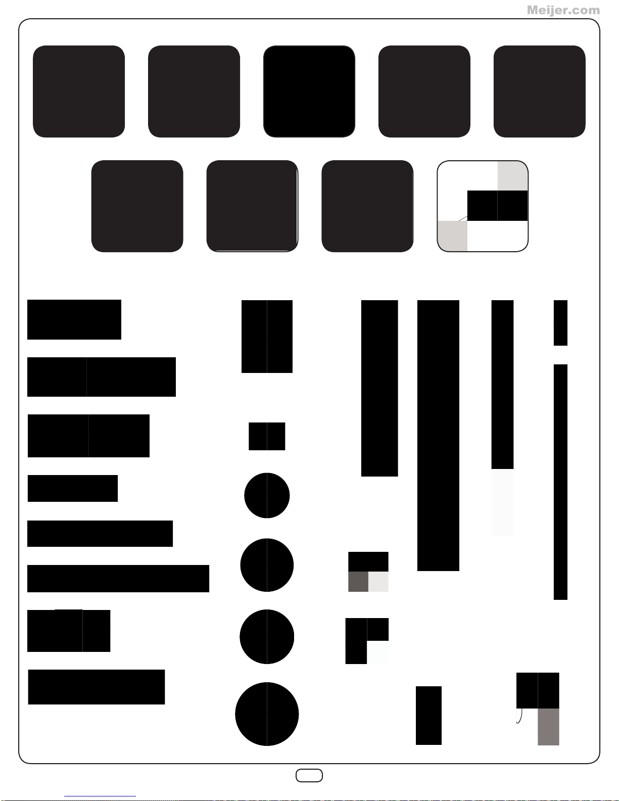
INCLUDED HARDWARE
HAMMER ADJUSTABLE
SQUARE
1/4-20 Weld Nut (x48)
WRENCH
SAFETY GLASSES
1/4”-20 x 2-1/4” Hex Bolt (x48)
5/16”-18 x 3-1/2” Hex Bolt (x2)
TAPE MEASURE
1/8” DRILL BIT
T-20 Bit (x1)
5/16” x 1-1/2” Lag Screw (x6)
1-1/4” Deck Screw (x2)
2” Deck Screw (x8)
2-1/2” Deck Screw (x315)
#14 x 1” Truss Screw (x4)
1/4” x 1-3/4” Pan Screw (x8)
1/4” Loc Washer (x48)
8mm Washer (x48)
1/4” Washer (x8)
5/16” Washer (x28)
3/8” Washer (x24)
3/8” Drill Bit (x1)
5/16” Loc Nut (x20)
T-30 Bit (x1)
3/8” Loc Nut (x24)
1” Rope Staple (x4)1/2” Rope Staple (x6)
5
Page 6

5/16”-18 x 7-3/8” Eye Bolt (x4)
Meijer.com
INCLUDED HARDWARE
3/8”-16 x 5-1/2” Carriage Bolt (x2)
3/8”-16 x 6” Carriage Bolt (x8)
3/8”-16 x 7” Carriage Bolt (x14)
5/16”-18 x 6” Carriage Bolt (x3)
5/16”-18 x 7” Carriage Bolt (x4)
5/16”-18 x 9” Carriage Bolt (x1)
5/16”-18 x 3-3/4” Carriage Bolt (x2)
NOTE:
Included hardware is used for multiple
kits and will result in extra parts.
5/16” Wood Loc Washer (x10) 3/8” Wood Loc Washer (x24)
6
Page 7

INCLUDED COMPONENTS
Meijer.com
4x4 Wrap Loc (x3) 4x4 Shelf Loc (x4) Angle Brace (x4) EZ Frame Bracket (x2)
Beam Brace (x1) L Bracket (x4) Anchor It Strap (x6) Anchor It (x6)
Quick Link (x12) Bolt Cover (x4)Swivel (x1) Climbing Rock (x24)
Steering Wheel w/ Hdw (x1) Super Speedwave Slide (x1) Play Handle (x4) Cargo Net (x1)
7
Page 8

INCLUDED COMPONENTS
Meijer.com
SA 2891
Rock Wall Panel (x3)
XD Swing Seat (x2)Disc Swing (x1) Tire Swing (x1)
SA 2889
Deck Panel A (x2)
SA 2890
Deck Panel B (x1)
33” Coated Chain (x4)
SA 2892
Swing Beam Panel (x1)
SA 2904
Swing Beam Assembly (x1)
Climbing Rope (x2)
ID Tag w/ Hdw (x1) Tarp w/ Hdw (x1)Plan (x1)
8
Page 9

2-
Meijer.com
PF
4523 (4x6x105-1/4 Joist)
PF
4522 ( 4x4x104)
2 -
1-
PF
4521 (4x4x96
1-
PF
4520 (4x4x96
4-
PF
4519 (4x4x73-1/2 Upright)
1 -
PF
4518 (4x4x60
4-
PF
4517 (4x4x51 Post)
Pa.PS~ry
Jla;e;~ry
SWing
·\
4-
PF
4516 (4x4x18-3/8 Upright Support}
1 -
PF
4529 (2x6x76 Racking Support)
1 -
PF
4515 (2x6x60 Base}
Ann Top)
Arm
Bottom)
Beam Support}
BOARD LIST
• 1
1
2-
PF
4514 (2x6x60)
PF
4512 (2x6x53)
9 -
PF
4511 (2x6x46)
2 -
4 -
PF
4510 (2x6x37)
PF
4509 (2x4x120}
2 -
1-
PF
4508 (2x4x85-1/2)
1 -
PF
4507 (2x4x78)
2 -
PF
4506 (2x4x63)
2 -
PF
4505 (2x4x60)
1 -
PF
4536 (2x4x60
2 -
PF
4528 (2x4x53)
0
Rope
Support)
1 -
PF
4504 (2x4x51)
2 -
PF
4527 (2x4x18)
PF
4501 (2x4x18 Angle Support)
2 -
1 -
PF
4526 (2x4x15-3/4 Slide Stake}
2-
PF
4525 (2x2x57-1/2)
9
Page 10
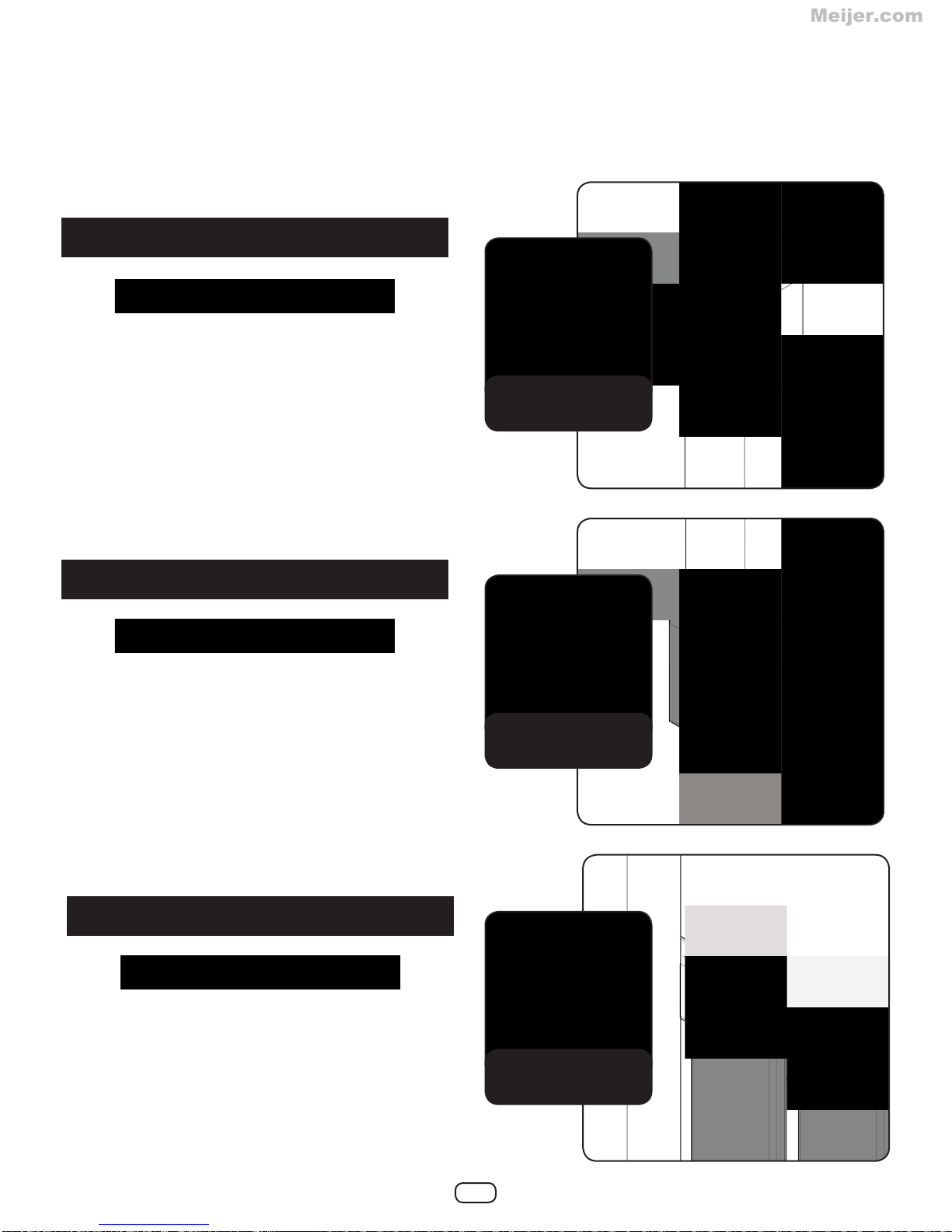
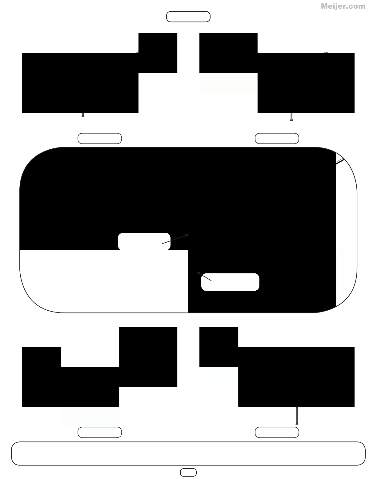
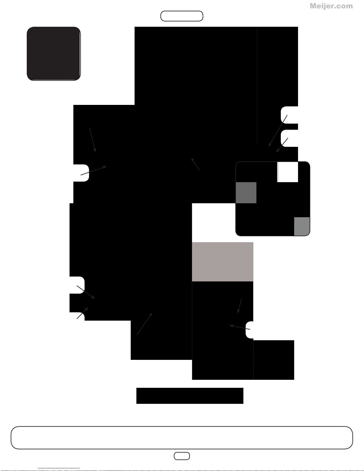
USE THE CORRECT FASTENER
Meijer.com
Use the guides below to help select the correct length, quantity & location of
screws for the board installation.
Avoid splitting your lumber by offsetting your screws at least 3/4” from edge.
All hardware should be driven until fl ush with the surface or no deeper than 1/16”.
2x4 to 4x4 & 4x6
(3) 2-1/2” screws
per attachment point
Pre-Drill 1/8” to
minimize splitting
2x6 to 4x4 & 4x6
(4) 2-1/2” screws
per attachment point
2x4 & 2x6 to 2x4 & 2x6
(2) 2-1/2” screws
per attachment point
Pre-Drill 1/8” to
minimize splitting
Pre-Drill 1/8” to
minimize splitting
10
Page 11
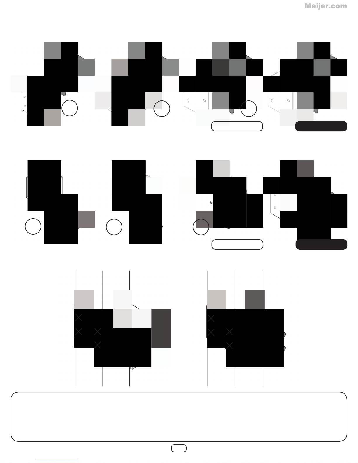
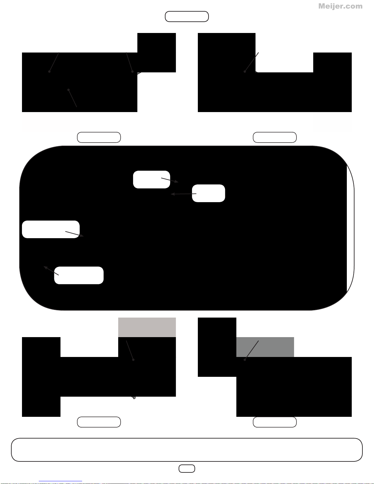
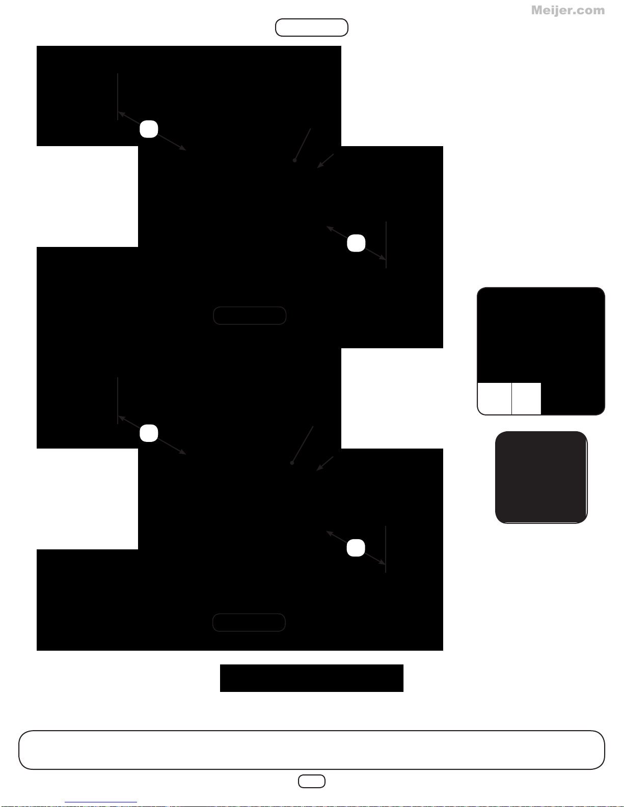
BRACKET INSTALLATION
Meijer.com
Shelf-Loc bracket
1
2 3
CORRECT INCORRECT
Cup-Loc bracket
1
2 3
CORRECT INCORRECT
Bracket mounting
1. Always use lag screws
2. Brackets interlock with each other. NEVER position them in a non-interlocking position.
3. Place lag screws in brackets only where instructed.
Do NOT fi ll in every hole as this will lead to a hardware shortage.
11
Page 12

PF 4517
Meijer.com
4x4x51
STEP 1
2” Lag Screw (x8)
39”
Post A
PF 4517
4x4x51
PF 4517
4x4x51
(2) 2” Lag Screws
per bracket
39”
Post B
39”
Post C
1. Attach brackets as shown. Note the hole orientation of the board.
12
(2) 2” Lag Screws
per bracket
Page 13
PF 4516
Meijer.com
4x4x18-3/8
Upright Support
PF 4519
4x4x73-1/2
Upright
STEP 2
Post A Post C
Support A Support B
3/8”
Loc Nut
3/8”
Washer
3/8 Wood Loc
Washer
3/8”-16 x 6”
Carriage Bolt
PF 4517
4x4x51
x4
Post B
Support C Support D
1. Attach Upright & Upright Support(s) to Post(s) as shown. Note the post & bracket orientation.
13
Page 14
STEP 3
Meijer.com
Support A Support B
5/16 Wood Loc
Washer
5/16”-18 x 7”
Carriage Bolt
x4
Support C Support D
1. Insert hardware into Upright(s) as shown. Note the post & bracket orientation.
14
Page 15
STEP 4
Meijer.com
Support A
Support B
Angle
Brace
x4
HOLD FLUSH
Support D
2” Lag Screw (x24)
1. Slide Angle Brace over bolt and attach as shown. Note the post & bracket orientation.
Support C
15
Page 16
Support A
Meijer.com
STEP 5
3/8 Wood Loc
Washer
3/8”-16 x 7
Carriage Bolt
Support B
x6
5/16” Washer &
Loc Nut
PF 4523
4x6x105-1/4
Joist
5/16” Washer &
Loc Nut
3/8” Loc
Nut
Frame 1
3/8”
Washer
Check to make sure
structure is square
1. Insert hardware into Upright(s) as shown. Note the post & bracket orientation.
2. Place deck joist over bolt(s) and attach as shown.
16
Page 17

Support D
Meijer.com
STEP 6
3/8 Wood Loc
Washer
3/8”-16 x 7
Carriage Bolt
Support C
x6
5/16” Washer &
Loc Nut
Check to make sure
structure is square
PF 4523
4x6x105-1/4
Joist
5/16” Washer &
Loc Nut
3/8” Loc
Nut
Frame 2
3/8”
Washer
1. Insert hardware into Upright(s) as shown. Note the post & bracket orientation.
2. Place deck joist over bolt(s) and attach as shown.
17
Page 18

STEP 7
Meijer.com
1. Attach Angle Brace to deck joist(s) as shown.
x4
2” Lag Screw (x24)
18
Page 19
30”
Meijer.com
STEP 8
PF 4509
2x4x120
FLUSH
30”
Frame 1
30”
Frame 2
PF 4509
2x4x120
FLUSH
30”
Check to make sure
structure is square
2-1/2” Deck Screw (x12)
1. Attach top board as shown. Note the post & bracket orientation.
19
Page 20

STEP 9
Meijer.com
18-3/8”
Angle
Brace
x4
1. Attach L Bracket(s) to deck joist as shown on Frame 1 & Frame 2.
20
OFFSET 1” FROM
TOP OF DECK JOIST
1-1/4” Lag Screw (x8)
Page 21

(2) PF 4511
Meijer.com
2x6x46
STEP 10
Check to make sure
structure is square
FLUSH TOP
SURFACES
1. Attach boards as shown.
x4
1-1/4” Lag Screw (x12)
21
Page 22

STEP 11
Meijer.com
TIGHT TO
BOTTOM OF
JOIST
PF 4514
2x6x60
1. Attach board as shown.
2-1/2” Deck Screw (x8)
22
Page 23
Check to make sure
Meijer.com
structure is square
STEP 12
3/8”-16 x 5-1/2”
Carriage Bolt
3/8 Wood Loc
Washer
3/8” Washer
3/8” Washer
3/8” Loc Nut
PF 4515
2x6x60
Base
3/8”-16 x 7”
Carriage Bolt
3/8” Loc Nut
Accessory Arm Bottom
1. Attach boards as shown.
3/8 Wood Loc
Washer
PF 4520
4x4x96
2-1/2” Deck Screw (x8)
23
Page 24
STEP 13
Meijer.com
FLUSH
(2) PF 4501
2x4x18
Angle Support
FLUSH
BACKSIDE
3-1/2
FLUSH
2-1/2” Deck Screw (x10)
1. Laminate boards and attach as shown.
24
Page 25
TIP: Flex bracket(s) to make
Meijer.com
installation of 4x4 easier
STEP 14
FLUSH WITH
POST
PF 4521
4x4x96
Accessory Arm T op
1. Attach board as shown.
2” Lag Screw (x8)
25
Page 26

STEP 15
Meijer.com
PF 4506
2x4x63
(2) 2-1/2” Deck
Screws per joint
FLUSH
PF 4536
2x4x60
Rope Support
(3) 2-1/2” Deck
Screws per joint
FLUSH
PF 4506
2x4x63
(2) 2-1/2” Deck
Screws per joint
Check to make sure
structure is square
1. Attach boards as shown.
2-1/2” Deck Screw (x14)
26
Page 27

STEP 16
Meijer.com
2-3/4” gap from
post
1/2” gap
1/2” gap
SA 2889
Deck Panel A
SA 2890
Deck Panel B
2-3/4” gap from
post
SA 2889
Deck Panel A
2-1/2” Deck Screw (x48)
1. Attach deck panel(s) as shown.
27
Page 28

FLUSH
Meijer.com
STEP 17
PF 4505
2x4x60
(2) PF 4527
2x4x18
(4) 2-1/2” Deck
Screws per board
9”
45”
FLUSH
1-3/4” gap
typical
(4) PF 4510
2x6x37
2-1/2” Deck Screw (x30)
1. Attach boards as shown.
28
Page 29

( )
Meijer.com
STEP 18
SA 2892
Swing Beam
Panel
2-1/2” Deck Screw (x12)
1. Attach Swing Beam Panel as shown.
29
CJ
45”
Page 30

STEP 19
Meijer.com
TIP: Flex bracket(s) to make
installation of 4x4 easier
2” Lag Screw (x8)
5/16”-18 x 3-1/2”
Hex Head Bolt
5/16”
Washer
Beam Brace
PF 4518
4x4x60
Swing Beam
Support
5/16”
Washer
5/16”
Loc Nut
FLUSH WITH
POST
2-1/2” Deck Screw (x12)
1. Attach Beam Brace to Swing Beam Support as shown.
2. Attach Swing Beam Support board as shown.
30
Page 31

PF 4504
Meijer.com
2x4x51
FLUSH BOTTOM
EDGES
STEP 20
PF 4505
2x4x60
(2) 2-1/2” Deck
Screws per joint
PF 4508
2x4x85-1/2
59-3/4”
2-1/2” Deck Screw (x19)
1. Attach boards as shown.
31
Page 32

2-1/2” Deck Screw (x22)
Meijer.com
STEP 21
EZ Frame
Bracket
FLUSH EDGES
26-1/8”
(2) PF 4522
4x4x104
PF 4507
2x4x78
102-1/4”
1. Attach EZ frame bracket(s) to boards as shown.
2. Attach board as shown.
32
Page 33

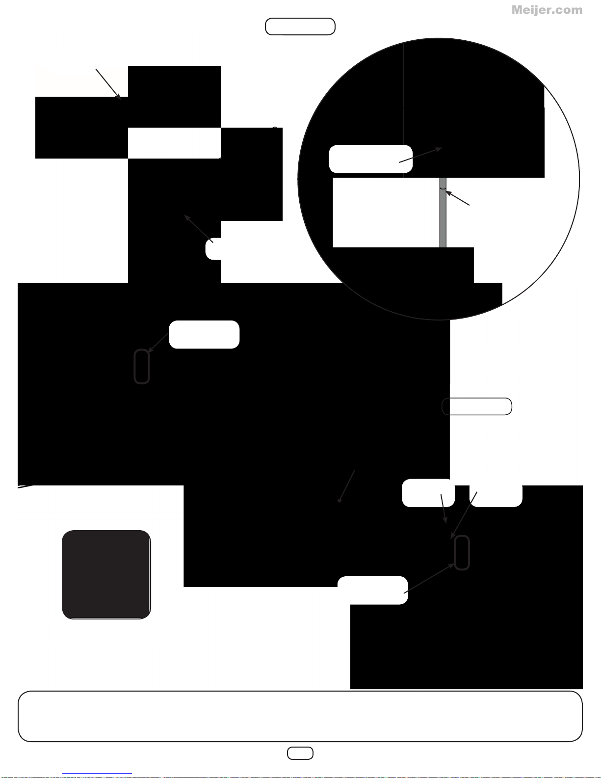
STEP 22
Meijer.com
SA 2904
Swing Beam
Assembly
5/16”
Loc Nut
5/16”-18 x 9”
Carriage Bolt
Tower connection
5/16”-18 x 6”
Carriage Bolt
5/16” Wood
Loc Washer
5/16”
Washer
2-1/2” Deck
Screw
A-Frame connection
5/16”-18 x 6”
Carriage Bolt
5/16” Wood
Loc Washer
5/16”
Washer
5/16”
Loc Nut
2-1/2” Deck Screw (x4)
1. Attach Swing Beam Assembly to A-Frame as shown.
2. Attach Swing Beam Assembly to tower as shown.
33
Page 34

STEP 23
Meijer.com
2-1/2” Deck Screw (x36)
1. Attach rock wall panels as shown.
3/8” gap
typical
(3) SA 2891
Rock Wall
Panel
34
Page 35

STEP 24
Meijer.com
Note:
Screw through front
boards into 2x2(s).
(2) 2-1/2” Deck
Screws per joint
(2) PF 4528
2x4x53
(2) PF 4525
2x2x57-1/2
(9) PF 4512
2x6x53
2-1/2” Deck Screw (x72)
1. Assemble rock wall and attach to unit as shown.
PF 4529
2x6x76
Racking
Support
35
Page 36
STEP 25
Meijer.com
PF 4514
2x6x60
TIGHT TO
BOTTOM OF
JOIST
2-1/2” Deck Screw (x8)
1. Attach board as shown.
36
Page 37

STEP 26
Meijer.com
1/4-20 T-Nut
1/4” Loc
Washer
Climbing
Rock
Note:
Maximum hardware
thickness is 1-1/2”
8mm Washer
1/4”-20 x 2-1/4
Hex Head Bolt
1. Mark locations of Climbing Rocks on both rock walls and drill a 3/8” hole (Avoid rear supports).
2. Attach climbing rocks as shown.
3. Make sure Climbing Rocks and rock wall connections are secure before use.
37
Page 38

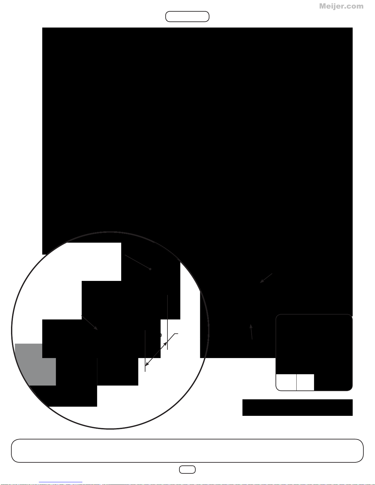
STEP 27
Meijer.com
x2
1” Rope
Staple
1. Insert rope(s) thru hole in top support board(s) and tie an overhand knot.
2. Tie an overhand knot approximate every 18” for hand grips, for a total of 5 knots.
3. Pull bottom of rope under Rock Wall, attach one rope staple, fold back onto itself and attach 2nd staple.
x2
38
Page 39

SA 2890
Meijer.com
Deck Panel B
STEP 28
Swivel
Underdeck View
5/16”-18 x 3-3/4”
Carriage Bolt
5/16 Wood Loc
Washer
1
5/16”
Washer
5/16”
Loc Nut
2
Top deck view
1. Center the Swivel under the deck, mark hole locations and drill two 3/8” holes.
2. Insert hardware into deck panel (from top side) as shown.
3. Attach swivel as shown.
39
3
Underdeck View
Page 40

STEP 29
Meijer.com
5/16”-18 x 7-3/8”
Eye Bolt
x4
5/16”
Washer
5/16”
Loc Nut
Tire Swing
1. Attach hardware to Tire Swing as shown.
40
Page 41

STEP 30
Meijer.com
33” Coated Chain
Quick Link
x4
Quick Link
“Open”
Note:
For correct installation, the thread
must be at the bottom
Quick Link
“Closed”
Tighten Quick Link(s)
1. Attach hardware as shown.
2. Attach Tire Swing to swivel.
41
Page 42

STEP 31
Meijer.com
5/16”-18 x 3”
Carriage Bolt
5/16” Loc Nut
Cap
5/16” Washer
Steering Wheel
Spacer
Note:
If lumber is greater than 2” thick, you will need to
counterbore the hole appropriately.
1. Choose location for the Steering Wheel and drill one 3/8” hole.
2. Assemble Steering Wheel as shown.
42
Page 43

x3
Meijer.com
STEP 32
5/16”
Loc Nut
5/16”
Washer
1
Cargo Net
2” Deck
Screws
Bolt Cover
1/2” Rope
Staple
2
3
x3
1. Insert eye bolt(s) into Accessory Arm Top and fasten as shown.
2. Attach Bolt Cover(s) over each eye bolt end as shown.
3. Pull bottom of rope under Accessory Arm Bottom, attach one rope staple, fold back onto itself and
attach 2nd staple.
x3
43
Page 44

STEP 33
Meijer.com
1/4”
Washer
1/4 x 1-3/4”
Pan Screw
11”
ABOVE DECK
x4
1-3/4” Pan Screw (x8)
1. Mount Safety Handle(s) on posts as shown.
44
Page 45

STEP 34
Meijer.com
HOLD THE T ARP
END 1” FROM TOP
OF BOARD
1
2
Tarp Snap Screw (x10)
1. Wrap one end of the tarp around one support and tap the head of the snap(s) to leave an indent.
2. Install the Snap Screws at the indentations and attach the tarp to them.
3. Repeat for opposite end, pulling taught to elminate any major wrinkles.
45
Page 46

STEP 35
Meijer.com
Tighten Quick Link(s)
Quick Link
XD Swing Seat
Quick Link
“Open”
Note:
For correct installation, the thread
must be at the bottom
Quick Link
“Closed”
1. Attach Quick Link(s) to swing hangers as shown.
2. Attach XD Swing Seat(s) to Quick Link(s).
46
Page 47

STEP 36
Meijer.com
5/16”
Loc Nut
5/16”
Washer
1. Insert eye bolt into swing beam and fasten as shown.
2. Attach Bolt Cover over eye bolt end as shown.
2” Deck
Screws
Bolt Cover
Disc Swing
47
Page 48

STEP 37
Meijer.com
1” Truss
Screws
1. Attach slide as shown.
1-1/4” Deck
Screws
2”
Grade
1-1/4” Deck
Screws
PF 4526
2x4x15-3/4
Slide Stake
1-1/4” Deck Screw (x2)1” Truss Screw (x4)
48
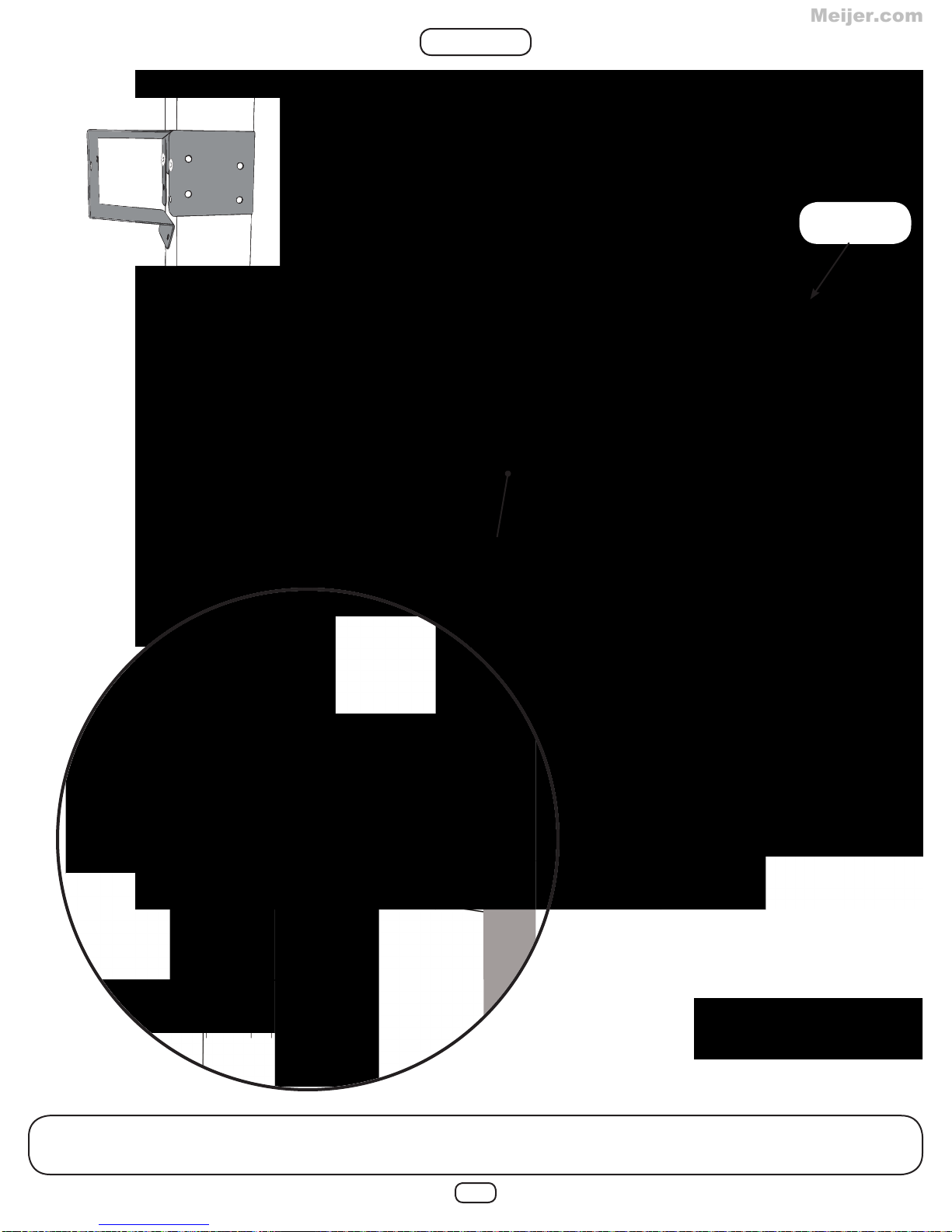
Page 49
STEP 38
Meijer.com
Fold up
Anchor-It
Strap
Anchor-It
5/16”
Washer
1-1/2” Lag
Screw
5/16 x 1-1/2” Lag Screw (x6)
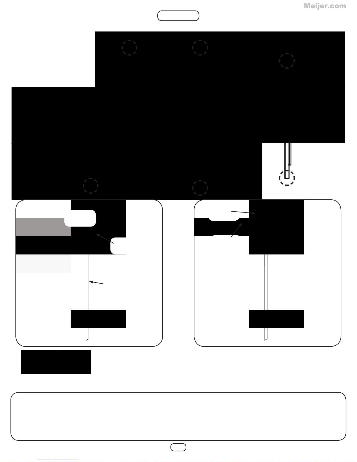
1. Place swing set in fi nal location and mount Anchor-It(s) at locations circled above.
2. Twist the Anchor-It into the ground until only the loop is exposed.
3. Place Anchor-It Strap thru loop, fold the ends together and attach to the unit as shown.
Note: Keep as little play as possible using any of the holes in the strap that work best.
49
Page 50

STEP 39
Meijer.com
(..____
_
___.)
1/2” Pan Screw (x2)
1. Attach ID Tag as shown.
50
CJ
0
INTENDED
FOR
USE
BY
R£SIDEHT1Al
P
AFIA
SER
Y IO!Wcs
El.HOGAIWSO
SflA.fMENT
!i!f
lrt
WI
53StS
0
CHUJREN
USE
ONLY
USADOI'OR
DE
EOAO
~
f.
Olive
LA5535
F~AGES2-IOYEARS
FOR
HOME
/
OISENADo
NKls
ENTRE2
PARAUSO
EN
llfNCW.lNCAMENTE
~ALVTUSATIONPARDES
ENf"NIITS0£2,\IO/\HS
USAG
E
flf.slofN11EIA'~
~·"~
121211arberry
.bne'sYille,
www..awl~shde.eom
Page 51

Meijer.com
51
Page 52

R
Meijer.com
R
800•888•1232
Got Questions? We’ve got answers!
Call our Customer Support Representatives
Available Monday - Friday, 7am - 5pm (CST)
Weekend support available April through Labor Day
Also available on Memorial Day, Fourth of July & Labor Day
Technical Support from experienced Swing-N-Slide Customer Service
Representatives who have actually built a swing set themselves.
© Playcore Inc. 2012 Printed in USA
 Loading...