

Page 1

NE 4273
R
Picnic Table
check out http://www.swing-n-slide.com
for updates to these instructions.
ASSEMBLY INSTRUCTIONS
Swing•N•Slide • 1212 Barberry Drive • Janesville, Wisconsin 53545
Visit our web site at: www.swing-n-slide.com or call us at 1-800-888-1232
Page 2

R
Safety Checklist for Swing-N-Slide Play Sets and Accessories
Observing the following statements and warnings reduces the likelihood of serious or fatal injury
Installation Safety – Have You:
Consulted the assembly instructions supplied with your particular model?
Noted this accessory is to be used only on Swing•N•Slide approved designs? (Do not alter its design or add/remove components.)
Made sure all hardware is tightened securely? (Supplied bolt covers must also be fastened securely.)
Using a hacksaw, cut off all protruding threaded ends of bolts and other fasteners and remove any sharp edges with
a metal file as needed?
Placed the equipment on level ground, not less than six feet (1.8 meters) from any structure or obstruction such as a fence, garage,
house, overhanging branches, laundry lines, or electrical wires?
Made sure home playground equipment is not installed over concrete, asphalt, packed earth or any other hard surface? (A fall onto
a hard surface can result in serious injury to the equipment user.)
Verified that suspended climbing ropes, chain,or cable are secured at both ends?
Consulted in assembly instructions of your particular model for minimum use zones?
Followed all anchoring and shock absorbing surfacing requirements on the back of this sheet as they apply?
Made sure not to allow children to use equipment until it is properly installed?
Operating Safety – Have You:
Determined that on-site adult supervision is provided for children of all ages?
Warned children the following before allowing them to use the equipment?
Not to walk close to, in front of, behind or between moving items.
Not to twist swing or any other accessory chains or ropes or loop them over the top support bar since this will reduce the
strength of chain or rope.
Not to swing empty seats or other accessories.
Be sure to sit in the center of the swing seat and other accessories with full weight on the seat.
Not to attach items to the playground equipment that are not specifically designed for use with the equipment such as but not
limited to, jump ropes, clotheslines, pet leashes, cables and chain. They may cause a strangulation hazard.
Not to use equipment in a manner other than intended.
Not to get off equipment while it is in motion.
Not to climb on the equipment when it is wet.
Determined that only one child per planned occupant seat should be allowed on this set at one time.
Determined children must be dressed appropriately for play. Avoid clothing with draw strings and loose fitting clothes which
could become entangled or snagged on equipment.
Determined that suspended climbing ropes, chain, or cable cannot be looped back upon itself.
Read and understood the following warning regarding the use of two and four passenger lawn swings?
Warning: Lawn Swings are designed for use by children over two years of age. Use by children under the age of two can result
in entrapment between the seats and back areas. Never place children in a rearward facing position or with legs between the
seat and backrest because the child’s body may pass through the opening causing entrapment of the child’s head.
Safety Maintenance – Have You Determined to:
Check all nuts and bolts twice monthly during the usage season for tightness and tighten as required? (It is
particularly important that this procedure be followed at the beginning of each season.)
To prevent the deterioration of materials, remove plastic swing seats and other plastic accessories and take indoors? (Do not
use when the temperature drops below 0° F.)
Oil all metallic moving parts monthly during usage period?
Check all hardware and equipment for sharp edges twice monthly during usage season? (Replace when
necessary. It is especially important to do this at the beginning of each new season.)
Check swing seats, chains, ropes and cables monthly during usage season for evidence of deterioration? Severe rusting or excessive
wear, especially near the top swing hanger or at the seat connection are evidence of chain deterioration. Cracks in the protective plastic
sleeve or seat itself are also signs of deterioration. If any of these conditions exist, call 1-800-888-1232 to order replacement accessories.
Sand rusted metal parts and repaint using non-lead based paint.
Disposal Instructions
When the equipment is taken out of service, it must be disassembled and disposed of in such a way that no unreasonable hazards
will exist at the time the set is discarded.
Important!
Save this instruction sheet in the event the manufacturer needs to be contacted.
Additional Safety Instructions for all Swing-N-Slide Playground Equipment.
2
Page 3
This product is intended for single family home/residential use only and not intended for use in any public setting.
According to ASTM requirements, all kits must be anchored to the ground and, if the unit has a climbing rope, the rope end must be anchored to the ground. If soil conditions
permit stakes to be pulled out easily, cementing into ground is necessary.
• To anchor the unit to the ground, Follow the instructions included in this plan for applying Anchor-It devices to your unit, or use 2" x 4" x 18" (45mm x 95mm x 457mm) pressuretreated stakes. Pound stakes into ground at least 12" (305mm) at all inside corners of the posts (including A-frame legs and climbing unit posts). Attach with four (4) 16D (3-1/2")
galvanized nails per stake into each 4" x 4" (95mm x 95mm) post.
• If the unit has a climbing rope, anchor the rope end.
• Once the unit is completely assembled and before children are allowed to play on it, proper shock-absorbing surfacing material must be installed. This may be accomplished by
using loose-fill materials at a sufficient depth. The Consumer Product Safety Commission “Handbook for Public Playground Safety” lists the following materials and required
depths that are sufficient for home/residential application. For fall height protection up to 9 ft. (2.742m) [recommended for Swing•N•Slide kits]:
Double Shredded Bark Mulch 9" (229mm)
These depths were derived from the CPSC Handbook. Swing•N•Slide has not done independent tests to determine these required depths.
When properly installed, shock absorbing material will completely cover the horizontal baseboards on climbing units. This protective surfacing must extend a minimum of 6 ft.
(1.828m) in all directions from the perimeter of the equipment or from the outermost edges of any component. For example, a slide extending beyond the platform must have
protective surfacing at least 6 ft. (1.828mm) out from both sides as well as the end. For swings, the protective surface must extend at least 14 ft. (6m) out from both the back and
front of the swing when the swing is in its rest position.
Placement in any public setting constitutes a misuse of this product.
ADDITIONAL REQUIRED SAFETY INSTALLATION INSTRUCTIONS
LOOSE FILL MATERIAL REQUIRED (UNCOMPRESSED) DEPTH1in. (mm)
Wood Mulch 9" (229mm)
Uniform Wood Chips 12" (305mm)
Fine Sand 12" (305mm)
Fine Gravel 12" (305mm)
IMPORTANT!
Notes:
3
Page 4

ASSEMBLY INSTRUCTIONS
(4) Shutters
(2) 1'' x 4'' x 14''
(8) 1'' x 4'' x 22-1/4''
(18) 1'' x 4'' x 40''
(2) 1'' x 6'' x 46'' Drape Cut
(2) 1'' x 6'' x 47-1/2'' Drape Cut
(2) 1'' x 6'' x 47-1/2''
CUT (2) 1'' x 6'' x 46'' Drape Cut Boards As Shown
CUT (2) 1'' x 6'' x 47-1/2'' Drape Cut Boards As Shown
15-5/16''
39-9/16''
HARDWARE INCLUDED
(4) 3/4'' Truss Screw
(64) 2" deck screws
(87) 1-1/4" deck screws
(36) 2-1/2" deck screws
LUMBER LIST
NOTE:
SWING-N-SLIDE MANUFACTURES
MULTIPLE KITS FROM A CENTRAL
WOOD PACK. DUE TO THIS YOU MAY
RECEIVE EXTRA BOARDS THAT THIS
PROJECT DOES NOT REQUIRE.
RETAIN THIS LUMBER FOR FUTURE
PROJECTS.
LUMBER MODIFICATION
4
Page 5

TOOLS REQUIRED
HAMMER
PHILLIPS BIT
ELECTRIC DRILL
CIRCULAR SAW
SQUARE
TAPE MEASURE
SAFETY GLASSES
& DUST MASK
PICNIC TABLE COMPONENTS
(2) Table Supports
Picnic Table
Plan
(1) Plan
5
Page 6

Picnic Table Assembly Instructions
Fig. 1
2''
Fig. 1a
(10) 1'' x 4'' x 40''
(7)
1-1/4'' screws
per board
2''
'
'
2
/
1
-
7
1
(10)
2'' screws
'
'
4
1
x
'
'
4
x
'
'
1
'
'
4
/
1
-
2
'
'
4
1
x
'
'
4
x
'
'
1
(10)
2'' screws
'
'
4
/
3
-
1
2''DeckScrew
Table Assembly
1. Assemble the Picnic Table Top as shown in (Fig. 1). Note: Make certain to install hardware in the manner shown as
this will make steps later on in the assembly process much easier.
2. Install the (2) Table Support Boards as shown in (Fig. 1a).
'
'
4
/
1
-
2
1-1/4''DeckScrew
6
Page 7

Picnic Table Assembly Instructions
2''
(4) 1'' x 4'' x 40''
(7)
1-1/4'' screws
per board
2''
(4) 1'' x 4'' x 40''
2''
'
'
7
(7)
1-1/4'' screws
per board
Fig. 2
2''
'
'
7
Fig. 2a
x
4
(2) 1'' x 4'' x 22-1/4''
(6)
1-1/4'' screws
per board
1-1/4''DeckScrew
Bench and Leg Assemblies
1. Assemble the Picnic Table Benches as shown in (Fig. 2). Note: Make certain to install hardware in the manner
shown as this will make steps later on in the assembly process much easier.
2. Assemble the (4) Table Legs as shown in (Fig. 2a).
7
Page 8

Picnic Table Assembly Instructions
'
1'' x 6'' x 15-5/16''
4'
Fig. 3
(2) 1''
x
4''
x
Drape Cut Board
2-1/
2
(2)
2'' screws
per joint
(
2
)
1
'
'
x
4
'
'
x
2
2
-
1
/
4
'
'
x
2
Fig. 3a
21-1/2''
65˚
1'' x 6'' x 47-1/2''
UNDERSIDE VIEW
FLUSH
6-5/8''
65˚
(3)
2'' screws
per joint
16-3/16''
6-5/8''
2''DeckScrew
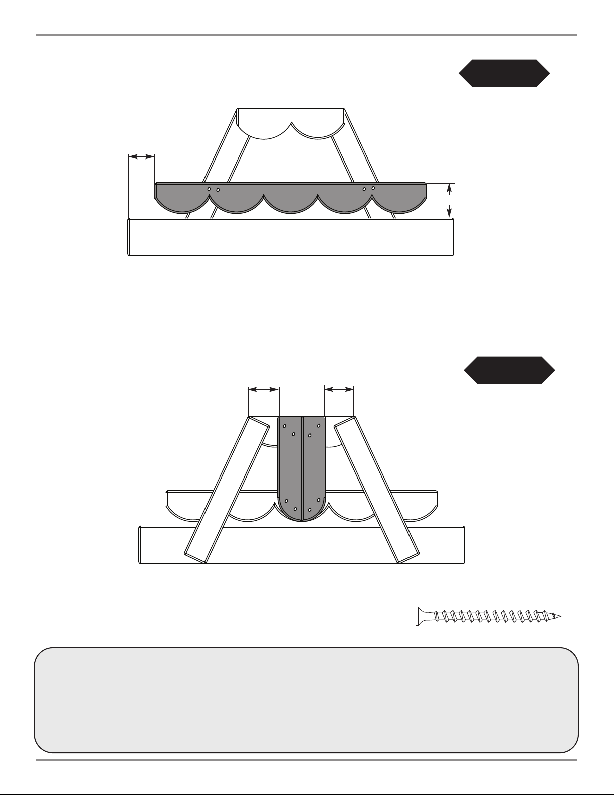
Pinic Table End Assemblies
1. Assemble the (2) Picnic Table Ends as shown in (Fig. 3).
Note: The underside of this assembly is illustrated in (Fig. 3a) to make the necassary measurements more clear.
FLUSH
8
Page 9
3-15/16''
1'' x 6'' x 39-9/16''
Drape Cut Board
Picnic Table Assembly Instructions
Fig. 4
x
2
(2)
2'' screws
per joint
5-1/8''
Pinic Table End Assemblies Cont.
4-7/16''
FLUSH
(2) Shutters
4-7/16''
(2)
2'' screws
per joint
Fig. 4a
x
2''DeckScrew
2
1. Install Drape Cut Boards as shown in (Fig. 4).
2. Install (2) Shutters per Table End as shown in (Fig. 4a).
9
Page 10

Picnic Table Assembly Instructions
(2)
2-1/2'' screws
per board
FLUSH
Fig. 5
(2)
2-1/2'' screws
per board
FLUSH
2-1/2''DeckScrew
Fig. 5a
FLUSH
2-1/2'' screws
(2)
per board
(2)
2-1/2'' screws
per board
FLUSH
Picnic Table Final Assembly
1. Attach Picnic Benches to one of the Picnic Table Ends as shown in (Fig. 5).
2. Attach opposite ends of Picnic Benches to remaining Picnic Table End as shown in (Fig. 5a).
10
Page 11

Picnic Table Assembly Instructions
FLUSH
(2)
2-1/2'' screws
per joint
Fig. 6
FLUSH
FLUSH
2-1/2''DeckScrew
UNDERSIDE VIEW
(2) Table Supports
(2)
3/4'' Truss Head screws
per Support
Fig. 6a
3/4''TrussHead Screw
Picnic Table Final Assembly Cont.
1. Attach Picnic Table Top as shown in (Fig. 6).
2. Install (2) Table Supports as shown in (Fig. 6a).
11
Page 12

Questions???...
R
Call our Customer Service Department
at 1-800-888-1232
© PlayCore Inc. 2009 Printed In USA LA 6101
 Loading...