

Page 1
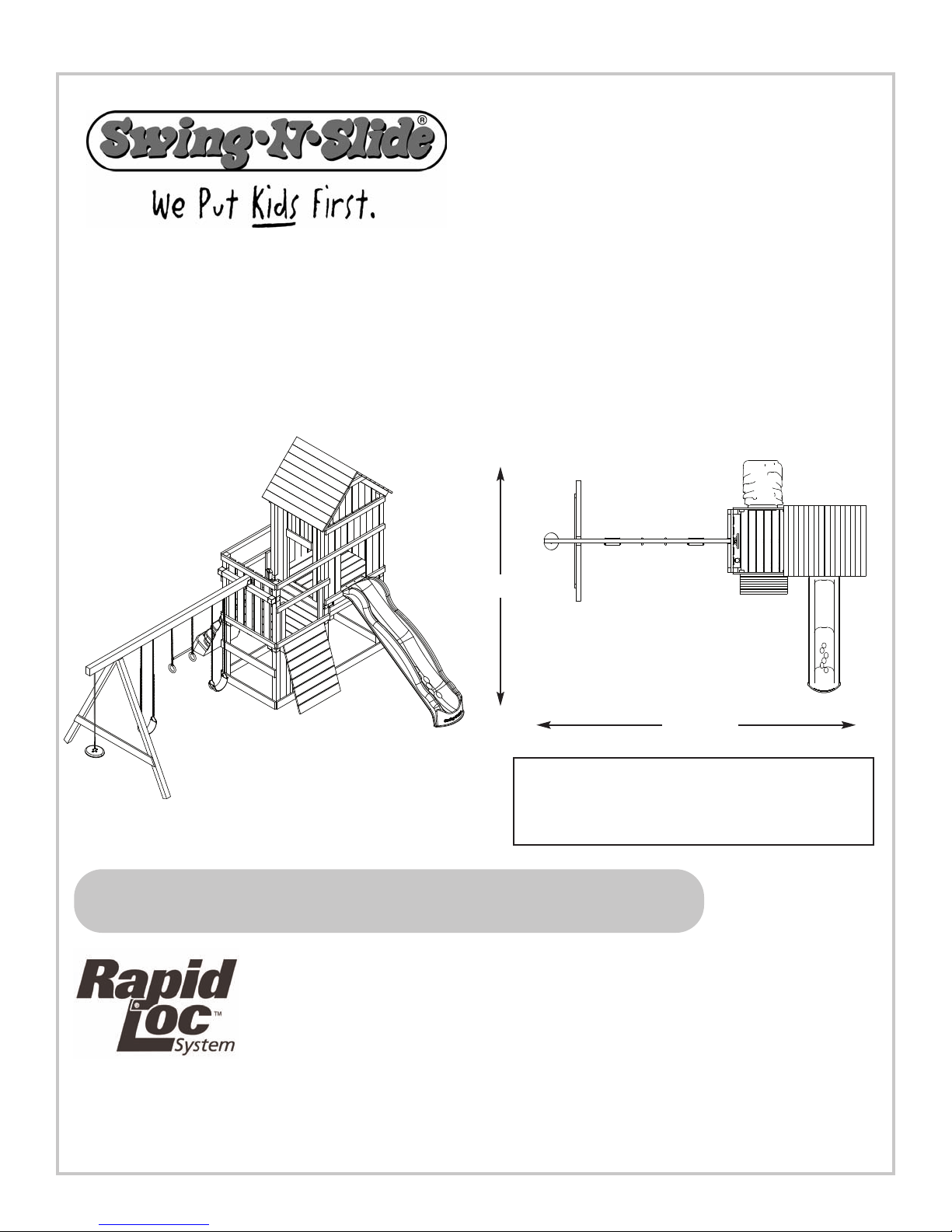
Kodiak
PROJECT 513
NE 5010
TM
30'
No. of Children: Up to 10
Min. Use Zone: 30' x 32'
Set Dim. 20'W x 17'L
Est. Building Time: 5-10 hr.
check out http://www.swing-n-slide.com/planupdates.htm
for updates to these instructions.
32'
x 13'H
ASSEMBLY INSTRUCTIONS
Swing•N•Slide • 1212 Barberry Drive • Janesville, W
isit our web site at:
V
.swing-n-slide.com
www
or call us at
isconsin 53545
1-800-888-1232
Page 2

Safety Checklist for Swing-N-Slide Accessories
R
bserving the following statements and warnings reduces the likelihood of serious or fatal injury
O
Installation Safety – Have You:
Consulted the assembly instructions supplied with your particular model?
Noted this accessory is to be used only on Swing•N•Slide approved designs? (Do not alter its design or add/remove components.)
Made sure all hardware is tightened securely? (Supplied bolt covers must also be fastened securely.)
Using a hacksaw, cut off all protruding threaded ends of bolts and other fasteners and remove any sharp edges with
a metal file as needed?
Placed the equipment on level ground, not less than six feet (1.8 meters) from any structure or obstruction such as a fence, garage,
house, overhanging branches, laundry lines, or electrical wires?
Made sure home playground equipment is not installed over concrete, asphalt, packed earth or any other hard surface? (A fall onto
a hard surface can result in serious injury to the equipment user.)
Verified that suspended climbing ropes, chain,or cable are secured at both ends?
Consulted in assembly instructions of your particular model for minimum use zones?
Followed all anchoring and shock absorbing surfacing requirements later in this guide as they apply?
Made sure not to allow children to use equipment until it is properly installed?
Operating Safety – Have You:
Determined that on-site adult supervision is provided for children of all ages?
Warned children the following before allowing them to use the equipment?
Not to walk close to, in front of, behind or between moving items.
Not to twist swing or any other accessory chains or ropes or loop them over the top support bar since this will reduce the
strength of chain or rope.
Not to swing empty seats or other accessories.
Be sure to sit in the center of the swing seat and other accessories with full weight on the seat.
Not to attach items to the playground equipment that are not specifically designed for use with the equipment such as but not
limited to, jump ropes, clotheslines, pet leashes, cables and chain. They may cause a strangulation hazard.
Not to use equipment in a manner other than intended.
Not to get off equipment while it is in motion.
Not to climb on the equipment when it is wet.
Determined that only one child per planned occupant seat should be allowed on this set at one time.
Determined children must be dressed appropriately for play. Avoid clothing with draw strings and loose fitting clothes which
could become entangled or snagged on equipment.
Determined that suspended climbing ropes, chain, or cable cannot be looped back upon itself.
Read and understood the following warning regarding the use of two and four passenger lawn swings?
Warning: Lawn Swings are designed for use by children over two years of age. Use by children under the age of two can result
in entrapment between the seats and back areas. Never place children in a rearward facing position or with legs between the
seat and backrest because the child’s body may pass through the opening causing entrapment of the child’s head.
Safety Maintenance –
Check all nuts and bolts twice monthly during the usage season for tightness and tighten as required? (It is
ticularly important that this procedure be followed at the beginning of each season.)
par
event the deterioration of materials, r
o pr
T
use when the temperature drops below 0° F.)
Oil all metallic moving par
Check all har
necessary. It is especially important to do this at the beginning of each new season.)
Check swing seats, chains, r
, especially near the top swing hanger or at the seat connection ar
wear
sleeve or seat itself are also signs of deterioration. If any of these conditions exist, call 1-800-888-1232 to order replacement accessories.
Have You Determined to:
emove plastic swing seats and other plastic accessories and take indoors? (Do not
ts monthly during usage period?
e and equipment for sharp edges twice monthly during usage season? (Replace when
dwar
opes and cables monthly during usage season for evidence of deterioration? Severe rusting or excessive
e evidence of chain deterioration. Cracks in the pr
otective plastic
Disposal Instr
When the equipment is taken out of service, it must be disassembled and disposed of in such a way that no unreasonable hazards
will exist at the time the set is discarded.
uctions
Important!
Additional Safety Instructions for all Swing-N-Slide Playground Equipment.
Save this instr
uction sheet in the event the manufactur
er needs to be contacted.
2
Page 3
SAFETY INSTRUCTIONS
INSTRUCCIONES DE SEGURIDAD
INSTRUCTIONS CONCERNANT LA SÉCURITÉ
IMPORTANT!
etting. Placement in any public setting constitutes a misuse of this product.
s
This product is intended for single family residential use only and not intended for use in any public
REQUIRED SAFETY INSTALLATION INSTRUCTIONS
• Once the unit is completely assembled and before children are allowed to play on it, proper shock-absorbing surfacing material
must be installed.
“Handbook for Public Playground Safety” lists the following materials and required depths that are sufficient for home/residential application.
For fall height protection up to 9 ft. (2.742m) [recommended for Swing•N•Slide kits]:
LOOSE FILL MATERIAL REQUIRED DEPTH 1INCH (mm)
Wood Mulch 9" (229mm)
Double Shredded Bark Mulch 9" (229mm)
Uniform Wood Chips 12" (305mm)
Fine Sand 12" (305mm)
Fine Gravel 12" (305mm)
These depths were derived from the CPSC Handbook. Swing•N•Slide
1
has not done independent tests to determine these required depths.
ŃIMPORTANTE!
ningún lugar público. El ubicarlo en cualquier lugar público constituye mal uso de este producto.
This may be accomplished by using loose-fill materials at a sufficient depth. The Consumer Product Safety Commission
When properly installed, shock absorbing material will completely
(UNCOMPRESSED)
cover the horizontal baseboards on climbing units. This protective
surfacing must extend a
from the perimeter of the equipment or from the outermost edges of
any component. For example, a slide extending beyond the platform
must have protective surfacing at least 6 ft. (1.828m) out from both
sides as well as the end. For swings, the protective surface must
at least 14 ft. out from both the back and front of the swing
extend
when the swing is in its rest position.
minimum of 6 ft. (1.828m) in all directions
Este producto es para ser usado por una sola familia en uso residential y no para usarse en
INSTRUCCIONES REQUERIDAS PARA LA INSTALACIÓN CON SEGURIDAD
• Una vez que se haya armado la unidad completamente y antes que se permita a los niĖos que la usen, se debe instalar un material
que amortigüe para la superficie del suelo. Esto se puede conseguir usando materiales que llenen flojamente a una profundidad suficiente.
El “Folleto para la Seguridad Pública en Campos de Recreo” de la Comisión de Seguridad de Producto al Cliente, permite los siguientes
materiales y las profundidades requeridas que sean lo suficiente para una aplicación en situaciones de residencias. Para protección contra
caídas se necesita hasta 9 pies (2,742m) [recomendadas para los conjuntos Swing•N•Slide]:
MATERIALDE APLICACIÓN FLOJA PROFUNDIDAD REQUERIDA1PULGADA
Viruta de madera 9" (229mm)
Viruta trizada de corteza de árbol 9" (229mm)
Trozos pequeĖos uniformes
de madera 12" (305mm)
Arena fina 12" (305mm)
Grava fina 12" (305mm)
1
Estas profundidades fueron derivadas del folleto CPSC. Swing•N•Slide no
ha hecho pruebas independientes para determinar las requeridas profundidas.
mm (SIN SER COMPRIMIDA)
Cuando se instale apropiadamente, el material que amortigüe
completamente cubrirá la base horizontal de las unidades de trepar.
Esta superficie protectora debe extenderse un
(1,828m) en todas las direcciones desde el perímetro del equipo, o de
los bordes más salientes de cualquier componente. Por ejemplo, un
tobogán que se extiende más allá de la plataforma debe tener una
superficie protectora de por lo menos 6 pies (1,828m) más allá de
ambos lados, al igual que desde el extremo. Para columpios, la
superficie protectora debe extenderse
ambos, de la parte de atrás, y la parte frontal del columpio, cuando
de
el columpio esté en una posición neutra.
mínimo de 6 pies
por lo menos 14 pies más allá
IMPORTANT!
Ce produit est conću uniquement pour un usage résidentiel. Il ne saurait aucunement convenir aux
installations publiques.
LʼUTILISATION DANS UN ENDROIT PUBLIC CONSTITUE UN USAGE ABUSIF DU PRODUIT.
• Lorsque lʼunité est entiŹrement assemblée, un matériau de protection amortisseur doit źtre installé sur le sol avant de permettre aux
enfants de sʼamuser
for Public Playground Safety » rédigé par la Consumer Product Safety Commission (CPSC) des États-Unis recommande une liste de matériaux et
spécifie lʼépaisseur requise pour un usage résidentiel. Protection contre les chutes dʼune hauteur de 9 pieds (2,742 m) [recommandation pour les
unités Swing•N•Slide] :
MATÉRIAUX PARTICULAIRES ÉPAISSEUR RECOMMANDÉE
Paillis de bois 9 po (229mm)
Paillis dʼécorce filamentée 9 po (229mm)
Copeaux de bois uniformes
Sable fin 12 po (305mm)
Gravier fin 12 po (305mm)
1 Ces valeurs sont tirées du guide de la CPSC. Les unités Swing•N•Slide
nʼont pas fait lʼobjet dʼessais indépendants afin de déterminer lʼépaisseur
recommandée des matériaux.
.
Des matériaux particulaires dʼune épaisseur suf
mm
EN PO (
12 po (305mm)
NON COMPRIMÉ
(
)
fisante peuvent źtre utilisés ą cette fin. Le guide américain intitulé « Handbook
1
Pour que lʼinstallation soit adéquate, le matériau amortisseur doit
recouvrir entiŹrement la base horizontale des unités dʼescalade. Un
)
matériau de protection doit entourer lʼinstallation sur une surface
1,828 m (6 pieds) ą partir du pourtour de lʼunité ou des
moins
composants les plus éloignés. Par exemple, une glissoire qui se
prolonge au-delą de la plate-forme doit źtre pourvue dʼune surface de
protection dʼau moins 1,828 m (6 pieds) de chaque côté ainsi quʼą
lʼextrémité. En ce qui concerne les balanćoires, la zone de protection doit
au moins 14 pi (6 m) autant devant que derriŹre la balanćoire
couvrir
lorsque celle-ci est immobile.
dʼau
3
Page 4

PROJECT 513
TOOLS REQUIRED
CIRCULAR SAW
TAPE MEASURE
(2) 1/2'' panhead screws
(4) 1'' Truss Screws
ELECTRIC DRILL
SAFETY GLASSES
& DUST MASK
1/2" SOCKET & WRENCH
3/8" DRILL BIT (6'' Min.)
(6) T- nuts
PHILLIPS BIT
HAMMER
CARPENTER'S SQUARE
(18) 5/16'' flat washers
(8) 1-3/4'' panhead screws
(111) 2" lag screw
(2) 5-1/2'' Bolts
(76) 1-1/4'' screws
(172) 2'' screws
PURCHASED
(491) 2-1/2'' screws
SEPARATELY
(8) 1/4'' flat washers
4
(6) Tarp Washers
(4) Clamp Slotted
Page 5
PROJECT 513
THIS PRODUCT IS
INTENDED FOR USE
BY CHILDREN FROM
AGES 2-10 YEARS
F
or Home / Residential
Use ONLY
1212 Barberry Drive
Janesville, WI 53545
1-800-888-1232
w
ww.swing-n-slide.com
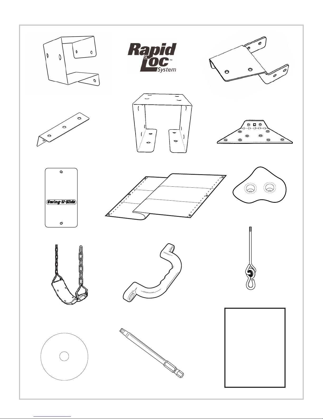
BLACK
R
(12) Shelf-Loc
(8) Step Brackets
Note: (4 Left, 4 Right)
(1) Name Plate
(12) Wrap-Loc
(1) Multicolor Tarp
(2) Split Beam bracket
(2) EZ Frame Brackets
(4) Climbing Rocks
with Hardware
(2) Swing Seats
weight limit: 115 lbs.
(1) Instructional DVD
(4) Safety Handles
orx® Bit
(1) T30
T
5
(4) Swing Hangers
Kodiak
Plan
(1) Plan
Page 6
PROJECT 513
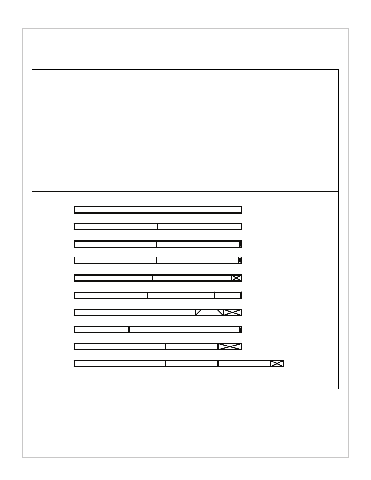
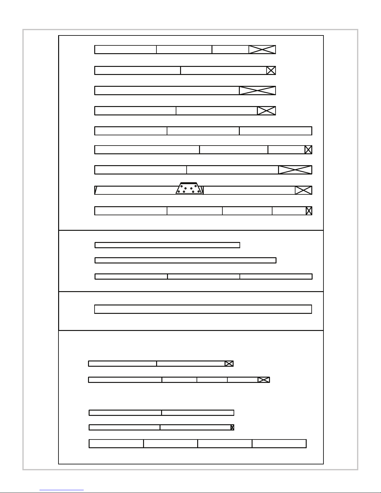
(2) 2'' x 4'' x 96''
48'' 48''
(2) 2'' x 4'' x 96''
47'' 47''
(2) 2'' x 4'' x 96''
96''
(1) 2'' x 4'' x 96''
47'' 48''
(1) 2'' x 4'' x 96''
45'' 45''
(2) 2'' x 4'' x 96''
42'' 38-1/2'' 14-3/4''
(2) 2'' x 4'' x 96''
69-1/2'' 16''
(2) 2'' x 4'' x 96''
52-1/2'' 30''
(1) 2'' x 4'' x 120''
52-1/2'' 30'' 30''
(16)-2'' x 4'' x 96''
(1)-2'' x 4'' x 120''
(17)-5/4'' x 6'' x 120''
(14)-5/4'' x 6'' x 144''
(
6)-4'' x 4'' x 96''
(4)-4'' x 4'' x 120''
(1)-4'' x 4'' x 144''
(1)-4'' x 6'' x 144''
(1)-2'' x 4'' x 96''
(2)-2'' x 4'' x 120''
O
PTIONAL LADDER BOARD LIST
(2)-2'' x 4'' x 96''
OPTIONAL ROCK WALL
(2)-5/4'' x 6'' x 144''
OR
(2)-2'' x 6'' x 144''
(2) 2'' x 4'' x 96''
31-1/2'' 31-1/2'' 31-1/2''
Two 45˚ Angle Cuts
PROJECT 513 CUTTING LIST
6
Page 7
(
2) 5/4'' x 6'' x 120''
9
6''
(7) 5/4'' x 6'' x 144''
48'' 48'' 48''
(1) 5/4'' x 6'' x 144''
48''
(2) 5/4'' x 6'' x 144''
69-1/2'' 45-1/2'' 24-1/2''
(
5) 5/4'' x 6'' x 120''
5
7''57''
(
3) 5/4'' x 6'' x 144''
6
1'' 61''
(1) 5/4'' x 6'' x 144''
72'' 61''
(8) 5/4'' x 6'' x 120''
54'' 54''
33'' 22-1/2''36-3/4''
(2) 5/4'' x 6'' x 120''
4
1'' 36-3/4''
(
2) 2'' x 4'' x 96''
6
9-1/2'' 16''
(
2) 2'' x 4'' x 96''
52-1/2'' 30''
(1) 2'' x 4'' x 120''
52-1/2'' 30'' 30''
(6) 4'' x 4'' x 96''
96''
(4) 4'' x 4'' x 120''
120''
(1) 4'' x 4'' x 144''
48'' 48'' 48''
(1) 4'' x 6'' x 144'' or (2) 2'' x 6'' x 144''
144''
(1) 2'' x 4'' x 96''
47''
(2) 2'' x 4'' x 120''
48''
OPTIONAL LADDER
23-1/4'' 20-1/4'' 20-1/4''
(1) 2'' x 4'' x 96''
47'' 47''
(1) 2'' x 4'' x 96''
48'' 48''
(2) 5/4'' x 6'' x 144''
36''36''36''36''
OPTIONAL ROCKWALL
2
4-1/2''
(
2) 2'' x 4'' x 96''
31-1/2'' 31-1/2'' 31-1/2''
47''
Two 45˚ Angle Cuts
PROJECT 513
7
Page 8

PROJECT 513
How to select the correct fastener
Use these 3 pictorial guides to help select the correct fastener(s) for the
lumber attachment you are making. Each diagram will highlight the correct
number of fasteners to use, and where to attach them.
5/4'' x 6'' to 4'' x 4''
(4) 2-1/2'' screws
Apply the 2-1/2" screws to secure the 5/4" boards
to the 4'' x 4'' uprights as shown.
Base of unit
(1) 2'' lag screw
After attaching the 2 1/2" screws, apply the center
(1) 2" lag screw as shown for additional support.
2'' x 4'' to 4'' x 4''
(3) 2-1/2'' screws
Apply 2 1/2" screws to the 2" x 4" boards
when attaching to 4"x 4" uprights.
5/4'' x 6'' to 2'' x 4''
(2) 2'' screws
Use 2" screws when mounting 5/4"
boards to 2" x 4" boards.
8
Page 9

PROJECT 513
Understanding how the Bracket System Works
helf-Loc Bracket
S
rap-Loc
W
1
Example of a Shelf-Loc bracket connection.
2
3
WRONG!
brackets NOT
interlocked!
CORRECT!
Brackets
''clipped''
4
Introduction to the Bracket system
1. ALWAYS Use 2'' lag screws on all brackets.
2. Brackets ''clip'' to each other. NEVER position
in a non-interlocking position.
Example of a Shelf-Loc bracket connection.
Look for ''TOP'' stamp on
bracket for correct orientation.
Shelf-Loc
9
TOP
GAP
(Hole locations close to bottom)
Brackets Clip Together
Top of bracket
Wrap-Loc
Bottom of bracket
Page 10

PROJECT 513
Use a 2’’ lag screw
to hold bracket in
place for later use.
L
ook for ‘’TOP’’
s
tamp on brackets
while installing.
TOP
GAP
on
th
is
sid
e
Fig.1
4'' x 4'' x 96''
Frame 1 Construction
(2)
2'' lag screws
per bracket
A. Frame 1 Construction
1. Measure, assemble and position
brackets on 4'' x 4'' as shown in
(Fig.1).
86''
47''
47''
Frame 1
Note: Secure Shelf Lock with (2) Lag
Screws only
at this time.
2'' Lag screw
10
Page 11
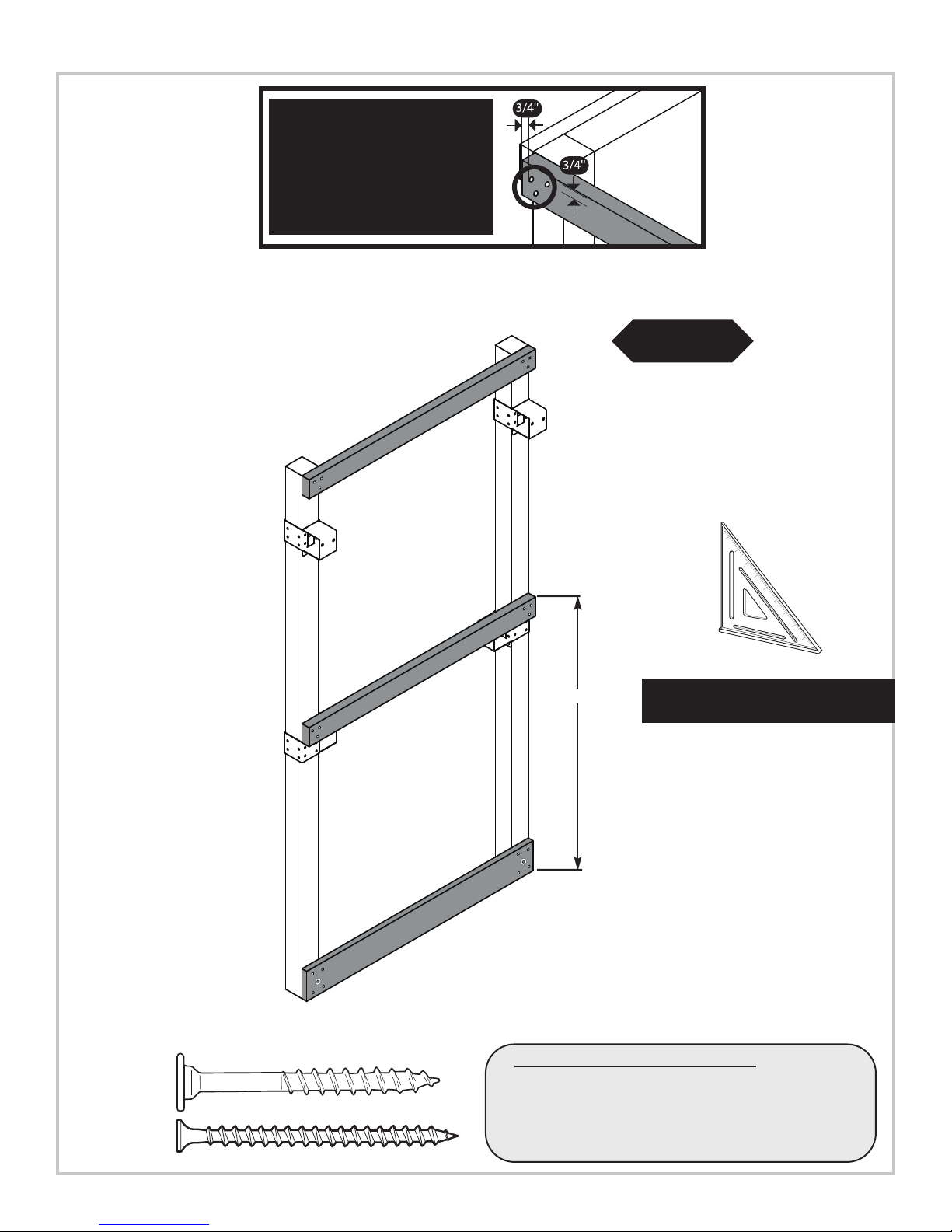
•WARNING•
Avoid splitting your
lumber by offsetting
your screws at least
3/4’’ from edge.
Frame 1 Construction
2-1/2'' screws
2'' x 4'' x 48''
PROJECT 513
(3)
Fig.1a
2'' Lag screw
2-1/2'' screw
2'' x 4'' x 48''
5/4'' x 6'' x 48''
(1) 2'' lag screw
(4) 2-1/2'' screws
Frame 1
50-1/2''
Double check to make
sure structure is square
A. Frame 1 Construction cont.
2. Attach 2'' x 4'' boar
shown in
(Fig. 1a)
ds and lower 5/4'' boar
d as
11
Page 12

PROJECT 513
Use a 2’’ lag screw
to hold bracket in
place for later use.
Look for ‘’TOP’’
stamp on brackets
while installing.
TOP
GAP
on
th
is
sid
e
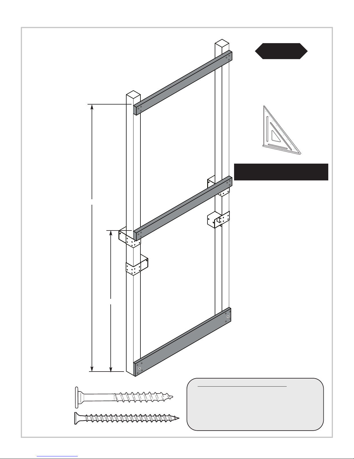
Frame 2 Construction
Fig.2
4'' x 4'' x 120''
(2)
2'' lag screws
per bracket
59''
47''
Frame 2
47''
59''
2'' Lag screw
12
B. Frame 2 Constr
uction
1. Measure assemble and position brackets on
4'' x 4'' as shown in (Fig.2).
Note: Secure Shelf Lock with (2) Lag
Screws only at this time.
Page 13

PROJECT 513
117''
Frame 2 Construction
(3)
2
-1/2'' screws
1-1/2''
'' x 4'' x 45''
2
'' x 4'' x 45''
2
Fig.2a
Double check to make
sure structure is square
96''
54-1/2''
2-1/2'' screw
5/4'' x 6'' x 48''
5/4'' x 6'' x 48''
Frame 2
(1) 2'' lag screw
(4) 2-1/2'' screws
B. Frame 2 Constr
2. Attach upper 2'' x 4'' and lower 5/4''
boards as shown in (Fig. 2a)
uction cont.
13
Page 14

PROJECT 513
Use a 2’’ lag screw
to hold bracket in
place for later use.
L
ook for ‘’TOP’’
stamp on brackets
while installing.
TOP
GAP
on
th
is
side
Frame 3 Construction
Fig.3
4'' x 4'' x 120''
(2)
2'' lag screws
per bracket
59''
47''
2'' Lag screw
Frame 3
59''
47''
C. Frame 3 Constr
uction
1. Measure assemble and position brackets on
4'' x 4'' as shown in (Fig.3).
Note: Secur
e Shelf Lock with
(2) Lag Scr
ews
only at this time.
14
Page 15
Frame 3 Construction
'' x 4'' x 48''
2
(3)
2
-1/2'' screws
PROJECT 513
Fig.3a
Double check to make
sure structure is square
117''
62-1/2''
2'' x 4'' x 48''
5/4'' x 6'' x 48''
Frame 3
(1) 2'' lag screw
(4) 2-1/2'' screws
2'' Lag screw
2-1/2'' screw
C. Frame 3 Construction cont.
2. Attach upper 2'' x 4'' and lower 5/4'' boards
as shown in
(Fig. 3a)
15
Page 16
PROJECT 513
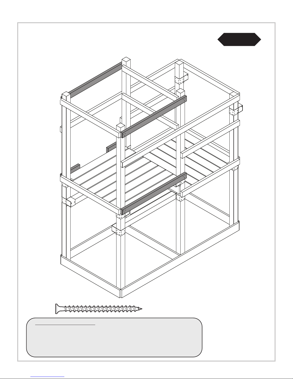
Fig.4
78''
2'' x 4''
x 47''
5/4'' x 6'' x 96''
2'' x 4'' x 47''
(3)
2-1/2'' screws
D. Frame Construction
’ and 5/4'' boar
1.Install 2’
’ x 4’
5/4'' x 6'' x 96''
ds as shown above.
(1) 2'' lag screw
(4) 2-1/2'' screws
2'' Lag screw
2-1/2'' screw
Frame One
16
Page 17
Double check to make
sure structure is square
2-1/2'' screws
PROJECT 513
Fig.4a
(
3)
(1) 2'' lag screw
(4) 2-1/2'' screws
D. Frame Construction cont.
1. Attach Frame Two as shown above.
Frame Two
47''
Frame One
2'' Lag screw
2-1/2'' screw
17
Page 18
PROJECT 513
Tip: Flex brackets to make installation of
4'' x 4'' easier
Fig. 5a
Approx. 1/4''
Fig.5
4'' x 4'' x 96''
F. Install 4x4s
1. Work (2) 4'' x 4'' into brackets as
shown in
2. Secure brackets (Fig. 5b).
(Fig. 5), (Fig 5a).
2'' Lag screw
x 4
4'' x 4'' x 96''
(4)
2'' Lag Screws
Fig.5b
18
Page 19

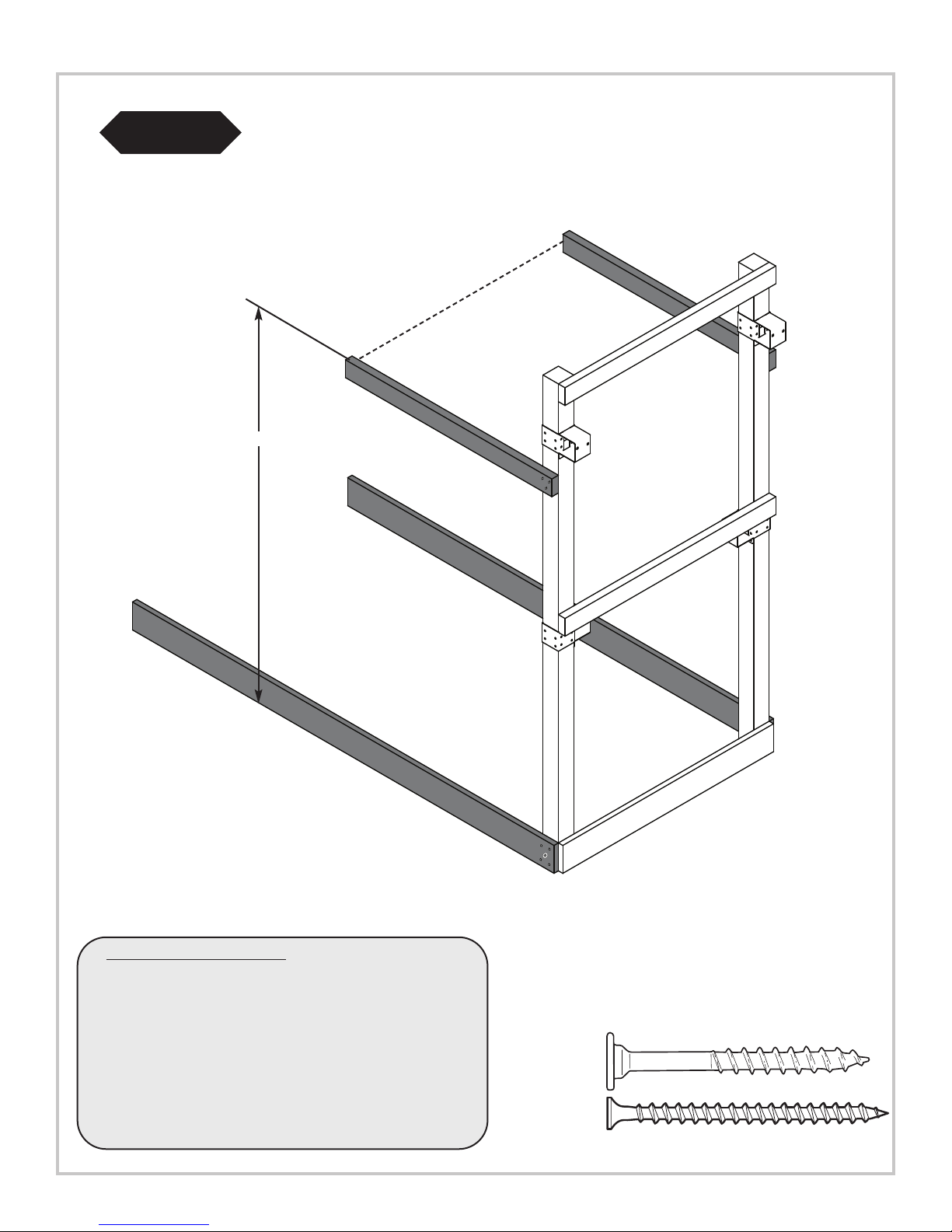
(
4) 2'' Lag Screws
PROJECT 513
Fig.6
Double check to make
sure structure is square
(4) 2-1/2'' screws
(1) 2'' lag screw
(Per joint)
Frame 3
Frame 2
Frame 1
F. Attach Frame 3.
1. Attach and secure Frame 3 to rest of unit as
shown above.
2'' Lag screw
2-1/2'' screw
19
Page 20
PROJECT 513
Fig.7
2-1/2'' screw
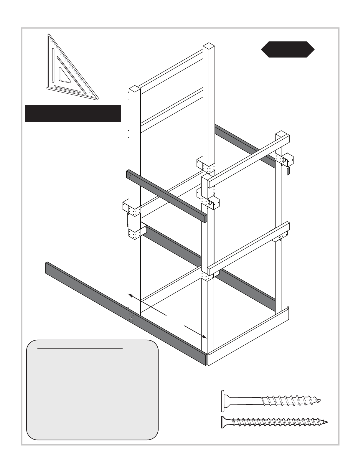
G. Install Deck Boards
5/4'' x 6'' x 41''
2
-1/2'' screws
(6) 5/4'' x 6'' x 48''
5/4'' x 6'' x 41''
(2)
1. Install 5/4'' deck boards to structure as shown (Fig. 7).
2. Use two 2-1/2'' screws at each end of deck boards.
Note: On End Boards, avoid screwing into Shelf Brackets by
placing scr
ews behind Shelf Bracket location.
20
Page 21
Bottom View
Fig.8b
15''
PROJECT 513
Fig.8
(
2)
2
-1/2'' screws
p
er joint
Fig.8a
(16)
2-1/2'' screws
2'' x 4'' x 47''
2-1/2'' screw
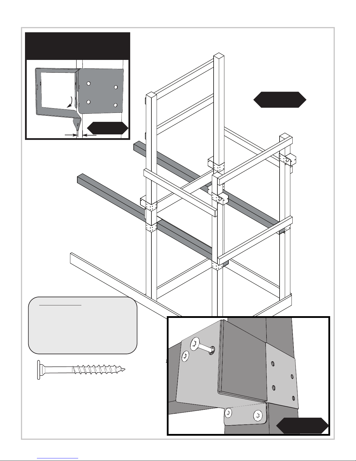
H. Lower Deck Support Board
ds as shown in (
1. Constr
uct suppor
2. Secure center of floor boards as shown in (Fig 8a)
3. Hold Deck
ed in place fr
secur
(Fig. 8b).
t boar
Fig. 8).
Support Board from below until
om above as shown in
21
Page 22

PROJECT 513
Fig.8c
2'' x 4'' x 47''
2'' x 4'' x 47''
(3)
2-1/2'' screws
I. Install Lower Rail Boar
d
1. Install lower 2'' x 4'' rail board as shown in (Fig 8c).
Flush with the sides of 4'' x 4'' deck suppor
ts.
2-1/2'' screw
(3)
2-1/2'' screws
22
Page 23

(3)
2-1/2'' screws
2
'' x 4'' x 96''
2
''
x 4'' x 96''
PROJECT 513
Fig.9
(3)
2
-1/2'' screws
K. Install Shelf-Loc brackets
1. Install 2x4 boards as shown in (Fig.9).
2-1/2'' screw
23
Page 24

PROJECT 513
Tip: Flex brackets to make installation of
4'' x 4'' easier
Approx. 1/4''
Fig.10
4'' x 4'' x 48''
Fig.10a
4'' x 4'' x 48''
2'' Lag screw
Fig.10b
x 4
K. Install 4x4s cont.
1. Work (2) 4'' x 4'' into brackets as shown in (Fig. 10a), (Fig 10).
2. Secure brackets (Fig. 10b).
24
Page 25

PROJECT 513
Fig.11
(2)
2
-1/2'' Deck Screws
(2 per joint)
MAKE
BOARDS
FLUSH WITH
4'' x 4''
SUPPORT
(1) 5/4'' x 6'' x 45-1/2''
(6) 5/4'' x 6'' x 48''
(1) 5/4'' x 6'' x 45-1/2''
2-1/2'' screw
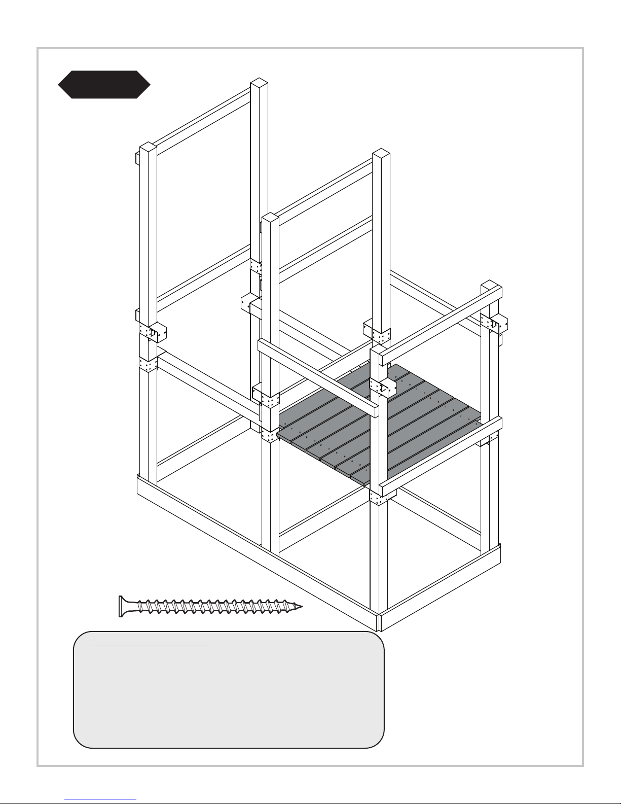
L. Install Deck Boards
1. Install 5/4'' deck boards to structure as shown (Fig. 11).
2. Use two 2-1/2'' scr
bracket blocks scr
on either side.
ews at each end of deck boar
ew path, center boar
ds. Wher
d and place one scr
25
e shelf
ew
Page 26

PROJECT 513
Fig.12
17-1/4''
Fig.12a
Fig.12b
(16)
2-1/2'' screws
2'' x 4'' x 48''
2-1/2'' screw
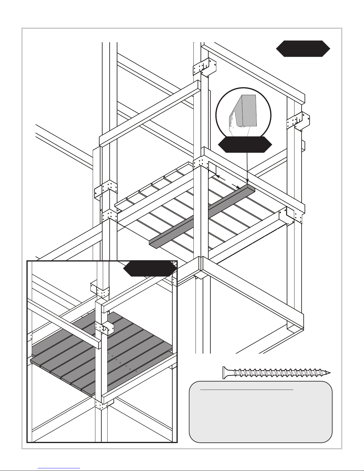
M. Install Upper Rail Boards
1. Install under deck suppor
Flush with the edges of 5/4’’ x 6’’ deck supports.
2. Hold Deck Support Board from below until secured in
place from above as shown in (Fig. 12a) and
(Fig. 12b).
t as shown in
(Fig 12).
26
Page 27
(
3)
2
-1/2'' Screws
(
5)
2-1/2'' Screws
p
er board
PROJECT 513
Fig.13
2'' x 4'' x 52-1/2''
2'' x 4'' x 52-1/2''
(2) 2'' x 4'' x 14-3/4''
2-1/2'' Screws
2-1/2'' screw
N. Install supports cont.
1. Install 2'' x 4'' as shown in (Fig 13)
2'' x 4'' x 52-1/2''
(3)
27
Page 28

PROJECT 513
Tip: Flex brackets to make installation of
4'' x 4'' easier
Fig. 15
A
pprox. 1/4''
Fig.14
O. Install accessory 4x4
1. Work (1) 4'' x 4'' into brackets as shown in
(Fig. 14), (Fig 15).
2. Secur
e brackets
(Fig. 16).
4'' x 4'' x 48''
(
4)
2
'' Lag Screws
Fig.16
2'' Lag screw
28
x 4
Page 29

Optional Laminated Beam
PROJECT 513
Fig. 17
Fig. 17a
NOTE:
Lay the lumber on a flat surface
before beginning laminated beam assembly.
NOTE:
Attach one end of the beam with three
2-1/2'' screws. Secure boards and attach the
other end with three 2-1/2'' screws. This will
insure that your boards will stay aligned
throughout the remainder of the beam assembly.
P. Laminated Beam Instructions
24"
Stagger screws to
insure a sturdy
bond between
boards
1. If 4" x 6" lumber is not available, you may
laminate two 2" x 6" x 144'' pieces of lumber
together to create the beam.
2. Lay the lumber on a flat sur
the edges.
lumber is the same length. If it is not, trim boar
3. From the end of each board, measure and place a
mark at 24" intervals
4. Assemble the beam by attaching each end
together using three 2-1/2'' screws
Note:
Stagger the screws as shown in (Fig. 17a) to
insure a sturdy bond. Repeat every 24" along the
e length of the beam.When beam is complete,
entir
measure, drill holes, and attach beam clamps and
nylon bushing swing hangers
NOTE: Make sure each piece of
face and align all of
d(s).
(Fig. 17).
(Fig. 17a).
29
Page 30

PROJECT 513
3-1/2''
Fig. 18
Q. Swing Beam Drill Locations
1. Use a 3/8'' drill bit to drill a 3/8’’ hole through
the beam at each location shown in (Fig. 18)
2. Install Swing Hangers onto swing beam at
locations shown.
Note: Swing Hangers must be installed on
same side dimensions were originally marked.
Drill 3/8''
Hole
TOP VIEW
3-1/2''
Swing Beam
30
Page 31

(4) 1-1/4'' screws
Swing Hanger
Use Screwdriver to aid in tightening
Bottom Beam Clamp
t-nut
Hammer
3/8'' hole
T-nut
PROJECT 513
Fig. 19
Q. Swing Beam Drill Locations
ap t-nut into 3/8’
1. T
2. Place a bottom beam clamp over the swing hanger as shown in (Fig. 19)
3. Insert the swing hanger into the beam and thread it into the T-nut until it is flush or near flush with the top of the
-nut. A screwdriver may be used to twist the hanger
T
4. Use (4) 1-1/4'' screws to secure beam clamp.
5. Check hanger to ensure it does not spin.
6. Repeat for both swing hangers.
’ hole as shown in
(Fig. 19)
(Fig. 19). Orient swing hanger as shown in (Fig 19).
31
Page 32
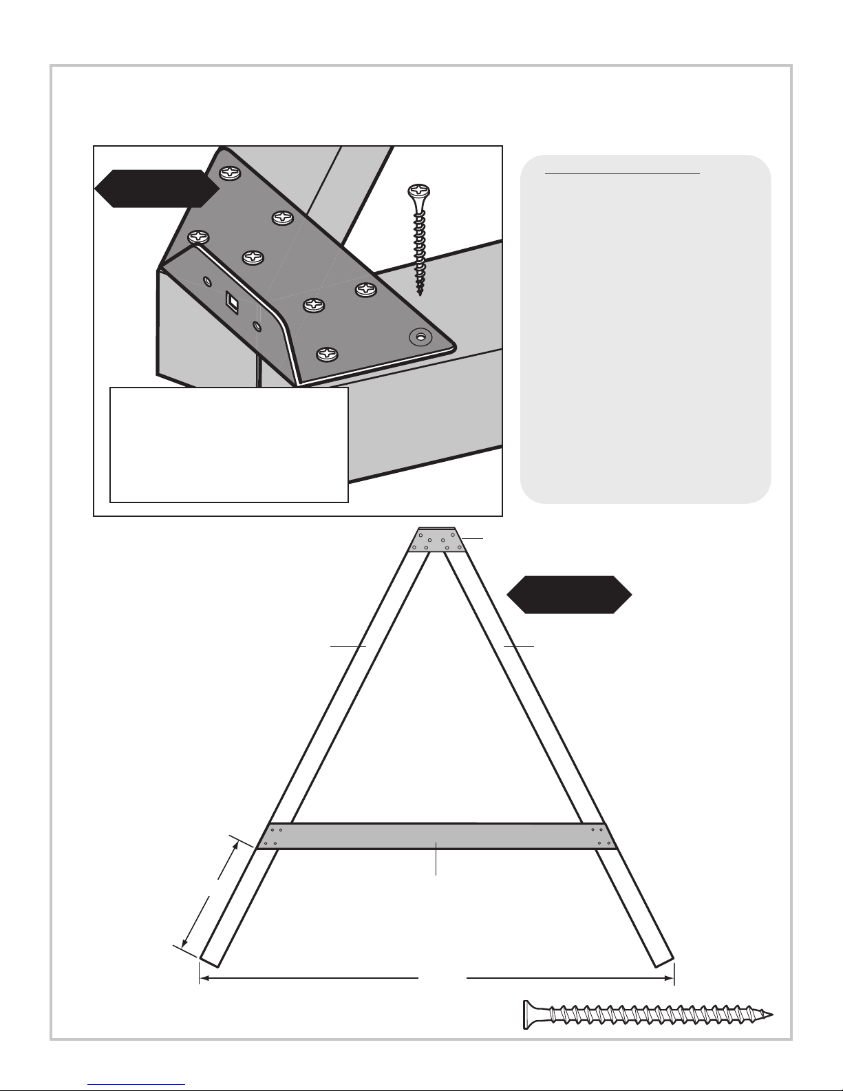
PROJECT 513
Fig. 20
Align the edges of the 4" x 4" legs
with the edges of EZ Frame Bracket
(8) 2-1/2ʼʼ Screws
R. A-Frame Assembly
1. layout 4'' x 4’’s as shown
in (Fig. 20)
2. Align EZ Frame Bracket with face of
4'' x 4''s.
3. Secure EZ Frame Bracket with (8)
2-1/2'' screws to 4'' x 4''s making
sure they are flush with each other.
4. Secure 5/4'' x 6'' to 4'' x 4''s as
shown in (Fig. 21)
Flip over and add 2nd bracket.
5.
Repeat steps 2 and 3.
EZ Frame
Bracket
2-1/2'' screws
24-1/2"
4" x 4" x 96''
(4)
5/4" x 6" x 72"
94-1/2"
Fig. 21
4" x 4" x 96''
(4)
2-1/2'' screws
2-1/2'' screw
32
Page 33
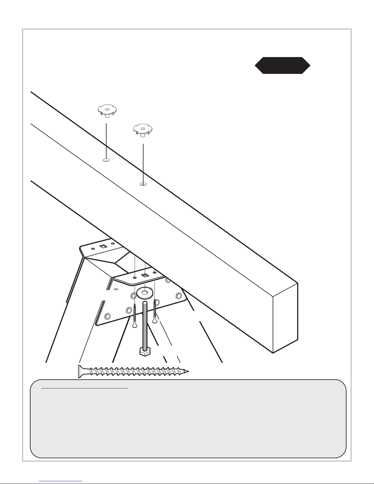
Can
tile
ver
be
am
T-nut
PROJECT 513
Fig. 22
Washer
2-1/2'' screws
5-1/2ʼʼ Hex Bolt
2-1/2'' screw
S. A-Frame Assembly cont.
1. 1. Tap T-nut into 3/8’’ hole as shown in (Fig. 22)
Note: If using Laminated Swing Beam, make sure T-nut teeth do not fall between seams of 2'' x 6''s.
2. Attach A-Frame beam to Swing Beam using (2) 5-1/2’’ hex bolts and 4 screws.
3. Tighten hex bolt to flush with top of T-nut. Repeat on other bracket.
33
Page 34
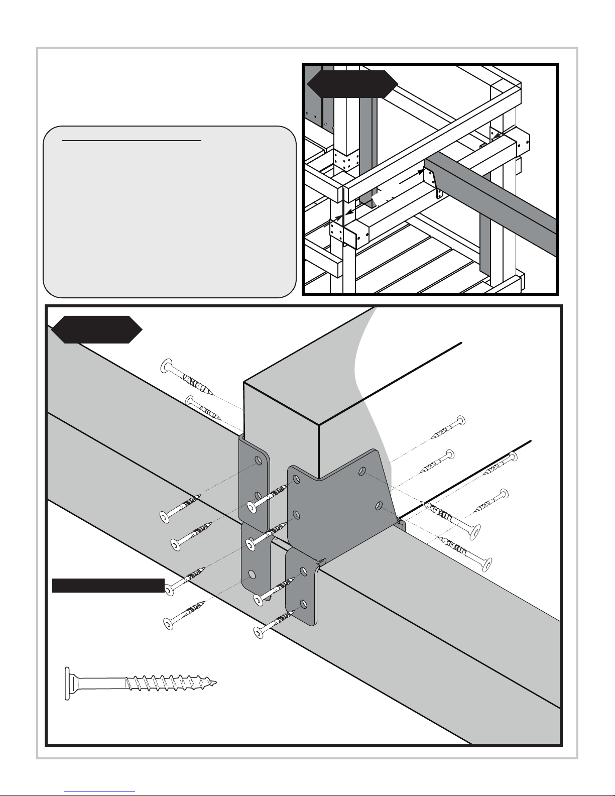
PROJECT 513
A-Frame Assembly cont.
T.
1. Position Split-Brackets on 4'' x 4'' x 48'' (Fig 23).
2. With the help of others, lift A-Frame and
Swing Beam Assembly and center onto unit as
shown in (Fig. 23)
3. Secure as shown in (Fig 24).
Fig. 24
Fig. 23
22-1/4''
Swing Beam
View from Deck
Swing Beam
2'' Lag screw
x 8 (each bracket)
34
Page 35
(
2)
2-1/2'' Deck
Screws
per joint
PROJECT 513
Fig.25
5/4'' x 6'' x 57''
5/4'' x 6'' x 57''
5/4'' x 6'' x24-1/2''
5/4'' x 6'' x24-1/2''
5/4'' x 6'' x24-1/2''
5/4'' x 6'' x24-1/2''
5/4'' x 6'' x 57''
5/4'' x 6'' x 57''
2'' Deck Screws
(2 per joint)
2
'' Deck Screws
(2 per joint)
1-1/2ʼʼ Gap
(
2) 2'' x 4’’ x 30''
1
-1/2ʼʼ Gap
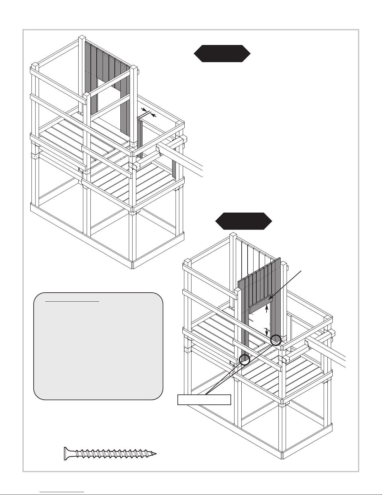
V. Barrier Boards
1. Install 2x4 and 5/4'' barrier boards
evenly spaced in the opening.
Make Bottom of Boards Flush
ith Bottom of Deck
W
Support
Fig.25a
x 69-1/2''
’
2'' x 4’’ x 31-1/2''
2'' x 4’’ x 31-1/2''
2'' x 4’
33-1/2ʼʼ
Bottom of
5/4'' x 6’’ x 69-1/2''
To Deck
2'' x 4’’ x 31-1/2''
Board
(1) 5/4'' x 6’’ x 22-1/2''
’ x 31-1/2''
2'' x 4’’ x 69-1/2''
2'' x 4’’ x 31-1/2''
2'' x 4’’ x 31-1/2''
2'' x 4’
x 69-1/2''
’
5/4'' x 6’
2'' Deck Screws
(2 per joint)
2'' screw
35
Page 36

PROJECT 513
5/4'' x 6'' x 61''
5/4'' x 6'' x 61''
5/4'' x 6'' x 61''
5/4'' x 6'' x 61''
5/4'' x 6'' x 61''
5/4'' x 6'' x 61''
5/4'' x 6'' x 61''
2
'' Deck Screws
(
2 per joint)
5/4'' x 6'' x 48''
Fig.26
5/4'' x 6'' x 48''
5/4'' x 6'' x 48''
2
'' Deck Screws
(
2 per joint)
5/4'' x 6'' x 48''
5/4'' x 6'' x 48''
V. Barrier Boards cont.
1. Install 5/4'' barrier boards evenly
spaced in the opening.
2'' Deck Screws
(2 per joint)
Fig.26a
5/4'' x 6'' x 57''
5/4'' x 6'' x 57''
5/4'' x 6'' x 57''
5/4'' x 6'' x 36-3/4''
5/4'' x 6'' x 57''
5/4'' x 6'' x 36-3/4''
5/4'' x 6'' x 57''
5/4'' x 6'' x 57''
2'' x 4’’ x 30''
1-1/2ʼʼ Gap
1-1/2ʼʼ Gap
2'' x 4’’ x 30''
2-1/2'' Deck Screws
(2 per joint on 2'' x 4''s)
2'' screw
36
Page 37

Fig.27
PROJECT 513
x2
2'' x 4'' x 38-1/2''
2'' x 4'' x 16''
2'' x 4'' x 42''
W. Roof Construction.
1. Constuct Wood Roof Frame as shown in
(Fig 27) and (Fig. 27a).
Fig.28
(3)
2-1/2'' Deck Screws
(per joint)
1
-1/2'' Overhang
Fig.27a
(4) 5/4'' x 6'' x 54''
48''
(
2)
2
-1/2'' Deck Screws
(
per joint)
1
-1/2'' Overhang
2-1/2'' screw
(3)
2-1/2'' Deck Screws
(per joint)
W. Roof Constr
uction.
2. Attach wood Roof as shown in (Fig 28)
37
Page 38

PROJECT 513
Fig.29
Fig.30
2-1/2'' Deck Screws
(
2 per joint)
(6) 5/4'' x 6'' x 54''
(6) 5/4'' x 6'' x 54''
2-1/2'' Deck Screws
(2 per joint)
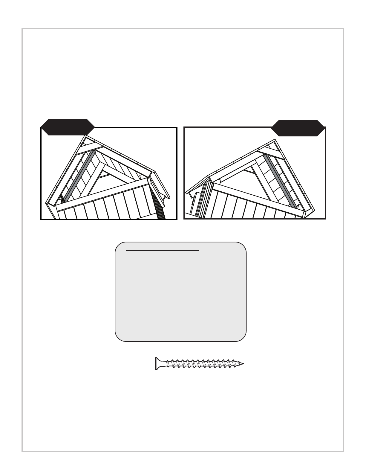
X Roof Constr
3. Install 5/4'' x 6''s as shown in (Fig 29) and
(Fig. 30).
uction cont.
2-1/2'' screw
38
Page 39
PROJECT 513
Fig.30a
2'' Deck Screws
(
2 per joint)
(1) 5/4'' x 6'' x 33''
(1) 5/4'' x 6'' x 36-3/4''
X Support Boards cont.
1. Install 5/4'' x 6'' Roof Supports as shown in
(Fig 30a) and (Fig 30b).
Fig.30b
2
'' Deck Screws
(2 per joint)
2'' screw
39
Page 40
PROJECT 513
(Left Side)
2'' x 4'' x 48''
(Right Side)
(Front)
2'' x 4'' x 48''
43-5/8’’
43-5/8’’
42-1/8’’
29-1/2’’
17’’
4-3/8’’
2-3/4’’
15-1/4’’
27-7/8’’
40-3/8’’
40-3/8’’
27-7/8’’
15-1/4’’
2-3/4’’
4-3/8’’
17’’
29-1/2’’
42-1/8’’
(2) 2-1/2’’ Screws
(2) 2-1/2’’ Screws
(2) 2-1/2’’ Screws
(2) 2-1/2’’ Screws
(2) 2-1/2’’ Screws
(2) 2-1/2’’ Screws
(2) 2-1/2’’ Screws
(2) 2-1/2’’ Screws
2'' x 4'' x 23-1/4''
2'' x 4'' x 23-1/4''2'' x 4'' x 23-1/4''
2'' x 4'' x 20-1/4''
2'' x 4'' x 20-1/4''
2'' x 4'' x 20-1/4''
2'' x 4'' x 20-1/4''
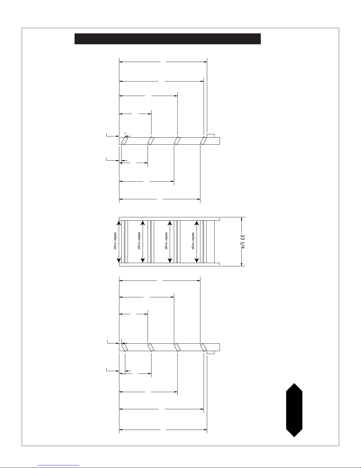
SIDE OPENING OPTION 1
Fig. 31
40
Page 41
• BOTTOM OF LADDER RAIL •
To p
Co
rne
r o
f 2
''
x 4
''
Bot
tom
Co
rner
of 2
''
x
4''
2- 3/
4''
Fro
m Bott
om
(
6)
1-1/4''
screws
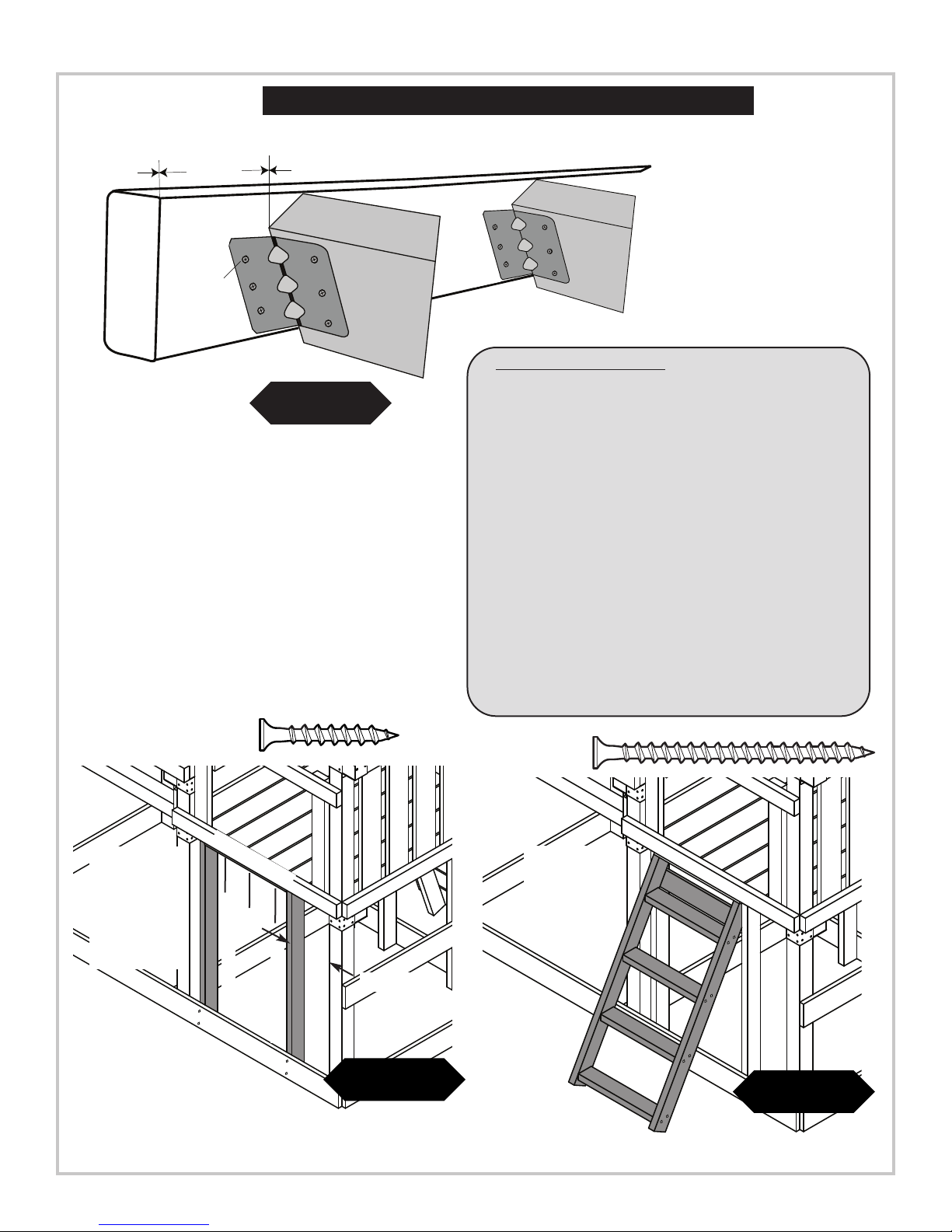
EXAMPLE OF LADDER RUNG INSTALLATI ON
STEP
BRAC
KET
2-1/2''
PROJECT 513
SIDE OPENING OPTION 1
O. Ladder Assembly.
(6) 1-1/4'' screws
(2)
2-1/2'' screws
each side
Fig. 32
2'' x 4'' x 23-1/4''
1. On ladder rails, mark all measurement locations for
each side with a pencil. Draw an angle line
connecting measurements for each ladder rung
alignment.
(Fig. 31)
2. Align top of step bracket with line and screw in
place. Install a ladder rung at each of the four
locations. (Fig. 31) and (Fig. 32). Repeat on other
ladder rail.
3. Attach 2'' x 4'' x 23-1/4'' to siderails using
(2) 2-1/2'' screws per side.
4. Secure ladder to unit. (Fig. 33), and (Fig. 34)
Note: The top step should be 11" below the deck
and all steps should be level.
5. Screw (2) 2-1/2" screws into the ends of each ladder
rung through the left and right side rails. (Fig. 34)
2-1/2'' screw
(3)
2-1/2'' screws
each side
(3)
2-1/2'' screws
underneath
2'' x 4'' x 47''
(2)
2-1/2'' screws
each side
2'' x 4'' x 47''
10-3/4''
Fig. 33
(2)
2-1/2'' screws
per joint
Fig. 34
41
Page 42

PROJECT 513
Fig. 35
19''
5/4'' x 6'' x 48''
2-1/2'' screw
Z1. Install Pr
(9)
2-1/2'' Deck Screws
(3 Per joint)
otective Barrier Board
1. Secure protective 5/4'' barrier board as shown in (Fig 35).
42
Page 43

THIS PRODUCT IS
INTENDED FOR USE
BY CHILDREN FROM
AGES 2-10 YEARS
For Home / Residential
Use ONLY
1212 Barberry Drive
Janesville, WI 53545
1-800-888-1232
www
B
LACK
R
washer
1 - 3/4
Panhead
screw
INST
PROJECT 513
Fig. 36
Fig. 37
11"
Deck Surface
ALL PLAY HANDLES
HERE
Slide/Safety Handle
Installation.
1. Mount safety handles in the ladder
opening approximately 11'' above the
deck sur
face
(Fig. 36).
2. Install Slide as shown in (Fig. 37)
Important:
Do not use hardware provided
with slide. Use Truss head screws
included with Kit.
russ Screw
1'' T
Use truss head screws to
to secure slide to deck.
Secure your product ID tag onto easy
to read location of any 4'' x 4''
using (2) 2'' screws
43
Page 44

PROJECT 513
Fig. 38
Anchor-It
metal strap
(Sold Seperately)
Flat Washer
1-1/2"
lag bolt
Anchor-It
stake
S. Anchor-It Installation (optional).
IInnssttrruuccttiioonnss ffoorr AAnncchhoorriinngg SSwwiinngg••NN••SSlliiddee AAccttiivviittyy CCeenntteerrss
1. Determine the final location of your activity center.
2. Place the Anchor
on swing sets) and twist the auger
3. Place the metal strap through the loop of the Anchor-It stake and secure it to the unit with a lag screw and washer
as illustrated to the right. Note: Attach the strap to the unit with as little play as possible using whatever holes in the
strap that work best.
-It stakes adjacent to the base and near the cor
-style stakes into the ground until only the loop is exposed.
ners of your activity center (at the bottom of the legs
44
Page 45

SIDE OPENING OPTION 2
Fig. 39
PROJECT 513
Fig. 40
9-1/2''
2'' x 4'' x 47''
2-1/2'' screw
2'' x 4'' x 47''
2-1/2'' Deck Screws
(2 Per joint)
9-1/2''
8) 5/4'' x 6'' x 36'
(
2'' x 4'' x 48''
6''
(
2)
2-1/2'' screws
(Per joint)
'
'' x 4'' x 48''
2
6''
Fig. 40a
2-1/2'' Deck Screws
(2 Per joint)
NNOOTTEE::
4' Climbing Rock Wall will require
MMiinn.. 88 CClliimmbbiinngg RRoocckks
s
(2) Bags of NE 4543S Climbing Rocks.
Climbing Wall Lumber Cut List.
(1) 2x4x96 ------ (2) 2x4x47
(1) 2x4x96 ------ (2) 2x4x48
(2) 5/4x6x144 - (4) 5/4x6x36
1. Assemble and install Climbing Wall Frame as shown
in (Fig. 39), (Fig. 40).
2. Attach (8) 5/4'' x6'' boards to (2) 2'' x 4'' boards
and install on unit as shown in (Fig. 40a).
3. Secure Rock Wall to unit using (3) 2-1/2'' screws
per side.
Note: Make sur
interfere with the mounting of the climbing
rocks.
e the 2'' x 4'' suppor
ts do not
45
Page 46

PROJECT 513
Fig. 41
2) 2'' Hex Head Bolts
(
Climbing Rock
Climbing Rock
2)"T" nuts
(
3/8" Holes
old (rock)
H
(1) Loc Washer per bolt
(1) Flat Washer per bolt
Climbing Rock Installation
1. Mark locations of Climbing Rocks on the Climbing Wall in a pattern that
will easily allow your child to climb to the deck. Make sure the bolt hole
locations are clear of wall supports before drilling.
2.Drill holes through the wall at the desired locations using a 3/8" drill bit.
Install Climbing Rocks as shown in
3. Make sure the Climbing Wall and Climbing Rock connections are secure
before allowing any children to play on the Climbing Wall.
(Fig. 41).
46
46
Page 47

PROJECT 513
47
Page 48

Questions???...
Call our Customer Service Department
at 1-800-888-1232
© PlayCore Inc. 2007 Printed In USA LA 5821
 Loading...