

Page 1
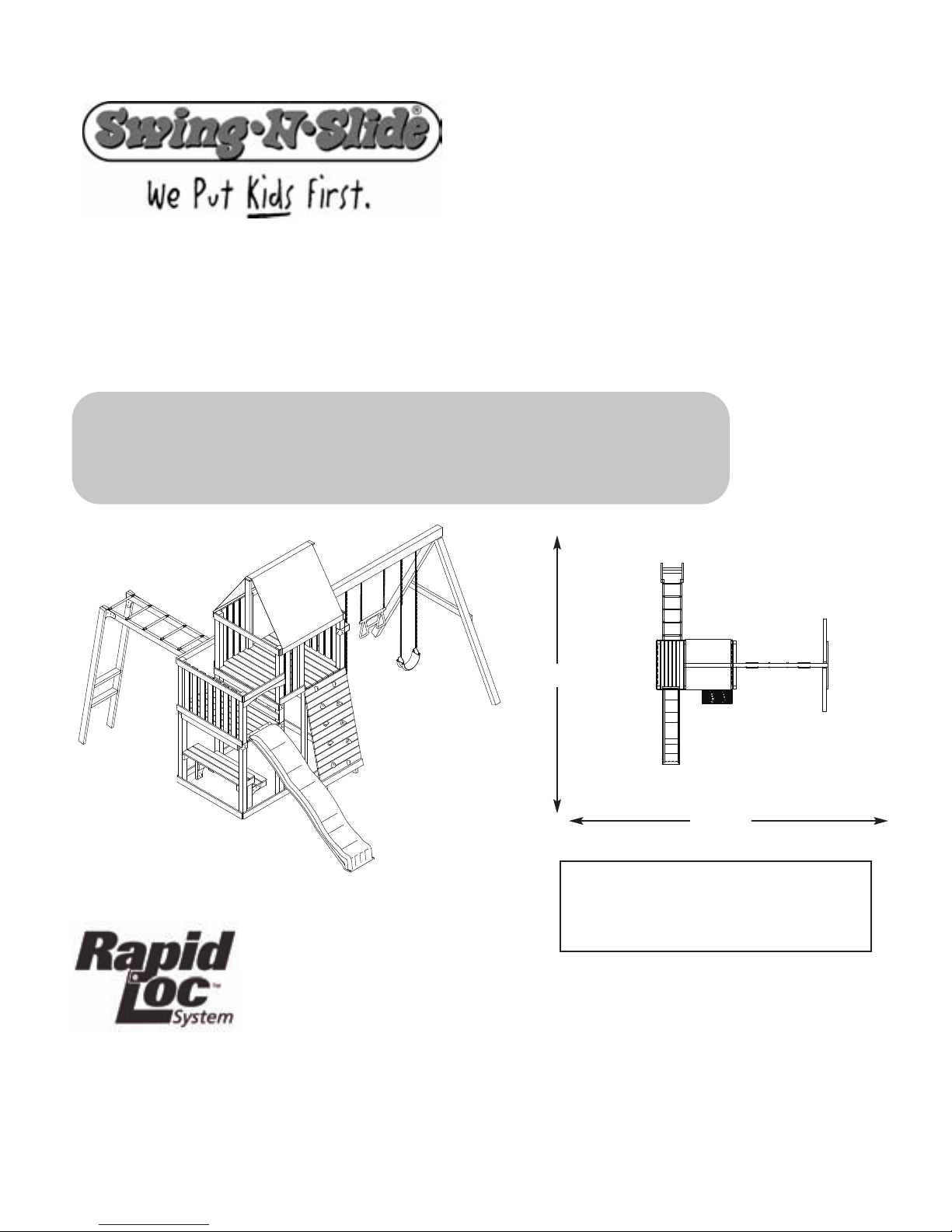
Chesapeake
check out http://www.swing-n-slide.com/planupdates.html
for updates to these instructions
For more information, visit this link:
http://www.swing-n-slide.com
PB 8243
TM
ASSEMBLY INSTRUCTIONS
Swing•N•Slide • 1212 Barberry Drive • Janesville, Wisconsin 53545
Visit our web site at: www.swing-n-slide.com or call us at 1-800-888-1232
28'-6''
26'-6''
No. of Children: Up to 12
26
Min. Use Zone:
Set Dim.
Est. BuildingTime: 5-10 hr.
14-1/2
-1/2' x
'W x
16-1/2
28-1/2'
'L x 11'H
Page 2

Safety Checklist for Swing-N-Slide Play Sets and Accessories
R
Observing the following statements and warnings reduces the likelihood of serious or fatal injury
Installation Safety – Have You:
Consulted the assembly instructions supplied with your particular model?
Noted this accessory is to be used only on Swing•N•Slide approved designs? (Do not alter its design or add/remove components.)
Made sure all hardware is tightened securely? (Supplied bolt covers must also be fastened securely.)
Using a hacksaw, cut off all protruding threaded ends of bolts and other fasteners and remove any sharp edges with
a metal file as needed?
Placed the equipment on level ground, not less than six feet (1.8 meters) from any structure or obstruction such as a fence, garage,
house, overhanging branches, laundry lines, or electrical wires?
Made sure home playground equipment is not installed over concrete, asphalt, packed earth or any other hard surface? (A fall onto
a hard surface can result in serious injury to the equipment user.)
Verified that suspended climbing ropes, chain,or cable are secured at both ends?
Consulted in assembly instructions of your particular model for minimum use zones?
Followed all anchoring and shock absorbing surfacing requirements on the back of this sheet as they apply?
Made sure not to allow children to use equipment until it is properly installed?
Operating Safety – Have You:
Determined that on-site adult supervision is provided for children of all ages?
Warned children the following before allowing them to use the equipment?
Not to walk close to, in front of, behind or between moving items.
Not to twist swing or any other accessory chains or ropes or loop them over the top support bar since this will reduce the
strength of chain or rope.
Not to swing empty seats or other accessories.
Be sure to sit in the center of the swing seat and other accessories with full weight on the seat.
Not to attach items to the playground equipment that are not specifically designed for use with the equipment such as but not
limited to, jump ropes, clotheslines, pet leashes, cables and chain. They may cause a strangulation hazard.
Not to use equipment in a manner other than intended.
Not to get off equipment while it is in motion.
Not to climb on the equipment when it is wet.
Determined that only one child per planned occupant seat should be allowed on this set at one time.
Determined children must be dressed appropriately for play. Avoid clothing with draw strings and loose fitting clothes which
could become entangled or snagged on equipment.
Determined that suspended climbing ropes, chain, or cable cannot be looped back upon itself.
Read and understood the following warning regarding the use of two and four passenger lawn swings?
Warning: Lawn Swings are designed for use by children over two years of age. Use by children under the age of two can result
in entrapment between the seats and back areas. Never place children in a rearward facing position or with legs between the
seat and backrest because the child’s body may pass through the opening causing entrapment of the child’s head.
Safety Maintenance – Have You Determined to:
Check all nuts and bolts twice monthly during the usage season for tightness and tighten as required? (It is
particularly important that this procedure be followed at the beginning of each season.)
To prevent the deterioration of materials, remove plastic swing seats and other plastic accessories and take indoors? (Do not
use when the temperature drops below 0° F.)
Oil all metallic moving parts monthly during usage period?
Check all hardware and equipment for sharp edges twice monthly during usage season? (Replace when
necessary. It is especially important to do this at the beginning of each new season.)
Check swing seats, chains, ropes and cables monthly during usage season for evidence of deterioration? Severe rusting or excessive
wear, especially near the top swing hanger or at the seat connection are evidence of chain deterioration. Cracks in the protective plastic
sleeve or seat itself are also signs of deterioration. If any of these conditions exist, call 1-800-888-1232 to order replacement accessories.
Sand rusted metal parts and repaint using non-lead based paint.
Disposal Instructions
When the equipment is taken out of service, it must be disassembled and disposed of in such a way that no unreasonable hazards
will exist at the time the set is discarded.
Important!
Save this instruction sheet in the event the manufacturer needs to be contacted.
Additional Safety Instructions for all Swing-N-Slide Playground Equipment.
2
Page 3

This product is intended for single family home/residential use only and not intended for use in any public setting.
According to ASTM requirements, all kits must be anchored to the ground and, if the unit has a climbing rope, the rope end must be anchored to the ground. If soil conditions
permit stakes to be pulled out easily, cementing into ground is necessary.
• To anchor the unit to the ground, Follow the instructions included in this plan for applying Anchor-It devices to your unit, or use 2" x 4" x 18" (45mm x 95mm x 457mm) pressuretreated stakes. Pound stakes into ground at least 12" (305mm) at all inside corners of the posts (including A-frame legs and climbing unit posts). Attach with four (4) 16D (3-1/2")
galvanized nails per stake into each 4" x 4" (95mm x 95mm) post.
• If the unit has a climbing rope, anchor the rope end.
• Once the unit is completely assembled and before children are allowed to play on it, proper shock-absorbing surfacing material must be installed. This may be accomplished by
using loose-fill materials at a sufficient depth. The Consumer Product Safety Commission “Handbook for Public Playground Safety” lists the following materials and required
depths that are sufficient for home/residential application. For fall height protection up to 9 ft. (2.742m) [recommended for Swing•N•Slide kits]:
Double Shredded Bark Mulch 9" (229mm)
These depths were derived from the CPSC Handbook. Swing•N•Slide has not done independent tests to determine these required depths.
When properly installed, shock absorbing material will completely cover the horizontal baseboards on climbing units. This protective surfacing must extend a minimum of 6 ft.
(1.828m) in all directions from the perimeter of the equipment or from the outermost edges of any component. For example, a slide extending beyond the platform must have
protective surfacing at least 6 ft. (1.828mm) out from both sides as well as the end. For swings, the protective surface must extend at least 14 ft. (6m)
front of the swing when the swing is in its rest position.
Placement in any public setting constitutes a misuse of this product.
ADDITIONAL REQUIRED SAFETY INSTALLATION INSTRUCTIONS
LOOSE FILL MATERIAL REQUIRED (UNCOMPRESSED) DEPTH1in. (mm)
Wood Mulch 9" (229mm)
Uniform Wood Chips 12" (305mm)
Fine Sand 12" (305mm)
Fine Gravel 12" (305mm)
IMPORTANT!
out from both the back and
NOTES:
3
Page 4
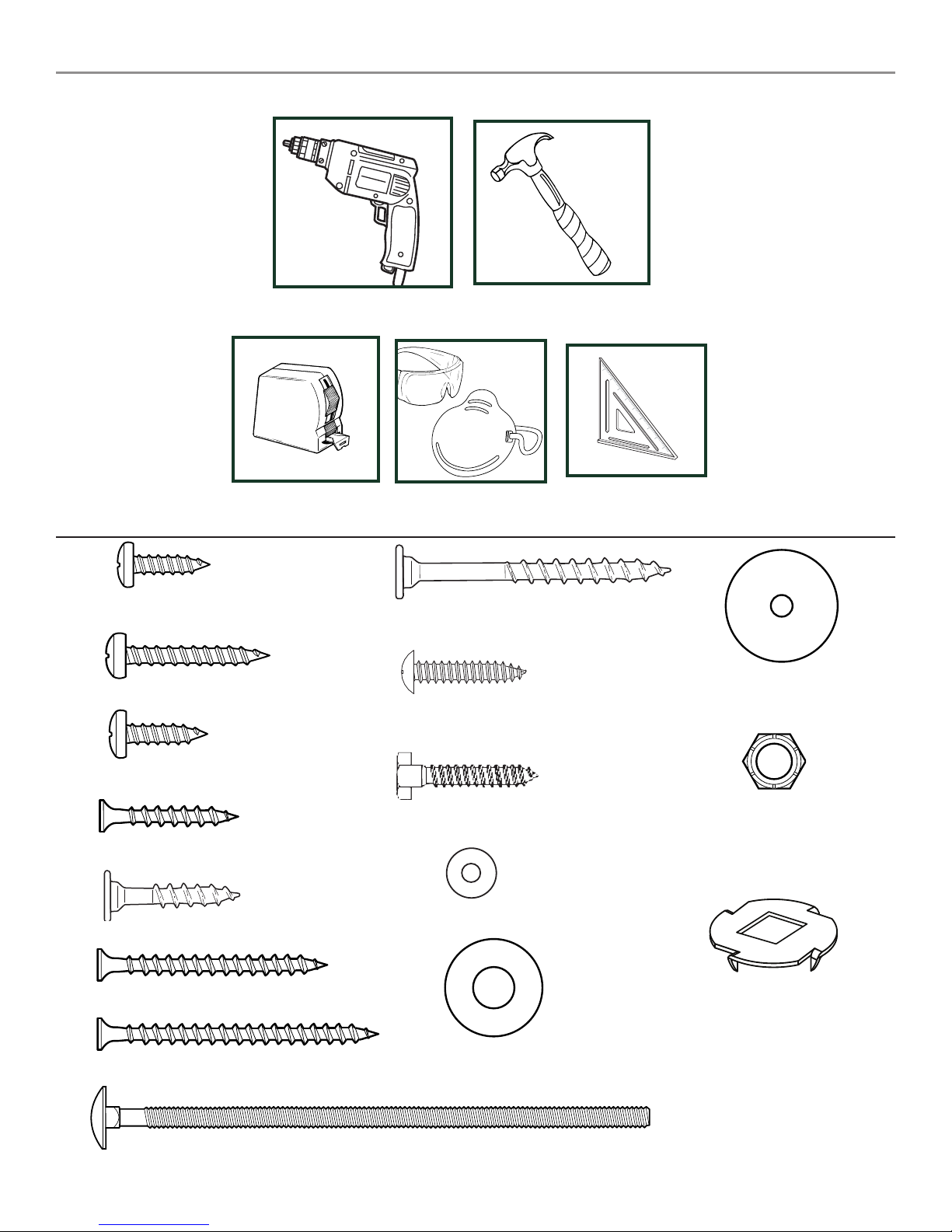
TOOLS REQUIRED
TAPE MEASURE
(2) 1/2'' panhead screws
(4) 1-3/4'' panhead srews
ELECTRIC DRILL
(74) 2" lag screw
(39) 1'' Truss Screws
SAFETY GLASSES
& DUST MASK
HAMMER
CARPENTER'S SQUARE
(6) Tarp Washers
(6) 3/4'' screws
(127) 1-1/4'' screws
(32) 1-1/4'' lag screws
(8) 2'' screws
(412) 2-1/2'' screws
(14) 6-1/2'' Bolts
(4) 5/16''Hex Head Lag Screws
(4) 1/4'' flat washers
(18) 5/16'' flat washers
4
(14) Loc-Nuts
(14) Wood Loc Washers
Page 5

THIS PRODUCT IS
INTENDED FOR USE
BY CHILDREN FROM
AGES 2-10 YEARS
For Home / Residential
Use ONLY
1212 Barberry Drive
Janesville, WI 53545
1-800-888-1232
www.swing-n-slide.com
R
(2) 3X3 TO 4X4
Shelf-Loc
(10) Wrap-Loc
(1) Name Plate
(8) 3X3 TO 2X4
Shelf-Loc
(2) Split Beam bracket
(2) EZ Frame Brackets
(6) Extra-Duty
Swing Hangers
(1) Green Tarp
(4) Step Brackets
Note: (2 Left, 2 Right)
(4) Boomerang
Brackets
(2) 'L' Brackets
(1) T30 Torx® Bit
5
(1) T20 Torx® Bit
CHESAPEAKE
Plan
(1) Plan
Page 6
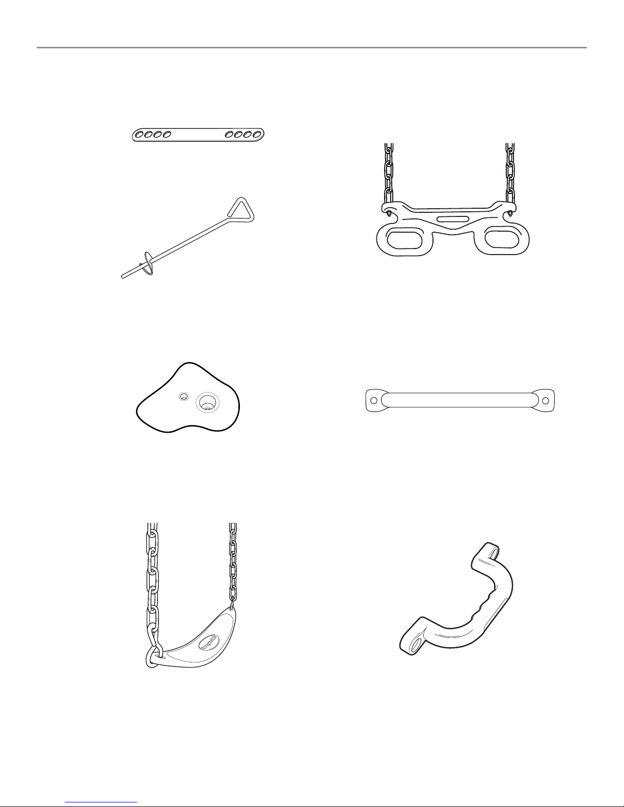
(4) Anchor-It Straps
(4) Anchor-It
(1) Ring-Trap Combo
(8) Climbing Rocks w/ Hardware
(2) Extra Duty-Swing Seats
(9) Metal Rungs
(4) Safety Handles
6
Page 7

(1) 1'' x 3'' x 23-1/2''
(1) 1'' x 4'' x 6-1/4''
(1) 1'' x 4'' x 11''
(1) 1'' x 4'' x 18''
(1) 1'' x 4'' x 20-1/2''
(1) 1'' x 4'' x 25-3/4''
(22) 1'' x 4'' x 30''
(14) 1'' x 4'' x 34''
(1) 1'' x 4'' x 30''
(2) 1'' x 4'' x 36-1/2''
(10) 1'' x 4'' x 41-3/4''
(28) 1'' x 4'' x 47-1/2''
(2) 1'' x 4'' x 74-1/2''
(2) 2'' x 3'' x 59-1/4''
(2) 2'' x 4'' x 11-1/2''
(2) 2'' x 4'' x 15''
(4) 2'' x 4'' x 19-1/4''
(5) 2'' x 4'' x 30''
(2) 2'' x 4'' x 34''
(2) 2'' x 4'' x 36''
(5) 2'' x 4'' x 47-1/2''
(4) 2'' x 4'' x 60''
(2) 2'' x 4'' x 94''
(2) 3'' x 3'' x 78''
(Plastic Coated)
(4) 3'' x 3'' x 94''
(1) 4'' x 4'' x 47-1/2''
(1) 4'' x 5-1/2'' x 94''
(1) 2'' x 4'' x 16''
(Plastic Coated)
(2) 3-1/2'' x 4'' x 94''
CHESAPEAKE DESIGN
7
Page 8
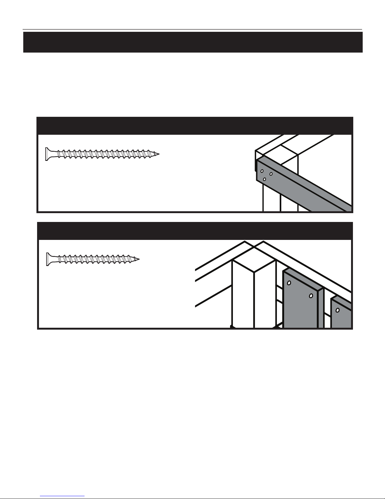
How to select the correct fastener
Use these 2 pictorial guides to help select the correct fastener(s) for the
lumber attachment you are making. Each diagram will highlight the correct
number of fasteners to use, and where to attach them.
1'' x 4'' or 2'' x 4'' to 3'' x 3''
(3) 2-1/2'' screws
Apply 2 1/2" screws to the 2"x4" boards
when attaching to 3"x3" uprights.
1'' x 4'' to 1'' x 4'' or 2'' x 4''
(2) 1-1/4'' screws
Use 1-1/4" screws when mounting 1"
boards to 2"x4" boards.
8
Page 9

Understanding how the Bracket System Works
Wrap-Loc
1
Example of a Shelf-Loc bracket connection.
2
3
CORRECT!
WRONG!
brackets NOT
interlocked!
Shelf-Loc Bracket
Brackets
''clipped''
4
Introduction to the Bracket system
1. ALWAYS Use 1-1/4'' or 2'' lag screws on
all brackets.
2. Brackets ''clip'' to each other. NEVER
position in a non-interlocking position.
NOTE: PLACE SCREWS IN BRACKETS ONLY
WHERE INSTRUCTED. DO NOT
FILL EVERY HOLE IN BRACKET.
THIS WILL LEAD TO HARDWARE
SHORTAGES.
Example of a Shelf-Loc bracket connection.
Look for ''TOP'' stamp on
bracket for correct orientation.
Shelf-Loc
Brackets ClipTogether
GAP
TOP
Top of bracket
Wrap-Loc
Bottom of bracket
(Hole locations close to bottom)
DO NOT USE LAG
SCREWS HERE
Use Lag Screws Only Where
Brackets Attach
9
Page 10

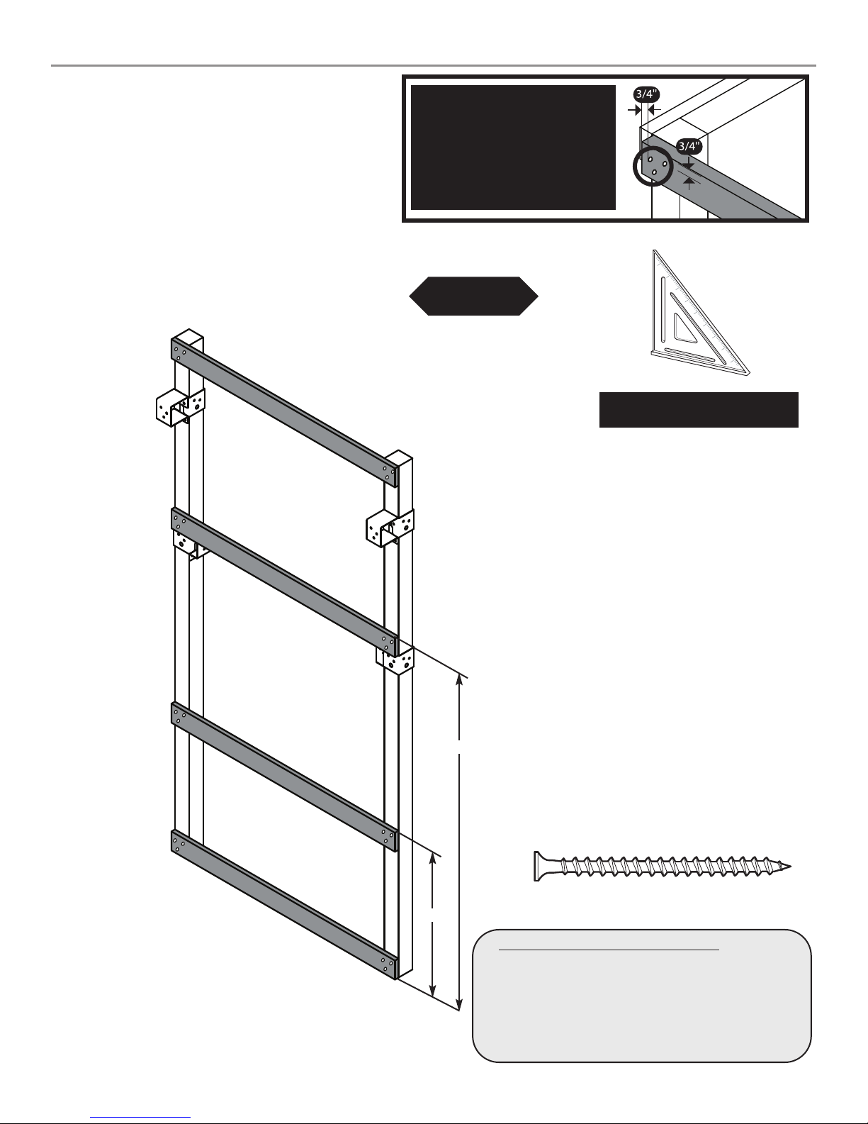
Frame 1 Construction
Look for ‘’TOP’’
stamp on brackets
while installing.
TOP
GAP on
this side
Fig.1
3'' x 3'' x 94''
(2)
2'' Lag Screws
per joint
(2)
1-1/4'' Lag
Screws
per joint
59-1/4''
82-1/2''
(2)
2'' Lag Screws
per joint
(2)
1-1/4'' Lag
Screws
per joint
1-1/4''Lagscrew
2''Lagscrew
Frame 1
A. Frame 1 Construction
1. Measure and position brackets on
3'' x 3'' as shown in (Fig.1).
Note: Secure Shelf Lock with (2) Lag Screws only at this time.
10
Page 11
Frame 1 Construction
1'' x 4'' x 47-1/2''
•WARNING•
Avoid splitting your
lumber by offsetting
your screws at least
3/4’’ from edge.
Fig.1a
(3)
2-1/2'' screws
per joint
Double check to make
sure structure is square
(3)
2-1/2'' screws
per joint
1'' x 4'' x 47-1/2''
1'' x 4'' x 47-1/2''
1'' x 4'' x 47-1/2''
Frame 1
62-3/4''
2-1/2''screw
27''
A. Frame 1 Construction cont.
2. Attach 1'' boards as shown in (Fig. 1a).
11
Page 12

Fig.2
Look for ‘’TOP’’
stamp on brackets
while installing.
TOP
GAP on
this side
Frame 2 Construction
3'' x 3'' x 94''
(2)
1-1/4'' Lag
Screws
per joint
(2)
1-1/4'' Lag
Screws
per joint
Frame 2
1-1/4''Lagscrew
59-1/4''
47-1/4''
B. Frame 2 Construction
1. Measure and position brackets on
3'' x 3'' as shown in (Fig.2).
12
Page 13

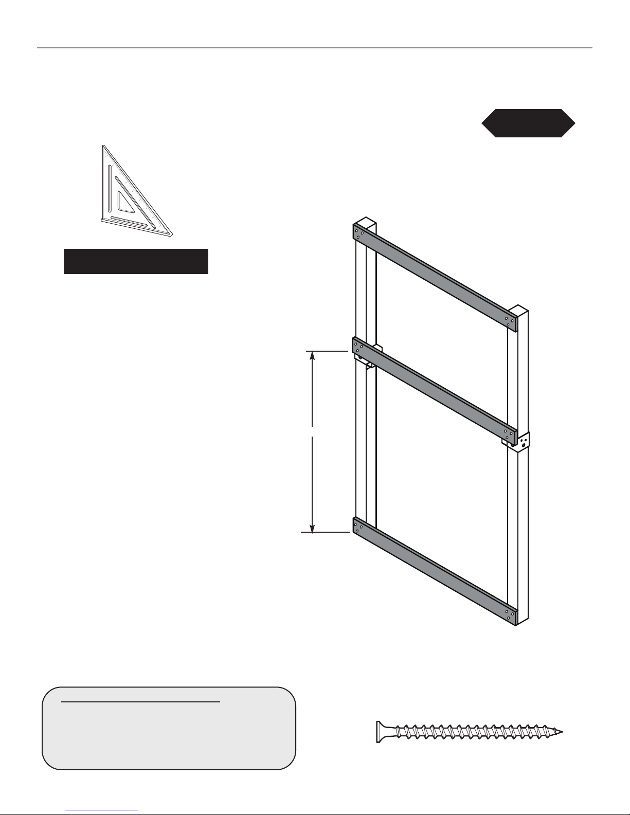
Double check to make
sure structure is square
Frame 2 Construction
1'' x 4'' x 47-1/2''
(3)
2-1/2'' screws
per joint
1'' x 4'' x 47-1/2''
Fig.2a
(3)
2-1/2'' screws
per joint
B. Frame 2 Construction cont.
2. Attach 1'' boards as shown in (Fig. 2a).
53''
Frame 2
2-1/2''screw
13
Page 14
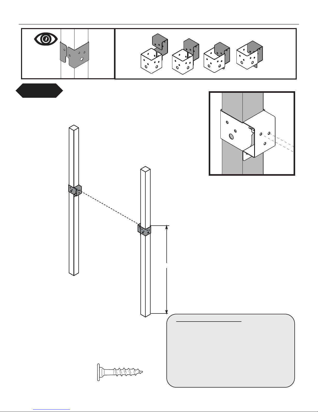
Fig.3
Look for ‘’TOP’’
stamp on brackets
while installing.
TOP
GAP on
this side
Frame 3 Construction
3'' x 3'' x 78''
(2)
1-1/4'' Lag
Screws
per joint
Frame 3
47-1/4''
(2)
1-1/4'' Lag
Screws
per joint
1-1/4''Lagscrew
B. Frame 3 Construction
1. Measure and position brackets on
3'' x 3'' as shown in (Fig. 3).
14
Page 15
Frame 3 Construction
Fig.3a
Double check to make
sure structure is square
(3)
2-1/2'' screws
per joint
47-1/4''
1'' x 4'' x 47-1/2''
1'' x 4'' x 47-1/2''
1'' x 4'' x 47-1/2''
(3)
2-1/2'' screws
per joint
B. Frame 3 Construction cont.
2. Attach 1'' boards as shown in (Fig. 3a).
Frame 3
2-1/2''screw
15
Page 16

Fig. 4
(3)
2-1/2'' screws
per joint
1'' x 4'' x 47-1/2''
2'' x 4'' x 47-1/2''
94''
Top of Board
To Ground
1'' x 4'' x 74-1/2''
Frame 1
D. Frame Construction
1. Install support boards as shown above.
1'' x 4'' x 74-1/2''
(3)
2-1/2'' screws
per joint
2-1/2''screw
16
Page 17

Fig. 5
(3)
2-1/2'' screws
per joint
Double check to make
sure structure is square
2-1/2''screw
Frame 1
(3)
2-1/2'' screws
per joint
Frame 2
47-1/2''
D. Frame Construction cont.
1. Attach Frame Two as shown above.
17
Page 18

Fig. 6
Tip: Flex brackets to make installation of
2'' x 4'' easier
2'' x 4'' x 47-1/2''
(2) 1-1/4'' lag screws
and
(3) 2'' lag screws
per bracket
2'' x 4'' x 47-1/2''
Approx. 1/4''
Fig. 6b
(3)
2'' Lag
Fig. 6a
(2)
1-1/4'' Lag
NOTE: Upper screws are (2) 1-1/4'' Lag
Screws, Lower screws are (3) 2'' Lag
Screws.
E. Install 2'' x 4'' Supports
1. Install 2'' x 4'' boards as shown in (Fig.6), (Fig. 6a),
and (Fig. 6b).
1-1/4''Lagscrew
2''Lagscrew
18
Page 19

Fig. 7
78''
1'' x 4'' x 30''
2'' x 4'' x 30''
Frame 3
(3)
2-1/2'' screws
per joint
2-1/2''screw
F. Frame 3 Construction
1. Measure and position 1'' x 4'' and 2'' x 4'' as shown in (Fig.7).
19
Page 20

Fig. 8
(3)
2-1/2'' screws
per joint
Frame 3
Double check to make
sure structure is square
(3)
2-1/2'' screws
per joint
78''
Frame 1
2-1/2''screw
Frame 2
1. Install Frame 3 by securing 2'' x 4'' and 1'' x 4'' boards as
G. Install Frame 3
shown in (Fig. 8).
(3)
2-1/2'' screws
per joint
20
Page 21

Tip: Flex brackets to make installation of
2'' x 4'' easier
Fig.10
Approx. 1/4''
Fig. 9
Fig.10a
(2)
1-1/4'' Lag
(3)
2'' Lag
NOTE: Upper screws are (2) 1-1/4'' Lag
Screws, Lower screws are (3) 2'' Lag
Screws.
2'' x 4'' x 30''
(2) 1-1/4'' lag screws
(3) 2'' lag screws
per bracket
2'' x 4'' x 30''
and
H. Install 2x4s
1. Install 2'' x 4'' as shown in (Fig. 9), (Fig 10),
and (Fig. 10a).
1-1/4''Lagscrew
2''Lagscrew
21
Page 22

Fig. 11
1'' x 4'' x 47-1/2''
(2)
2-1/2'' screws
per joint
(2)
2-1/2'' screws
per joint
2'' x 4'' x 30''
12''
1'' x 4'' x 41-3/8''
18-1/4''
1'' x 4'' x 41-3/8''
NOTE: There must be a 1/2''
Nominal Gap between all
deck boards.
Fig. 11a
2-1/2'' screws
per joint
(6) 1'' x 4'' x 47-1/2''
(2)
H. Lower Deck Boards
1. Install 1’’ x 4’’ deck boards as shown in (Fig. 11).
2. Install (2) Deck Spacer Board as shown in (Fig. 11).
3. Install (6) Deck Boards as shown in (Fig. 11a).
2-1/2''screw
22
Page 23

Fig. 12
1'' x 4'' x 41-3/8''
SLIDE MOUNT
(2)
2-1/2'' screws
per joint
1-1/4''screw
2-1/2''screw
1'' x 3'' x 23-1/2''
Fig. 12a
SLIDE MOUNT
(4)
1-1/4'' screws
I. End Cap Boards
1. Attach 1'' x 4'' End Cap boards as shown in (Fig. 12),
(Fig 12a).
UNDER DECK VIEW
23
Page 24

Fig. 13
(1) 1'' x 4'' x 41-3/8''
(2)
2-1/2'' screws
per joint
1'' x 4'' x 41-3/8''
(2)
2-1/2'' Screws
per joint
18-1/4''
Fig. 13a
1'' x 4'' x 41-3/8''
2'' x 4'' x 47-1/2''
Install Deck and Support Boards
1. Install Lower Deck Support Board as shown in
(Fig. 13).
2. Install 1’’ x 4’’ deck boards and 2'' x 4'' support
board as shown in (Fig. 13a).
2-1/2''screw
24
Page 25

Fig. 14
(10) 1'' x 4'' x 47-1/2''
(2)
2-1/2'' screws
per joint
NOTE: There must be a 1/2''
Nominal Gap between all
deck boards.
J. Install DeckSupports
1. Install (10) 1'' x 4'' Deck Boards as shown in
(Fig. 14).
2''Lagscrew
Install Swing Beam Support
1. Install 4'' x 4'' Swing Beam Support as shown
in (Fig. 14a).
Fig. 14a
(5)
2'' lag screws
per joint
2-1/2''screw
4'' x 4'' x 47-1/2''
25
Page 26

3-1/2''
12-3/4''
25''
28-3/4''
35''
38-3/4''
51''
54-3/4''
61''
64-3/4''
77''
9
3
3/4
121/4
3
3/4
6
1/4
3
3/4
121/4
3
3/4
6
1/4
3
3/4
121/4
3
3/4
5
3/4
5
1/2
80-3/4''
92''
86-1/2''
94''
9''
Fig. 15
A-FRAME
H. Swing Beam Drill Locations
1. Tap Wood Loc Washer and Carriage Bolt into
swing beam at locations shown in (Fig. 15a).
Fig. 15a
6-1/2'' CARRIAGE BOLT
WOOD LOC
3'' x 5-1/2'' Swing Beam
WASHER
3''
26
Page 27

3'' x 5-1/2'' Swing Beam
WASHER
Fig. 16
LOC-NUT
WASHER
LOC-NUT
Q. Swing Beam Drill Locations
1. Flip 3'' x 5-1/2'' Swing Beam so Carriage Bolts point downward as shown in (Fig. 16).
2. Install the swing hanger onto the beam by sliding over two carriage bolts (refer to (Fig. 15) for placement) and
apply two washers and two loc-nuts per Swing Hanger. Make certain to orient swing hanger as shown
in (Fig 16).
Note: When attaching D-Ring, make certain threads are pointing up. This will help keep the D-Ring from
loosening over time.
4. Repeat for all four hangers.
27
Page 28

Fig. 17
3-1/2'' FACE
Align the edges of the 3-1/2" x 4" legs
with the edges of EZ Frame Bracket
(8) 2-1/2’’ Screws
3-1/2'' FACE
3'' FACE
R. A-Frame Assembly
1. layout 3-1/2'' x 4’’s and 2'' x 4'' as
shown in (Fig. 17) and (Fig. 17a).
2. Align EZ Frame Bracket with face of
4'' x 4''s.
3. Secure EZ Frame Bracket with (8)
2-1/2'' screws to 3-1/2'' x 4''s
making sure they are flush with each
other.
4. Secure 2'' x 4'' to 3-1/2'' x 4''s as
shown in (Fig. 17a).
5. Flip over and add 2nd bracket.
Repeat steps 2 and 3.
Fig. 17a
3-1/2" x 4" x 94''
49-1/2"
(4)
2-1/2'' screws
2" x 4" x 47-1/2"
EZ Frame Bracket
3-1/2" x 4" x 94''
(4)
2-1/2'' screws
3-1/2'' FACE
2-1/2''screw
93"
2828
Page 29

Washer
2-1/2'' screws
Fig. 18
Loc-Nut
2-1/2''screw
S. A-Frame Assembly cont.
1. Align EZ-Frame Bracket with carriage bolts on Swing Beam as shown in (Fig. 15).
2. Attach A-Frame beam to Swing Beam using (2) washers and (2) Loc-Nuts and 2 screws as shown in (Fig. 18).
3. Tighten Loc-Nut. Repeat on other bracket.
29
Page 30

T. Swing Beam Attachment.
1. Position Split-Brackets on 4'' x 4'' x 47-1/2''
as shown in (Fig. 19).
2. With the help of others, lift A-Frame and
Swing Beam Assembly and center onto unit as
shown in (Fig. 19a).
3. Secure as shown in (Fig 19a).
Fig. 19a
Fig. 19
22''
Swing Beam
View from Deck
Swing Beam
2''Lagscrew
x 8 (each bracket)
30
Page 31

NOTE: There must be a 2-1/4''
Nominal Gap between all
barrier boards.
(2)
1-1/4'' screws
per joint
(7)1'' x 4''x 30''
Fig. 20
1-1/4''screw
Install Barrier Boards
1. Install boards as shown in (Fig. 20). Space boards
evenly.
31
Page 32

Fig. 21
2-1/2'' screws
per joint
(5)
1''x 4''x 18''
1''x 4''x 25-3/4''
(5)
2-1/2'' screws
per joint
Fig. 22
(2)
1-1/4'' screws
per joint
(1)2'' x 4''x 34''
2'' x 4''
Must Be Secured
From Outside
Barrier
(4)1'' x 4''x 34''
2-1/2''screw
V. Barrier Boards
1. Install 1'' barrier boards as shown.
NOTE: There must be a 1''
Nominal Gap between all
barrier boards.
1-1/4''screw
V. Barrier Boards
1. Install 2'' x 4'' and 1'' x 4'' barrier boards evenly
spaced as shown in (Fig. 22).
32
Page 33

Fig. 23
(8) 1'' x 4'' x 34''
(2)
1-1/4'' screws
per joint
NOTE: There must be a 1-1/2''
Nominal Gap between all
barrier boards.
1-1/4''screw
V. Barrier Boards
1. Install barrier boards evenly spaced as shown in
(Fig. 23).
2'' x 4''
Must Be Secured
From Outside
Barrier
(2)
1-1/4'' screws
per joint
(2)1'' x 4''x 34''
(1)2'' x 4''x 34''
Fig. 24
2. Install barrier boards as shown in (Fig. 24).
33
Page 34

Fig. 25
(2)
2'' screws
per joint
(2)2'' x 4''x 36''
1''x 4''x 47-1/2''
3/4'' Overhang
(4)
2-1/2'' screws
22''
(4)
2'' screws
2''screw
2-1/2''screw
V. Taro Support Boards
1. Install 2'' x 4'' and 1'' x 4'' tarp support boards as shown in (Fig. 25).
34
Page 35

Fig. 26
3/4’’
3/4''screw
Y. Install Tarp.
1. Install tarp as shown in (Fig. 26).
2. Secure tarp in six locations (Fig 26a).
Fig. 26a
35
Page 36

Fig. 27
2-1/2''screw
V. Climbing Wall Support Board
22-1/4''
2''x 3''x 59-1/4''
(2)
2-1/2'' screws
per joint
1. Install 2'' x 3'' Climbing Wall support board as shown in (Fig. 27).
36
Page 37

Climbing Wall.
Fig. 28
TOP
1. Attach (14) 1'' x 4'' boards to (2) 2'' x 4'' boards
and install on unit as shown in (Fig. 28).
2. Attach (1) 2'' x 4'' board as shown in (Fig. 28).
3. Attach Climbing Wall to unit as shown in
(Fig. 28a).
NNOOTTEE::
5' Climbing Rock Wall will require
88 CClliimmbbiinngg RRoocckkss
Fig. 28b
(2)"T" nuts
3-7/8''
(14) 1'' x 4'' x 30''
2'' x 4'' x 60''
(1) 2'' x 4'' x 30''
2'' x 4'' x 60''
3-1/8'' GAP
22-1/4''
1/2'' GAP BETWEEN
1'' BOARDS
(2)
2-1/2'' screws
(Per joint)
3/8" Holes
(2) 1-1/4'' Hex Head Bolts
(1) Loc Washer per bolt
(1) Flat Washer per bolt
Hold (rock)
Climbing Rock Installation
1. Mark locations of Climbing Rocks on the Climbing
Wall in a pattern that will easily allow your child to
climb to the deck. Make sure the bolt hole locations
are clear of wall supports before drilling.
2. Drill holes through the wall at the desired locations
using a 3/8" drill bit. Install Climbing Rocks as
shown in (Fig. 28b).
3. Make sure the Climbing Wall and Climbing Rock
connections are secure before allowing any children
to play on the Climbing Wall.
Fig. 28a
2-1/2''screw
(3)
2-1/2'' screws
(Both Sides)
37
Page 38

Fig. 29
16-1/2''
2-1/2'' screw
Rung Ladder Support
1. Install 2'' x 3'' Rung Ladder Support as shown in (Fig. 29).
2''x 3''x 59-1/4''
2-1/2'' Deck Screws
(4)
(2 per joint)
38
Page 39

Fig. 30
(2)
2-1/2'' Screws
per joint
2-3/4''
1'' x 4'' x 20-1/2''
10-1/8''
10-1/8''
10-1/8''
10-1/8''
10-1/8''
(8)
2'' Lag Screws
(2 per rung)
Rung Ladder
2'' Lag screw
2-1/2'' screw
1. Install Ladder Rungs as shown in (Fig. 30).
2. Install 1'' x 4'' gap filler so that top of board is 2-3/4''
below the bottom of the deck support as shown in
(Fig. 30).
39
Page 40

Fig. 31
Fig. 31a
2'' x 4'' x 11-1/2''
Fig. 31b
2'' x 4'' x 11-1/2''
2'' x 4'' x 19-1/4''
2'' x 4'' x 19-1/4''
(3)
2-1/2'' Deck Screws
per joint
(3) 1'' x 4'' x 41-3/8''
(2)
2-1/2'' Deck Screws
per joint
1-1/4'' screw
2-1/2'' screw
Picnic Table
1'' x 4'' x 11''
1. Install 2'' x 4'' boards as shown in (Fig. 31).
2. Attach 1'' x 4'' boards as shown in (Fig. 31a). Make
certain to evenly space boards.
3. Attach Picnic Table support centered underneath the
Picnic table as shown in (Fig. 31b).
UNDER DECK VIEW
(1)
1-1/4'' Deck Screws
per joint
40
Page 41

Fig. 32
2'' x 4'' x 15''
X2
2'' x 4'' x 15''
(3)
1'' Truss Head Screws
per joint
(2)
Boomerang
Brackets
Fig. 32a
2-1/2'' screw
(2) 1'' x 4'' x 36-1/2
(2)
2-1/2'' Deck Screws
per joint
1''Truss Head
screw
Double check to make
sure structure is square
Picnic Bench
1. Using (2) ‘Boomerang brackets’ Install 2'' x 4'' boards
as shown in (Fig. 32). Sandwich ‘Boomerang Bracket’
between horizontal and vertical 2'' x 4''s. Make certain
bottom edge of Boomerang Bracket touches the ground.
2. Attach 1'' x 4'' boards as shown in (Fig. 32a). Make
boards flush with end of 2'' x 4'' support with no gap
inbetween.
3. Attach Picnic Table support centered underneath the
Picnic table as shown in (Fig. 32b).
Fig. 32b
1'' x 4'' x 6-1/4''
UNDER DECK VIEW
1-1/4'' screw
(1)
1-1/4'' Deck Screws
per joint
41
Page 42

BOARD INVENTORY:
Identify the illustrated boards below to build your Monkey Bars set.
19-1/4"
(2) 2" x 4" x 19-1/4''
60"
(2) 2" x 4" x 60''
94"
(2) 2" x 4" x 94''
Fig. 33
2" x 4" x 60"
Unit
19-1/2''
(5) Metal Rungs
2" x 4" x 60"
13"
13" 13" 13"
2" x 4" x 60"
4-1/2"
ASSEMBLY INSTRUCTIONS
1. On two 2" x 4" x 60" boards, measure and mark five rung positions, centered at intervals shown in (Fig. 33).
Attach Rungs to 2'' x 4''s using (2) 2'' Lag Screws per rung.
1''Truss Head
screw
FLUSH
2'' Lag screw
Fig. 34
2. Position the 2" x 4" x 19-1/4" steps to the inside of
the 2" x 4" x 94'' posts as indicated in (Fig. 35) and
(Fig. 36). Mark the bottom of each step location on the
2" x 4" posts. Attach a step bracket to the posts at each
marked location using three 1-1/4" screws per bracket.
(6)
1'' Truss Head
screws
per bracket
Place 2" x 4" x 19-1/4'' steps on top of brackets and
secure using three 1-1/4" screws per bracket.
3. Secure the steps to the ladder posts using (2) 2-1/2''
screws per joint as shown in (Fig. 35).
4. AttachMonkey Bars Ladder to Monkey Bars assembly
using (2) Boomerang Brackets as shown in (Fig. 34).
42
Page 43

25 1/8
39 1/8
24 9/16
38 9/16
24 9/16
25 1/8
38 9/16
39 1/8
22 1/4
Fig. 35
Left Side
2'' x 4'' x 94''
Right Side
2'' x 4'' x 94''
2-1/2'' screw
Fig. 36
(6)
1'' Truss Head
screws
per bracket
(2)
2-1/2'' screws
per joint
74-1/2"
Ladder Rung
2''x4''x19-1/4''
Ladder Rung
2''x4''x19-1/4''
1-1/4'' screw
(2)
2-1/2'' screws
per joint
(6)
1-1/4'' screws
per bracket
16"
1''Truss Head
screw
ASSEMBLY INSTRUCTIONS:
5. With the help of others, position the finished assembly to the unit (Fig. 36). Determine post locations. remove
assembly and dig two 16" deep holes at the previously determined spots. Reposition assembly to unit placing
posts in the holes.
6. Level the assembly and attach to the unit using six 1" Truss Head screws per bracket. Fill in holes and compact
earth around posts.
20-1/2"
9-1/2"
14"
43
Page 44

Fig. 37
1''x 4''x 30''CenterArch
(3)
2-1/2'' screws
per joint
2-1/2'' screw
Crowning Arch
1. Install 1'' x 4'' Arched board as shown in (Fig. 37).
44
Page 45

washer
1-3/4'' Panhead screw
Fig. 38
11"
Deck Surface
P. Safety Handles.
1. Mount safety handles in the ladder and
climbing wall openings approximately 11''
above the deck surface (Fig. 38).
Fig. 38a
metal strap
Anchor-It
stake
Anchor-It
Flat Washer
1-1/2"
lag bolt
S. Anchor-It Installation.
Instructions for Anchoring Swing•N•Slide
Activity Centers
1. Determine the final location of your activity
center.
2. Place the Anchor-It stakes adjacent to the base
and near the corners of your activity center (at
the bottom of the legs on swing sets) and twist
the auger-style stakes into the ground until only
the loop is exposed.
3. Place the metal strap through the loop of the
Anchor-It stake and secure it to the unit with a
lag screw and washer as illustrated to the right.
Note: Attach the strap to the unit with as little
play as possible using whatever holes in the
strap that work best.
45
Page 46

W. Slide Installation.
1. Install Slide centered in the provided
opening as shown in (Fig. 39).
2. Attach Stake to end of slide as shown in
(Fig. 39a).
Fig. 39
Fig. 39a
(2)
1-1/4'' screws
per joint
2'' x 4'' x 16''
1'' Truss Screw
Use truss head screws to
to secure slide to deck.
2'' Above Ground
46
Page 47

47
Page 48

Questions???...
Call our Customer Service Department
at 1-800-888-1232
© PlayCore Inc. 2009 Printed In USA LA 5996
 Loading...