

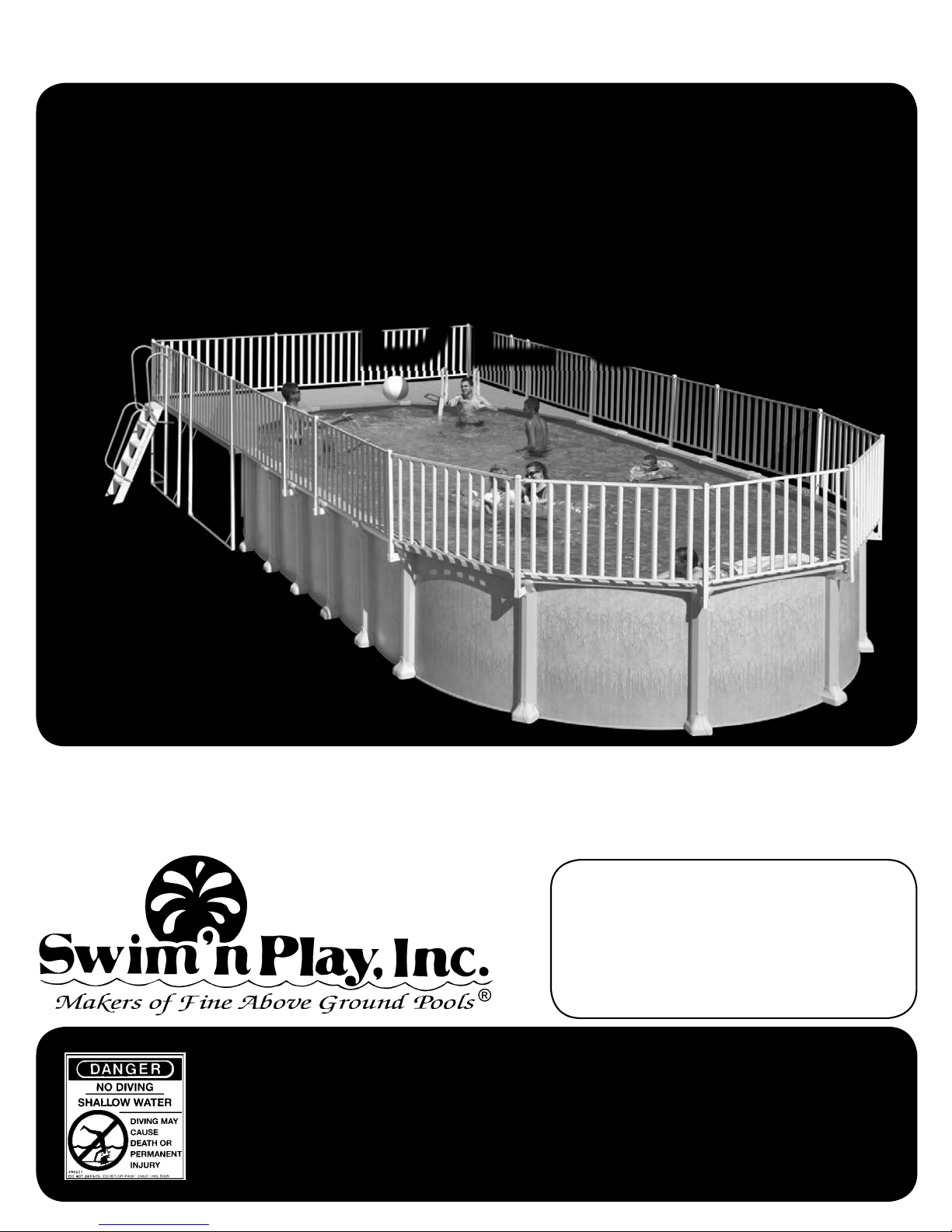
Swim'n Play end deck Assembly Instructions Manual
ASSEMBLY INSTRUCTIONS
12 ft.
15 ft.
18 ft.
END
DECKS
READ THROUGH AND UNDERSTAND ALL THE STEPS TO THIS INSTALLATION BEFORE
ATTEMPTING TO INSTALL EITHER YOUR POOL OR YOUR DECK.
IF YOUR POOL IS ALREADY INSTALLED IT MAY BE NECESSARY TO LOWER THE WATER
LEVEL IN YOUR POOL DOWN TO 2’ TO ENABLE YOU TO PROPERLY INSTALL THIS DECK.
DO NOT DIVE OR JUMP into your pool. Your pool is approximately 4' deep.
It is not designed for diving or jumping. If you dive or jump into your pool
you run the risk of permanent injury or death. Alert all visitors and family
Part # 420867
313 REGINA AVENUE
RAHWAY, NEW JERSEY 07065-4891
Phone: (732) 574-1500
Fax: (732) 574-1551
www.swimnplay.com
E-mail: info@swimnplay.com
DANGER
of this and point out all warning labels supplied.
ADULT SUPERVISION REQUIRED

GENERAL
Take time to follow the instructions and do
things right the fi rst time. Read all instructions
prior to starting. Before you start, check to see
that you have the correct number of parts. Use
your parts list which is broken down by carton.
The manufacturer reserves the right to revise,
change or modify construction of their product.
CONTRACT INSTALLATIONS
The manufacturer is in no way affi liated with
any professional installer . Therefore the manufacturer can assume no responsibility, for errors in
installation by the home owner or said professional installer . If you have your deck installed by
others, please supervise to be sure they comply
with the proper installation techniques shown.
Their past experience or short cuts may not
cover the latest improvements in our decks. Do
not allow any short cuts of any nature.
the pool with a minimum height of 48”.
A barrier is necessary to provide protection
against potential drowning and near drowning
and is not a substitute for constant supervision of
children.
A barrier is a fence, wall, or a combination
thereof which completely surrounds the swimming pool and obstructs access to the swimming
pool. Barriers must comply with local and national
building codes and the US Consumer Product
Safety Commission.
These are minimum fencing and barrier requirements. Check your local building codes for
other requirements they may request. Optional
fencing kits are available, Please contact your local dealer.
If pool covers are used for safety barriers
they should comply with ASTM F 1346 “Standard Performance Specifi cation for Safety
Covers and Labeling Requirements for All Covers
for Swimming Pools, Spas and Hot Tubs.”
LOCAL CODES
Local building code may require obtaining a
building permit and may have regulations on set
backs, barriers, devices and other conditions that
must be followed. Any after market or home built
deck should be built to the local building code
requirements, including load capacity and fencing
requirements.
Local electrical code may require obtaining
a building permit and may have regulations on
setbacks, devices and other conditions that must
be followed.
All electrical outlet connections should be a
minimum of 5 feet from the outside perimeter of
the wall of the pool. From 5-10 feet there should
be either a fi xed connection (outlet box) or twist-
lock connection with a GFCI. Connect power
cords to a 3-wire grounding-type outlet only.
Severe electrical shock could result if you install your pump or fi lter on a deck. They could fall
into the water , causing severe shock or electrocution. Do not install on a deck or other surface at,
above or slightly below the top SEAT of the pool.
GETTING STARTED
Unpack and identify all the parts to your
deck using the enclosed packing list.
TO ASSEMBLE THE DECK YOU WILL NEED:
1. DRILL WITH A 7/64", 5/32", 3/16" AND 5/16" BIT
2. 7/16" WRENCH
3. #3 POINT PHILLIPS SCREW DRIVER
4. MEASURING TAPE AND MARKING PENCIL
ATTENTION
DECKS ARE MADE FOR
52 INCH DEEP POOLS
IF YOUR POOL IS 48" DEEP
YOU WILL HAVE TO DIG A TRENCH
OR CUT THE BOTTOM OF THE POSTS
(4 INCHES) IN ORDER TO LEVEL THE HEIGHT OF
THE DECK WITH THE HEIGHT OF YOUR POOL.
BARRIER REQUIREMENTS
If the distance from the top of the assembled
pool is less than 48” vertically from the surrounding grade, a fence or barrier is needed to surround
THE BASE OF THE DECK MUST BE LEVEL
WITH THE TOP LEDGE OF YOUR POOL
2

1
LADDER
Clear out and level the ground in the location where your deck is to be installed.
Use the Assembly Drawings below for reference while assembling your deck
(Note: ladder can be installed on either side).
During assemly please note that the ledges on the pool are to be removed where the
deck meets the pool. The extension on the front of the deck will replace your pool legde.
Please refer to Step 7.
18’ END DECK
ASSEMBLY
DRAWINGS
(VIEWED FROM ABOVE)
LADDER
LADDER
15’ END DECK
12’ END DECK
3

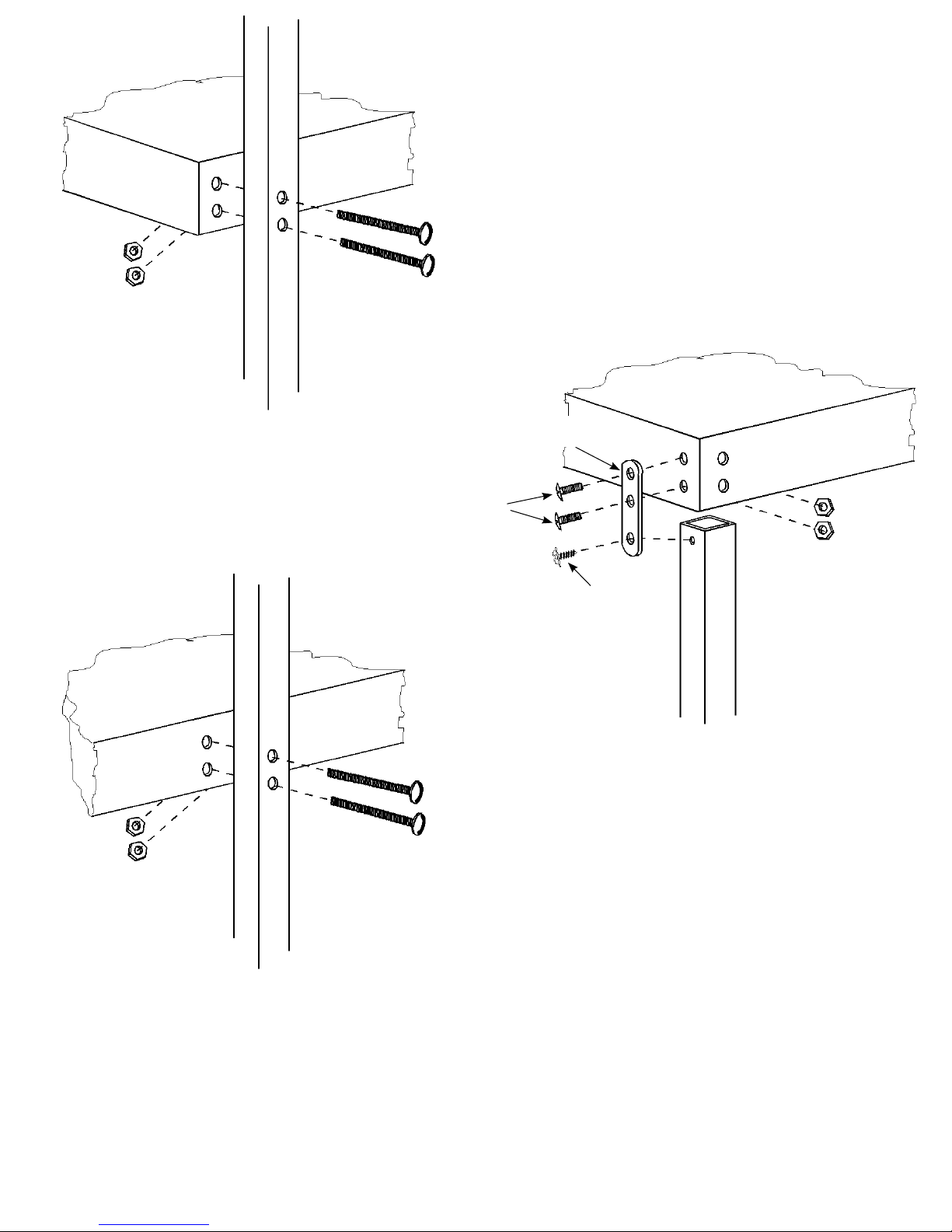
IMPORTANT: ONLY HAND TIGHTEN SCREWS AT THIS TIME
2
Elevate your two outside deck sections using either patio blocks or saw horses.
Attach the Posts referring to the Close-up Illustrations below and on the following
page for the proper assembly procedure for each location.
ONLY HAND TIGHTEN THE SCREWS at this time.
CLOSE-UPS
#2a & #2b
CLOSE-UP
#5
CLOSE-UP #3 CLOSE-UP #3
POST FOR LADDER
ATTACHES ON
EITHER SIDE
CLOSE-UP #3
CLOSE-UP #4
POOL
CLOSE-UPS
#2a & #2b
15’ END DECK
&
18’ END DECK
CLOSE-UPS
#2a & #2b
CLOSE-UP
#5
CLOSE-UP #3 CLOSE-UP #3
POST FOR LADDER
ATTACHES ON
EITHER SIDE
CLOSE-UP #3
CLOSE-UP #4
CLOSE-UPS
#2a & #2b
POOL
CLOSE UP #2a
HEX
HEX
NUTS
1/2”
SCREWS
CORNER POST
BRACKET
NUTS
12’ END DECK
CLOSE UP #2b
HEX
NUTS
CORNER
POST
LONG
POST
BRACKET
2” SCREWS
1/4” x 20 x 2”
TRUSS HEAD SCREW
1/4” x 20
HEX NUT
1/4” x 20 x 1/2”
TRUSS HEAD SCREW
4
1/2” SHEET
METAL SCREW
HEX
NUTS
DECK TOP
2” SCREWS
CLOSE-UP #4
CLOSE-UP #3
DECK TOP
LONG POST
SHORT ANGLE
SUPPORT BAR
1/2”
SCREWS
DECK TOP
HEX
NUTS
1/2”
SHEET
METAL
SCREW
49-5/16” POST
HEX
NUTS
LONG POST
CLOSE-UP #5
Finally, attach another Long Square Post for the Ladder on either side of your deck in the
location illustrated for your deck on the prior page.
Choose the location of your ladder depending on which side of the deck will provide the most
convenient access to the pool.
Fasten this Post to the deck referring to Close-Up #5 above for the proper assembly procedure.
2” SCREWS
5
IMPORTANT: ONLY HAND TIGHTEN SCREWS AT THIS TIME
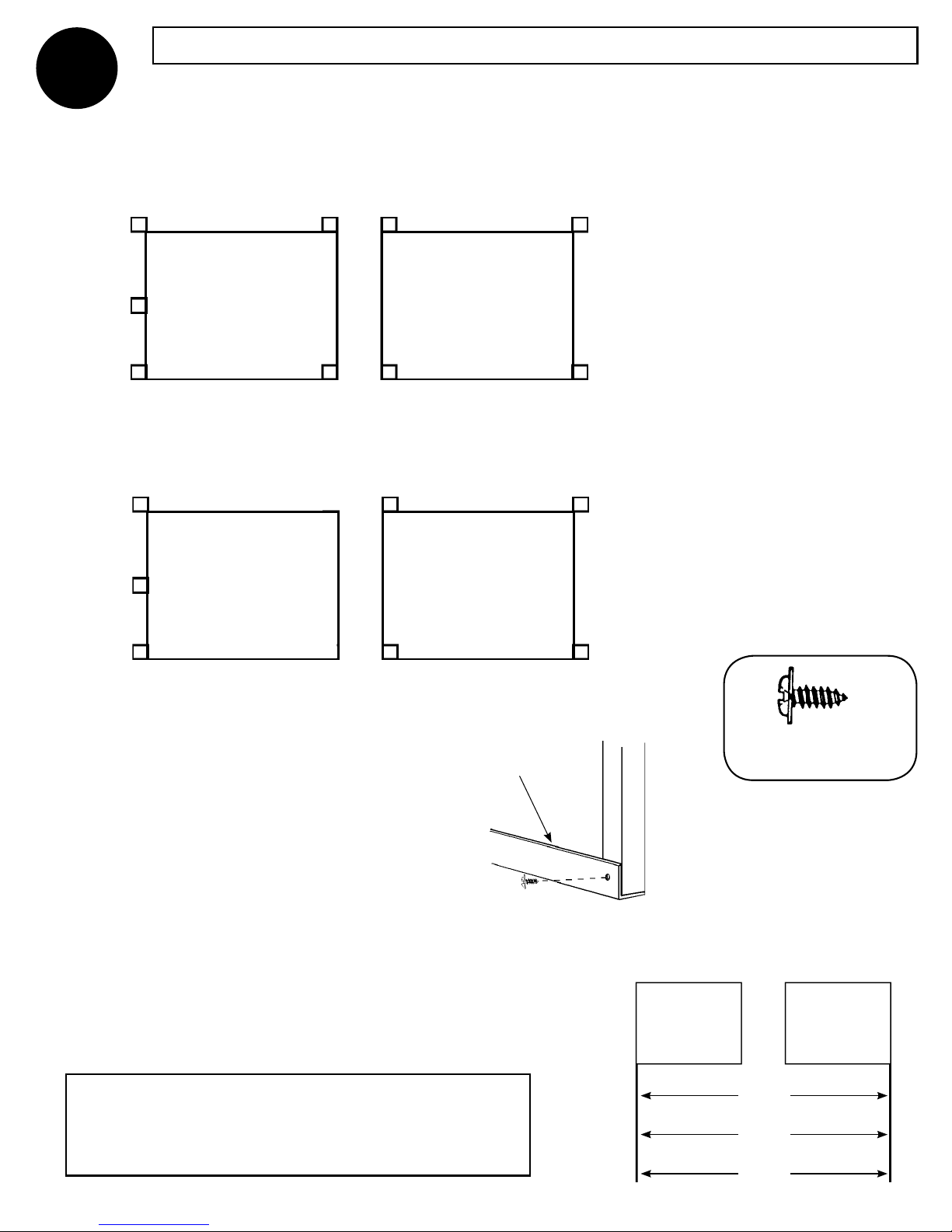
3
Position the Bottom Support Channels (long “L” shaped pieces) at the bottoms of the
Posts according to the illustration below for your size deck.
Note the different sizes. (The illustrations are as viewing the deck from above with the
Ladder to be installed on the left side.)
73-3/4”
73-3/4”
15’ END DECK
58-7/8”
58-7/8” 58-7/8”58-7/8”
&
18’ END DECK
73-3/4”
POOL
75” 73-3/4”
73-3/4”
58-7/8” 58-7/8” 58-7/8”58-7/8”
75” 73-3/4”
POOL
Having positioned the Bottom Support
Channels in their proper locations as
illustrated above, attach them to the
bottom of the Posts (including the Post
for the Ladder) using 1/2” Sheet Metal
Screws as shown at right.
BOTTOM SUPPORT
CHANNEL
1/2” SHEET
METAL SCREW
12’ END DECK
1/2” SHEET
METAL SCREW
BOTTOM
OF POST
NOTE: On the 12’ End Deck, you must now attach
1 side of remaining 72½” Bottom Support Channel
to the outside Posts nearest the pool. See right.
12’ END DECK
52-5/16
15’ END DECK
66-3/4
18’ END DECK
79-7/16
6
 Loading...