

Swift Group Select 122 2020, Select 164 2020, Select 174 2020, Select 144 2020, Select 184 2020 Owner's Handbook Manual

CREATING SMILES FOR LIFE
Swi Group
Owner’s Handbook
Select Van Conversion
Issued August 2019
Part No.1436690


INTRODUCTION
INTRODUCTION
Dear owner
Thank you for deciding to buy one of our new
motorhomes.
We are sure you will enjoy many happy hours
in it and we hope the information and hints in
this handbook will heighten your enjoyment.
The handbook has been designed to give
you a general guide to the care, use and
maintenance of your motorhome. Whether
you are a new or an experienced motorhomer
the hints will help to protect your investment.
The information contained will answer most
of your queries, but if there are any aspects
which are not covered please consult your
appointed dealer. We would suggest you
make a note of your dealers name and
contact information below.
Important - please quote the base VIN
(vehicle identication number) in all
correspondence with your dealer or Swift
Group Limited (Swift), this can be found on
the lower corner of the front windscreen or
on the Fiat plate positioned on the front cross
member within the engine compartment.
All the illustrations and descriptive matter in
this handbook are intended to give a general
idea of the motorhome. Changing market
and supply situations may prevent us from
maintaining the exact specication details
in this handbook. We therefore reserve the
right to alter specications as materials and
conditions demand.
Dealers are not agents of Swift Group Limited
and have absolutely no authorit y to bind Swift
Group Limited by any express or implied
undertaking or representation.
On-Line Handbooks
Throughout the season, specications and
equipment details contained within this
handbook may change. Please refer to our
online handbooks (www.swiftgroup.co.uk)
for the most up-to-date version of your
handbook.
Handbook Denitions
Customers should note that this handbook
contains general information for the use
and care of your product and the Technical
Handbook, which contains technical
information, weights and dimensions of your
product.
Happy touring!
Dealer Name:
.........................................................................
Telephone Number:
.........................................................................
E-mail:
.........................................................................
VIN:
.........................................................................
Sales Tel:
.........................................................................
Service Centre Tel:
.........................................................................
Parts Tel:
.........................................................................
First Service Due:
.........................................................................
7

SWIFT TALK
SWIFT TALK / ECWVTA / NCC APPROVAL
Swift Talk
Swift Talk is the new central forum for the Swift
community online. A place for all those united in
their love of caravanning, motorhomes, holiday
homes and touring in general, to share their
experiences, meet new friends and nd out
a world of information on how to enjoy their
touring lifestyle.
The site is packed full of features that actively
encourage members, not only to liaise with the
Swift Group via the forums, but also interact
with each other through publishing their own
content, uploading and sharing photos and
video, and even posting their own blogs for the
community to follow.
Swift Talk is the rst place to learn about new
product launches, events and Swift Group
news, it’s also the rst place customers can
go to as a quick reference to frequently asked
questions or to actively take part in the forums;
providing valuable feedback on Swift Group
products and customer service.
The new online community can even be used
to create your own groups, perfect for Owners’
Clubs, dealers and exhibitors to attract new
members, publicise and build awareness for
upcoming events, rallies and shows.
Anyone who owns, uses, or is thinking of
buying a Swift Group caravan, motorhome
or holiday home, or would just like to be part
of the growing Swift community is actively
encouraged to sign up, create their own
content, and start talking!
Just visit www.swift-talk.co.uk and become
part of a unique online experience.
TAL K
8

CONTENTS
Warranty Information 11
The Motorhome Code 19
Preparing for the Road 23
En Route 31
Safety & Security 35
Arrival at Site 41
Connecting Services 43
Electrical Systems 65
Equipment Details 93
Motorhome Care 117
Technical Information 131
Useful Information 145
Index 148
CONTENTS
9

10

WARRANTY INFORMATION
Warranty 12
Supplier contacts 15
Service inspection 16
WARRANTY INFORMATION
11

WARRANTY
12
WARRANTY INFORMATION
Panel Van Conversion
Motorhome Warranty
All the illustrations and descriptive matter in
this handbook are intended to give a general
idea of the motorhome. Changing market and
supply situations and our policy of continuous
product development may prevent us from
maintaining the exact specications detailed
in this handbook. We therefore reserve the
right to alter specications as materials and
conditions demand.
Dealers are not agents of Swift Group
Limited (“Swift”) and have absolutely no
authority to bind the manufacturer by
any express or implied undertaking or
representation.
Note: To register your warranty, please use
the Connect Direct Registration process, by
doing so you are agreeing that you have had
the details of the warranty and the annual
service arrangements fully explained. This in
no way aects your statutory rights under the
Consumer Rights Act.
Your Coach-built motorhome has four
warranties:
Base Vehicle Warranty – provided by Fiat
Your vehicle is a panel van conversion
motorhome which utilises a Fiat base vehicle.
For a panel van conversion motorhome, Swift
takes a panel van as supplied by Fiat and ts
out the interior of the van for habitation. Fiat
provides a manufacturer’s warranty for the
base vehicle as supplied to Swift by them.
For any issues with the base vehicle warranty
please contact your local Fiat dealer. This
Motorhome Warranty does not cover any parts
of your motorhome that are covered by the
Fiat manufacturer’s warranty. Your base vehicle
warranty is subject to the terms and conditions
contained in the Fiat handbook supplied with
the base vehicle and the vehicle must be
serviced in accordance with Fiat requirements.
SuperSure Warranty – provided by Swift
For all parts or ttings of your panel van
conversion motorhome other than the Fiat
base vehicle, Swift will repair (or at its option,
replace) any defective parts or ttings for
3 years from the date of purchase (or hire
purchase) subject to conditions, terms and
exclusions below.
Panel Van Conversion Body Shell Warranty
(“Body Shell Warranty”) – provided by Swift
Swift will repair (or at its option, replace) any
defects with the panel van conversion to the
body shell for 3 years from the date of purchase
(or hire purchase), subject to the conditions,
terms and exclusions below.
This Motorhome Warranty does not cover any
parts of your motorhome that are covered by
the Fiat manufacturer’s warranty.
Conditions for the SuperSure and Body Shell
Warranties
1. You must ensure that the habitation part
of your motorhome has an Annual Service
(see clause 2 below) within 90 days before
or 60 days after each anniversary of
the original date of purchase. In order to
preserve your SuperSure and Body Shell
Warranties the third Annual Service must,
however, be carried out before the expiry of
the 36 month period from the original date
of purchase. If you have not performed
an Annual Service then Swift will not be
obliged to perform any work under the
applicable warranty. Original VAT invoices
must be retained as proof that Annual
Service have been carried out.
2. The Annual Service on the body shell
and habitation area must be carried out
in accordance with the requirements in
this handbook. You will be responsible for
any charges made for an Annual Service.
If the Annual Service is performed by an
authorised Swift Group Service Centre
then Swift warrants that the Annual Service
has been performed correctly. If the Annual
Service is performed by an unauthorised
repairer or service centre then if the
Annual Service has not been performed
in accordance with the requirements
in this handbook and/or work has been
performed on your motorhome that is
defective or faulty, then Swift will not be
obliged to perform any work under this
Warranty (insofar as it relates to defective
or faulty work or defective Annual Service

WARRANTY
WARRANTY INFORMATION
3. The benet of the SuperSure and Body 3.
All new motorhomes must be registered
with Swift within 6 weeks of purchase as
new.
4. The benet of the SuperSure and Body
Shell Warranties may be transferred to
a new owner if the motorhome is resold, provided that the motorhome has
been serviced in accordance with the
requirements of this handbook, and details
of the change of ownership have been
supplied to Swift using the change of
ownership form set out in this handbook
as soon as reasonably practicable after the
change.
5. If any repairs are identied as being
necessary to the body shell or habitation
areas during an Annual Service or
otherwise, Swift will only pay for Warranty
work performed by an authorised Swift
Group Service Centre. The motorhome
must be made available to an authorised
Swift Group Service Centre within 6 weeks
of the date the repair need was identied
for the work to be carried out. The cost
of transporting, towing or moving the
motorhome by any means to or from the
place of repair is the responsibility of the
owner.
6. The SuperSure and Body Shell Warranties
only apply to motorhomes purchased and
used primarily within the UK. Please refer
to the Fiat handbook for use of the base
vehicle outside the UK.
Terms
7. The Body Shell Warranty covers any defect
with the joints and seals of the panel van
conversion. This includes body leaks,
delamination of oors, and water ingress
through any permanently sealed seam
joints which relate to the conversion of the
panel van. This Motorhome Warranty does
not cover any parts of your motorhome
that are covered by the Fiat manufacturer’s
warranty.
8. In the rst 12 months the SuperSure
Warranty will cover any defect other than
those specied in the Exclusions below.
9. In the years 2 and 3 the SuperSure
Warranty will only cover any defect with the
following components:
• Electrical System: PSU, battery charger,
Smart Command and interior lighting units
(excluding bulbs).
• Water system: water heater, fresh water
tank, water pump, water gauges, taps and
shower head.
• Cooker: the cooker unit including grill, oven,
burners, igniter, and ame failure device.
• Refrigerator: gas igniter, ame failure device,
door seal condenser, gas control valve, 12v
and 230v heater elements, gas thermostat,
230v thermostat and 230v temperature
control switch.
• Cassette Toilet: the cassette toilet (excluding
seals, valves and glands).
• Heating system: thermostat, motor,
switches, control unit, gas heater, ame
failure device and igniter (exluding ducting
and ttings).
• Windows: the functionality of the opening
and closing system (stays, handles and
catches) and a warranty against the cracking
of the acrylic, Excludes fading.
• Upholstery: zips, seams and colour fastness.
In years 2 and 3, any defect specied in the
Exclusions will not be covered. Exclusions
Exclusions
10. Swift shall not be liable under the
SuperSure and Body Shell Warranties for
any defect related to or arising from the
following:
1. The failure of a component for reasons
of fair wear and tear;
2. Damage resulting from freezing, re,
over-heating or accidents (whether
caused by the user or a third party);
3. Misuse of any component;
4. Normal deterioration, corrosion,
intrusion of foreign or harmful bodies,
lack of servicing or negligence of
any person other than Swift which
13

WARRANTY & ASSISTANCE
WARRANTY INFORMATION
causes stoppage of or impairment to
the function of any component of the
motorhome;
5. Replacement of parts which have
reached the end of their eective
working life because of age and/or
usage;
6. Cleaning or adjustment of any
assemblies;
7. Damage caused by any abrasive
cleaners
8. Cosmetic nishes to kitchen sinks,
cooker tops, vanity units, shower trays;
and/or
9. Routine maintenance items which are
part of the annual service including
lubricants, rubber gas hose, the cleaning
of the heater and fridge ues, the
replacement of gas jets, the resealing
and/or replacement of shower room
sealant, and the adjustment and
lubrication of locks.
10. Should you have an enquiry or require
assistance with a problem, we hope that
this guide will be of assistance to you.
11. In addition to the exclusions above, in years
2 and 3 of the SuperSure Warranty Period,
Swift Group Limited shall not be liable under
this Warranty for any defects related to:
• Any microwave
• Factory tted leisure battery after 12 months
of date of purchase
12. Swift shall also not be liable under the
SuperSure, and Body Shell Warranties
if the motorhome has been neglected,
misused, modied or used for hire or reward
or if the identication marks (chassis/VIN
numbers) have been removed or defaced.
The motorhome will be deemed to have
been neglected if it has not been serviced
and maintained as stated in this handbook
or any repairs being identied as necessary
at an Annual Service or by a Swift Group
Service Centre have not been carried out in
a reasonable time.
You have legal rights under UK law governing
the sale of consumer goods. This Warranty
does not aect your legal rights.
The name and address of the Warranty
provider is:
Swift Group Limited, Dunswell Road,
Cottingham, East Yorkshire, HU16 4JX
To make a claim under this Warranty, contact
the Swift Group Dealer which supplied your
motorhome. Alternatively, details of your
nearest authorised Swift Group Service Centre
can be obtained by contacting the Swift Group
Customer Service Department on 01482
875740, or enquiring on the website www.
swiftgroup.co.uk
Change of Ownership
You can transfer the remainder of any three
year ‘Supersure warranty’ and the three year
‘Body shell’ warranty, details of how to do this
can be found at the rear of this handbook.
Swift Connect Direct
You have access to an online system which is
for all Swift models. A password will be issued
to you, to enable you to interact with us.
To access the system, called ‘Swift Connect
Direct’, your initial log in details will be emailed
to you once your supplying dealer has
registered your ownership with us.
Please log in and create your own prole.
Should you have issues with accessing Swift
Connect Direct, please contact our Customer
Services Team.
What to do if you Require Assistance
Should you have an enquiry or require
assistance with a problem, we hope that this
guide will be of assistance to you.
Please follow these steps:
1. Check the Owners Handbook, paying
particular attention to the fault nding
advice at the back of the book.
2. Contact your supplying dealer for
assistance.
14

SWIFT CONNECT / ASSISTANCE
WARRANTY INFORMATION
If you need to contact Swift Group Limited,
please be aware of the following:
1. When contacting Swift Group, please quote
your name, postcode and VIN (Vehicle
Identication Number). This can be found at
the bottom of the front windscreen and on
the side of the sliding door. Also within the
engine bay.
2. In most instances, the Customer Service
Team will involve your dealer in resolving the
issue you are experiencing.
3. Check our website www.swiftgroup.co.uk
and enter the help and advice section
which provides answers to frequently asked
questions and how to contact us.
Sargent Electrical Services
Unit 39, Tokenspire Business
Park,Beverley, East Yorkshire, HU17
0TB
Phone: 01482 678981
Fax: 01482 678987
E-mail: support@sargentltd.co.uk
Truma UK Ltd.
Park lane, Dove Valley Park,
South Derbyshire, DE65 5BG
Phone: 01283 586020
Fax: 01283 586029
technical@trumauk.com
Thetford Ltd.
Unit 6, Brookelds Way, Manvers,
Dearne Valley, Rotherham,
South Yorkshire, S63 5DL
Phone - 0844 997 1960
Fax - 0844 997 1961
Email - infogb@thetford.eu
4. If you are contacting the company by
email, letter or fax, the Customer Service
Team will respond to you within ve
working days from the date of receiving the
correspondence.
5. Please be aware that Swift Group Limited
cannot send parts direct from the factory.
In all cases, without exception, your dealer
must place the order for you.
Supplier contacts
A number of Swift Group suppliers manage
their own Technical and Warranty related
queries. Where a customer has a question
relating to a product manufactured by a
company listed below, we would advise that the
rst contact should be directly with them.
https://sargentltd.co.uk
https://www.truma.com/uk/en/home/
index.php
https://www.thetford-europe.com
Dometic (UK) Ltd
Dometic House, The Brewery,
Blandford St Mary, Dorset, DT11 9LS
Phone: 0844 626 0133
Email: technical@dometic.co.uk
https://www.dometic.com/en-gb/uk
15

SERVICE INSPECTION
WARRANTY INFORMATION
Annual service / inspection record
In order to comply with the warranty, you must
have your motorhome inspected and serviced
in accordance with the warranty.
We highly recommend that you have your
Motorhome serviced by a Swift Group
Approved Service Centre who have direct
access to our online Customer Service
system, Connect. This system provides them
with the ability to order approved parts and
ensure that any product upgrades which
may be available for your Motorhome can be
oered to you and carried out as part of the
service. In the unfortunate event that an issue
requires attention under warranty then a Swift
Group Approved Service Centre are able to
submit a warranty claim to the Swift Group
for processing, and deal with the issue for
you from start to nish. All of our Swift Group
Approved Service Centres are provided with up
to date technical information and have access
to current repair methods giving you peace
of mind that any defect has been repaired
eectively.
It is important that the owner’s handbook
is stamped on the appropriate page by the
authorised Swift Group Service Centre.
Failure to do this will invalidate the warranty and
the transfer of the warranty on the change of
ownership.
The inspection should take approximately two
hours and will cover the areas dealt with in the
annual service check list. Any areas requiring
service and/or maintenance will be highlighted
by your dealer and we recommend that you
authorise any necessary work to be carried out.
Just as the engine/gearbox/roadwheels need
regular servicing by your chassis dealer, so
there are components in your conversion that
need regular maintenance by your motorhome
dealer.
These include the gas and electrical systems
and the seals in the bodywork. Your dealer will
complete the record in this handbook to show
that the work has been carried out.
1. Damp and lamination test.
2. Chassis and chassis to body security.
3. Motorhome step.
4. Road lights, wiring and reectors.
5. Internal lights and 12V DC system.
6. Water heater - gas and 230V AC.
7. Hob, grill and oven.
8. Refrigerator 230V AC, 12V DC and gas.
9. Gas system.
10. Water pump, taps and water system.
11. Mains 230V AC system.
12. Windows and ttings.
13. Roof lights.
14. Furniture hinges/stays etc.
15. Exterior locks and hinges.
16. All internal vents.
17. Seals.
18. Blinds and y screens.
19. Blown air heating systems.
20. Smoke alarm and battery
21. Carbon monoxide detector and battery
16

Annual service/inspection record
INSPECTION RECORD STAMPS
WARRANTY INFORMATION
Motorhome model:
Registration number
Chassis number
Registration date
2nd service
DAT E:
DEALER’S STAMP
We certify that an annual service has been
carried out in accordance with the handbook.
4th service
Date:
Dealer’s Stamp
1st service
DAT E:
DEALER’S STAMP
We certify that an annual service has been
carried out in accordance with the handbook.
3rd service
DAT E:
DEALER’S STAMP
We certify that an annual service has been
carried out in accordance with the handbook.
5th service
Date:
Dealer’s Stamp
We certify that an annual service has been
carried out in accordance with the handbook.
6th service
DAT E:
DEALER’S STAMP
We certify that an annual service has been
carried out in accordance with the handbook.
We certify that an annual service has been
carried out in accordance with the handbook.
7th service
DAT E:
DEALER’S STAMP
We certify that an annual service has been
carried out in accordance with the handbook.
17

INSPECTION RECORD STAMPS
WARRANTY INFORMATION
8th service
DAT E:
DEALER’S STAMP
We certify that an annual service has been
carried out in accordance with the handbook.
10th service
DAT E:
DEALER’S STAMP
We certify that an annual service has been
carried out in accordance with the handbook.
12th service
DAT E:
DEALER’S STAMP
9th service
DAT E:
DEALER’S STAMP
We certify that an annual service has been
carried out in accordance with the handbook.
11th service
DAT E:
DEALER’S STAMP
We certify that an annual service has been
carried out in accordance with the handbook.
13th service
DAT E:
DEALER’S STAMP
18
We certify that an annual service has been
carried out in accordance with the handbook.
We certify that an annual service has been
carried out in accordance with the handbook.

MOTORHOME CODE
Code of conduct 20
The Country code 22
The Coastal code 22
MOTORHOME CODE
19

CODE OF CONDUCT
20
Camp sites
Arrivals
Report to reception immediately on arrival.
Vehicle Movement
Keep to roadways unless otherwise directed.
Adhere to speed limits. Note that these are
MOTORHOME CODE
generally 10 mph. (Remember that the stopping
distance on grass is considerably greater than
on tarmac.)
Only a person in possession of a current driving
licence may drive on the site.
Park correctly as advised on your pitch. Where
possible leave 20 feet of free space around
your vehicle.
Use of Site Appliances
Use the electrical mains hook-up in the correct
manner and with caution. Ensure that all fresh
water taps/connections are turned o after
use. Have care and consideration when using
all facilities (toilets and showers etc) and leave
clean and tidy. Young children should be
supervised.
Waste Disposal
If the vehicle is not tted with a waste water
tank, a suitable receptacle should be placed
below all waste water outlet pipes. Do not let
these containers overow. Dispose of all waste
water where instructed. Empty euent from
chemical toilets where instructed.
To avoid possible damage to sewage
purication works, only approved chemical
uids must be used. Under no circumstances
should coal tar, phenol or caustic-based uids
be used.
Disposable nappies and similar bulky items
must not be put into chemical closet emptying
points but should be wrapped in a polythene
bag and placed in the container provided.
Place all litter in containers marked for the
purpose.
Noise
Do not make excessive noise. Children should
be restrained from making excessive noise.
Flying kites, drones and model aircraft, and the
use of items like catapults or air-guns, as well as
ball games, should not be permitted among, or
close to other vehicles.
Musical instruments, record players, radios
and televisions should not be used to the
inconvenience of other people on the site.
Open and close doors quietly. Power
generators must be adequately silenced and
used with consideration.
Dogs and other Pets
All dogs and other pets should be kept under
control. Unless permission has been granted,
no animal should be allowed loose on the site
and leads must not exceed 10ft.
No animals should be allowed in the shower/
toilet blocks.
Do not let dogs foul the site.
Fire Precautions
Adhere to and take note of re precautions
noting the whereabouts of the re points.
WARNING: Provide one dry powder
re extinguisher of an approved type or
complying with EN3-7 or ISO 7165, of at least
1kg capacity, by the main exterior door and
a re blanket next to the cooker. Familiarise
yourself with the operating instructions
on your re extinguisher and the local re
precaution arrangements.
When using a dry powder extinguisher it is
suggested that the motorhome be evacuated
until the powder has settled, to avoid inhalation.
Code of conduct
Unless permission has been granted,
barbecues should not be used. If permission
is given, consideration should be given to the
annoyance that can be caused to other users
of the site.
Open res are not allowed.
Awnings and Tents
Awnings and tents should only be used when
permission has been obtained. When on
grass and staying for more than a few days,
the ground sheet and/or side aps of awnings
should be periodically raised in order to avoid
damage to the ground.

CODE OF CONDUCT & THE COUNTRY CODE
MOTORHOME CODE
Departure
Leave the pitch clean and tidy.
On leaving, check out with reception paying the
required fees.
Wild camping
Camping away from licensed sites, without the
permission from the land owner or his agents, is
not allowed in the United Kingdom.
When permission has been granted, all aspects
of this Code should be adhered to.
On no account should:
a. Litter be disposed of other than in the
receptacles provided.
b. Water be allowed to escape from the
vehicle.
c. Chemical toilets be emptied except into the
disposal places agreed with the land owner.
d. Washing or similar be hung outside the
vehicle.
Parking
Motorhomes should only be parked in
approved places.
When using the facilities of a motorhome, care
and consideration should be given to those
around them.
Driving
Before moving o, elevated rooights and
aerials should be lowered and correctly
secured, and top hinged windows closed.
Likewise all doors and access lockers for
gas containers and chemical toilets must be
properly secured.
Exterior steps should be properly retracted
and secured. When the vehicle is in motion
it is compulsory for all front seat passengers
and rear seat passengers to wear seat belts,
where tted. When using a motorhome on
either the public highway or private roads the
Highway Code should be complied with and full
consideration given to other road users.
In the event of a motorhome travelling slowly
the driver of the motorhome should, where
possible, pull over in order to let other trac
pass.
WARNING: When travelling, refuelling
or on a ferry ensure the gas system is fully
isolated at source.
Handbooks (Chassis & Converter)
Before using a motorhome all aspects of
the handbooks, produced by the chassis
manufacturer and the converter, must be read
and adhered to.
The separate chassis manufacturer handbook
refers to your motorhome chassis and base
vehicle including care and maintenance.
Link to Fiat handbook
21

THE COASTAL CODE
Environment
Care and consideration should be taken to
protect the environment. Observe the Country
and Coastal Codes.
The Country code
Enjoy the countryside but respect its life and
MOTORHOME CODE
work.
More people than ever before are exploring the
countryside, interested in farming, plant life, bird
watching or just observing the general wildlife.
Whatever your interest, there is a lot to learn,
but please observe the following code:
1. Guard against all risk of res. Hay and
heathland catch alight easily and once
ablaze are very dicult to put out.
Remember: re spreads quickly.
2. Fasten all gates.
3. Keep your dog under proper control.
4. Keep to the paths across farm land.
5. Avoid damaging fences, hedges and walls.
6. Leave no litter.
7. Safeguard water supplies.
8. Protect wildlife, wild plants and trees.
9. Go carefully on country roads.
10. Respect the life of the countryside. The
Coastal code
The coastal code
As our coastlines are increasingly used for
recreation and education, the following
suggestions are made to enable us to enjoy
our inheritance and preserve it for posterity.
Do not trample about, or move rocks
unnecessarily.
Do not frighten seals or seabirds.
Do not spill detergents, solvents or fuel from
boats as these can kill marine life.
When sailing, moderate your speed - the wash
from a fast boat can destroy banks and nests.
Live molluscs and crustaceans need not be
collected as souvenirs - dead shells can usually
be found.
Shellsh can take years to grow and nes
can be imposed for not observing national
regulations.
Do not pull up seaweeds unnecessarily. Make
your visit instructive - not destructive.
Look at material - don’t remove it. Take notes
and photographs, not specimens.
Observe by-laws and be considerate to others.
National Trust property and Country Parks have
regulations to protect the wildlife. Follow these
and the Country and Coastal Codes.
22

PREPARING FOR THE ROAD
Before Moving O 24
Motorhome Terms 24
Loading of Vehicle 25
Large Storage Areas 25
Tyres 26
Dedicated Travelling Passenger Seats 26
Seat belts & legislation 27
Child seats 27
Airbag 28
Three Point Seat Belts 28
Driving Licence 28
Advice on towing 28
European touring 29
PREPARING FOR THE ROAD
23

BEFORE MOVING OFF & MOTORHOME TERMS
PREPARING FOR THE ROAD
Before moving o
Check:
• Gas cylinders are correctly positioned,
secured and turned o unless using en-route
heating.
• All gas operated appliances have been
isolated except en route heating where tted
and in use.
• Loose articles are stowed securely. Do not
stow tins, bottles or heavy items in overhead
lockers.
• All lockers and cupboard doors are closed
and secured.
• Tables are stored or locked in their transit
position.
• Fridge is on 12V or auto operation and door
lock is set.
• 230V mains input socket ap is securely
closed.
• All drain valves are closed.
• Tyre pressures
• Exterior roof rack ladder / bike rack is
secured (where tted).
• All windows/doors/rooights are closed and
secured.
• Exterior step (where tted) is retracted /
folded in.
• Special attention must be taken to ensure
all top hinged windows as well as rooights
are closed when in transit. All units should be
fully closed and latched to prevent damage.
The motorhome rear and side sliding door
should also be locked.
WAR NING: Large and/or voluminous items
should be stored securely before travelling.
Motorhome terms
Mass in Running Order:
The mass of the motorhome equipped to
the motorhome manufacturers standard
specication, as stated by the manufacturer.
The MRO comprises the ex-works weight of
the motorhome, including the driver, 90% fuel
capacity, 1 x LPG gas cylinder @10kg and
standard xtures & ttings in compliance with
European Regulation No. 1230/2012 (Masses
& Dimensions)
Note: The mass of the motorhome in running
order contains provision for the masses of
liquids, gas etc. (see Mass in Running Order in
the Technical Section). Part of this provision
can also be utilised as additional payload, if
for example, you wish to travel with no gas
cylinders.
Note: If you travel with water in the fresh
water tank or waste tank, the payload will be
reduced accordingly.
Note: Quoted MRO is subject to tolerance,
due to weight variation of materials used in
Motorhome construction.
Maximum User Payload:
The maximum allowable weight to be put into
the motorhome whilst it is being driven. This is
made up of 4 sections:
Personal eects, conventional load, optional
equipment and essential habitation equipment.
The Maximum User Payload is the dierence
between the Maximum Technically Permissible
Laden Mass and the Mass in Running Order.
Personal Eects:
Those items which a user can choose to carry
in a motorhome and which are not included
as Essential Habitation Equipment or Optional
equipment.
Conventional Load:
A mass allowance for each designated
passenger seat.
24

LOADING OF VEHICLE
PREPARING FOR THE ROAD
Optional Equipment:
Items made available by the manufacturer over
and above the standard specication of the
motorhome.
Essential Habitation:
A mass allowance for liquids in systems not
accounted for within the MRO.
Maximum Technically Permissible
Laden Mass:
The maximum weight for which the motorhome
is designed for normal use when being driven
on a road, laden.
This mass takes into account specic
operating conditions including factors such as
the strength of materials, loading capacity of
tyres etc.
Gross Train Weight:
The maximum combined weight of the
motorhome and trailer.
WARNING: Under no circumstances
should the Maximum Technically Permissible
Laden Mass of this motorhome be exceeded
Nose weight on towed trailers:
The static mass of the trailer towing device on
the rear of the towing vehicle.
When measuring the noseweight it is important
that the trailer is loaded.
The trailer is intended to be towed slightly
nose heavy. The nose weight can be adjusted
by distribution of the load. The nose weight
should be approximately 7% of the actual laden
weight (but not greater than the hitch capacity)
and at the same time suit the motorhome
requirements. See ‘Advice on Towing’ page 28.
Loading of vehicle
WARNING: Loads must not be exceeded.
The driver is responsible for arranging the
loads so that they comply with the technical
weight limits of the specic motorhome
model.
See Technical handbook.
Correct weight distribution is an important
factor in ensuring your vehicle is well balanced
and easy to drive. It is therefore necessary to
load your motorhome carefully making sure all
heavy articles are evenly distributed and are
preferably placed in the lower lockers or bed
boxes.
WARNING: Do not travel with televisions
or microwaves in overhead lockers unless
the appliance was supplied tted to your
motorhome by the manufacturer.
Although it is essential to ensure that the total
weight of your motorhome does not exceed the
stipulated Maximum Technically Permissible
Laden Mass, (MTPLM), it is important to
remember that the front and rear axles also
have individual maximum weights which must
not be exceeded.
To ensure adequate road holding the load on
the front axle, under all conditions, must not
be less than 40% or more than 70% of the
total weight.
Ensure you distribute the payload equally on
each side of the vehicle to avoid an imbalance.
25

TYRES & PASSENGER SEATING
PREPARING FOR THE ROAD
These weights, together with the MTPLM, can
be found on the statutory plate axed to the
forward edge side sliding door.
WARNING: Turn o all gas appliances
while the vehicle is in motion. If a en-route
heating system is tted isolate all appliances
except the heater.
WARNING: Please take care to ensure you
have allowed for the masses of all the items
you intend to carry in your motorhome e.g.
passengers, optional equipment, essential
habitational equipment and personal eects
such as clothing, food, pets, bicycles,
sailboards and sports equipment etc.
Note: Care must be taken to ensure that
exterior doors are closed, locked and that all
possessions are properly stored and secured
before setting o on any journey.
Large storage areas
The large storage areas provided in some
motorhome layouts are designed solely for
the purpose of carrying personal possessions,
these areas must not be used:
• As a habitation area (eg living, sleeping or
cooking).
• To carry passengers, animals or livestock.
• For the installation (or use) of any LPG gas
operated appliances (unless supplied tted by
the manufacturer).
• For carrying LPG gas cylinders.
• To carry any ammable liquids, unless
properly stored, sealed and secured.
• For the operation of an electrical generator.
• In such a way that the load exceeds the
MTPLM, and/or minimum and maximum axle
loads.
Care must be taken to ensure that exterior
doors are closed, locked and that all
possessions are properly stored and secured
before setting o on any journey.
Tyres
If a wheel or tyre is changed any replacement
must be of the same type of construction
and size.
The law requires that the tyres and pressures
must be suitable for the use to which they
are being put. The minimum tread depth
must be 1.6mm throughout a continuous
band comprising the centre three-quarters
of the breadth of the tread and around the
circumference of the tyre.
Please refer to the base vehicle manufacturer’s
handbook for tyre pressure information.
This may also be displayed in the driver’s or
passenger’s door aperture.
The motorhome tyre pressure noted in the
Technical book are the pressures stated by
Fiat for your vehicle calculated in a fully laden
condition. If you are not running fully laden,
reduced pressures could be used but please
seek clarication from the tyre manufacturer.
Dedicated travelling
passenger seating
Seat belts are tted to all travelling seats.
Travelling seats are designated by the
manufacturer and vary according to the layout
you have purchased. Each seat is homologated
i.e. tested to all relevant safety requirements.
NEVER travel in or attempt to install a seatbelt
to a non-designated seat.
WARNING: Side facing seats are designed
for habitational use only, not for when the
vehicle is in motion.
26

THREE POINT SEAT BELT
VEHICLE CLASSIFICATIONS
& ADVICE ON TOWING
PREPARING FOR THE ROAD
Seat belts and legislation
Designated driver and passenger seats are
tted with seat belts and MUST be worn when
travelling.
All children up to 135cm (4’5”) in height, or 12
years of age, whichever is reached rst must
use a child car seat or booster seat suitable for
their age and weight.
Children over 135cm (4’5”) in height or aged 12
years and over must wear a seat belt.
Note: It is the legal responsibility of the driver
To ensure children aged up to 14 years old are
suitably restrained.
For passengers aged 14 and over, it is their
responsibility (not the driver) that a seat belt is
worn.
Seat belts are tted for your safety and must
be worn unless a ‘Certicate of Exemption from
Compulsory Seat Belt Wearing’ is held. This
Certicate must be produced if asked for by the
Police – seat belt oences can result in a ne.
Child seats
Choosing/Buying
Go to a reputable retailer such as Halford’s,
Mothercare, John Lewis etc. Most reputable
retailers will have trained child seat advisers
on site and will oer a tting service. Ask the
advisor to t various seats to the vehicle. Once
a correctly tted seat has been installed, satisfy
yourself on it’s suitability for your child and the
vehicle before buying as it is important to use a
correctly tting seat in your motorhome.
WARNING: The child seat you use in your
car may not be suitable for mounting on a
motorhome seat.
WARNING: Choose the right seat for your
child’s height and weight.
Height-based seats
Height-based seats are known as ‘i-Size’ seats.
They must be rear-facing until your child is over
15 months old. Your child can use a forwardfacing child car seat when they’re over 15
months old.
You must check the seat to make sure it’s
suitable for the height of your child.
Only EU-approved height-based child car
seats can be used in the UK. These have a label
showing a capital ‘E’ in a circle and ‘R129’.
Weight-based seats
The seat your child can use (and the way they
must be restrained in it) depends on their
weight.
Only EU-approved weight-based child car
seats can be used in the UK. These have a label
showing a capital ‘E’ in a circle and ‘ECE R44’.
You may be able to choose from more than one
type of seat in the group for your child’s weight.
For more information visit www.gov.uk
Never t or use a second hand car seat. It could
have been damaged and may not meet modern
standards. The tting instructions may also be
missing.
Positioning/Fitting
Dependant upon the child seat type, the most
suitable position for the child seat to be tted
may be the front passenger seat of the cab
(NOTE airbag advice on following page) or the
window seat of the forward facing rear seat.
The isle seat in the rear is NOT a recommended
position. Advice should always be taken from
the retailer on the suitability and security of the
seat in the motorhome. Read and follow the
child seat manufacturer’s instructions for tting
the seat.
All Swift motorhomes are tted with inertia reel
seat belts, however, the child seat must be tight
in the adult seat. Push all your weight into the
child seat as you tighten the belt.
Keep a copy of the child seat tting instruction
in the motorhome for easy reference.
Any doubts, ask an advisor to show you how to
correctly install the seat.
27

THREE POINT SEAT BELT
VEHICLE CLASSIFICATIONS
& ADVICE ON TOWING
PREPARING FOR THE ROAD
Airbag
Never t a rear facing child restraint in a seat
with an active airbag in front of it.
Forward-facing child restraints should be
positioned as far back from the airbag as
possible. Check the base vehicle handbook.
Three point seat belts
This section refers to the seat belts located in
the habitation area of your motorhome.
Fastening the seat belt:
Insert tongue into buckle; a positive ‘click’
indicates correct assembly.
Releasing the seat belt:
Press the red release button, the tongue will be
ejected from the buckle.
• The belt is designed for use by one person
and must not be put around a child seated on
a person’s lap.
• The belt is suitable for restraining most child
seats and boosters.
• The belt should at all times be adjusted and
used in accordance with the instructions. No
excessive slackness should be present.
• Once installed the diagonal should pass
across the centre of the shoulder and the
buckle should lie just on or below the hip.
• Avoid twisting the webbing during use.
Webbing must not be allowed to chafe
against sharp edges.
• Do not make alterations or additions to the
belt.
• Belts that have been cut, frayed, damaged or
stressed through impact should be replaced.
After impact the motorhome anchorage
points should also be checked.
• To clean use warm soapy water only.
• Periodic inspection of the installation will
ensure reliability of the seat belt.
Driving licence
Licences issued to drivers who passed their
car driving test before 1st January 1997
include categories B+E and C1+E which gives
them entitlement to drive motor vehicles up to
7500kg MTPLM.
Drivers who passed their test on or after this
date have category B entitlement only, which
restricts the entitlement to motor vehicles with
up to 8 passenger seats and an MTPLM of up
to 3500kg with trailers up to 750kg MTPLM
(4250kg gross train weight) or larger trailers
providing the combination of the trailer and
towing vehicle does not exceed 3500kg and
the MTPLM of the trailer does not exceed the
unladen weight of the towing vehicle.
Drivers who passed their test on or after the
1st January 1997 will need to take an additional
test(s) to gain the C1+E entitlement.
Advice on towing
The towing capability of each motorhome
diers depending on the specic chassis and
engine types, (see ‘Towing Capabilities Table’ in
your specication section).
This table takes account of the maximum front
and rear axle loadings as well as the minimum
front axle loading in two conditions, MRO and
MTPLM condition.
Towing in these, and any other condition
requires sensible loading and distribution of
payloads to ensure the requirements of the
towing capability table are met.
When towing, the demands on both the
vehicle and driver increase. A trailer reduces
manoeuvrability, the ability to climb hills,
acceleration and braking capacity and makes
the vehicle handle and corner dierently. It
will also increase the fuel consumption of the
vehicle.
Always brake in good time. Special care must
be taken when descending gradients. Change
down before going down a steep hill so the
engine can act as a brake. Ensure that the
towing vehicle tyre pressures are correct and
adjusted for full load conditions and that the
trailer tyre pressures are as recommended by
the trailer manufacturer. Regularly check the
operation of trailer brakes and lights.
For maximum stability, when loading the trailer
ensure that the loads are properly secured
during transit. Position loads so that most of the
weight is placed close to the oor and, where
possible, immediately above or close to the
axle(s). Where the load can be divided between
28

EUROPEAN TOURING
PREPARING FOR THE ROAD
trailer and tow vehicle, loading more weight into
the vehicle will generally improve the stability of
the combination.
After loading the trailer, check that the nose
weight and axle loads are in accordance with
the manufacturer’s recommendations, also
check the rear and front axle loads on the
motorhome. When calculating the laden weight
of the trailer, remember to include the weight of
the trailer PLUS THE LOAD.
Note: Towing regulations vary from country
to country. It is very important to ensure
that national regulations governing towing
weights and speed limits are observed (refer
to the relevant national motoring organisation
for information). The stated maximum
permissible towing weights refer to the
vehicle’s design limitations and NOT to any
specic territorial restrictions.
Notes:
1. Do not exceed the motorhome gross
vehicle train weight.
2. Do not exceed the maximum front & rear
axle loads on the motorhome.
3. Ensure the motorhome front axle load is
never less than 40% or more than 70% of
the total weight.
4. Motorhomes with an MTPLM up to 3500kg
which have European Type approval can
only be tted with a type approved towbar
complying to 94/20/EC or UN ECE R55.
5. The limit for towing an un-braked trailer
is 750kg (based on VIN plate not actual
weight), this applies to a towed car.
6. A car dolly with a car with a GVW over
750kg in place is considered as two trailers,
these are legal for use for recovery but
under the Road Trac Regulations Act
1984 the combination is limited to 40 mph
on motorways and dual carriageways
and 20 mph elsewhere. A car dolly is not
legal for transportation (there is a very
specic dierence between recovery and
transportation. Recovery is dened as the
removal of a broken down vehicle to a place
of safety).
7. The maximum permitted vehicle
combination length is 18.75m, however
any combination must ensure compliance
with the turning circle requirements of
Construction and Use regulations 1986 &
EU 1230/2012.
Note: Not all motorhomes are suitable for
towing and may not have sucient payload
to permit towing. If in doubt, consult your
dealer.
European Touring
Please note there are a number of requirements
placed on a driver when driving on European
roads. Carrying a warning triangle, high
visibility jacket, rst aid kit and spare bulb is
now compulsory in many EU states but some
EU countries are now introducing further
regulations such as carrying a breathalyser kit
and not being able to use satellite navigation
systems with speed camera warnings.
We would advise customers to check on the
many web-sites available to ensure you are
carrying the correct equipment when touring in
those EU countries
29

30

EN ROUTE
Fix & Go tyre repair kit 32
Cruise Control 34
Parking Sensors 34
EN ROUTE
31

FIX AND GO
Fix & Go Repair Kit (if tted)
CAUTION: Before use please read the user
EN ROUTE
instructions supplied with your Fit & Go repair
kit.
(For more details see Fiat user Manual)
If a spare wheel is not tted within the
specication of your vehicle, then a Fix & Go kit
is supplied.
The Fix & Go automatic quick tyre repair kit is
positioned at the front of the vehicle passenger
compartment and includes Fig. A:
CAUTION: If the wheel rim has been damaged
(bent so as to cause air to leak), the wheel
cannot be repaired. Do not remove the
foreign body (screws or nails) from the tyre.
CAUTION: Punctures caused by foreign
bodies can be repaired if the damage does
not exceed 4 mm on the tread and on the
shoulder of the tyre.
Fig.B
Important Information:
The sealing uid of the quick tyre repair kit is
Fig.A
• Bottle A containing sealer and tted with:
- a transparent ller pipe B;
- a black pressure restoring pipe E;
- sticker C bearing the notice “max. 80 km/h”,
to be placed in a position visible to the driver
(on the instrument panel) after xing the tyre;
• Instruction brochure (see g. B), to be used
for prompt and correct use of the quick
tyre repair kit and then to be handed to the
personnel charged with handling the tyre
treated with the tyre repair kit;
• A compressor D complete with pressure
gauge and connectors; a pair of protective
gloves located in the side compartment of
the compressor;
• Adaptors for inating dierent elements
CAUTION: Give the instruction booklet to the
tyre repair workshop personnel.
eective at external temperatures of between
-20 °C and +50 °C. The sealant has an expiry
date.
CAUTION:The bottle contains ethylene glycol.
It contains latex that might cause allergic
reactions. It is harmful if swallowed. It is irritant
for the eyes. It may cause sensitisation if
inhaled or on contact. Avoid contact with
eyes, skin and clothes. In the event of contact,
wash immediately with plenty of water. Do
not induce vomiting if swallowed. Rinse your
mouth and drink plenty of water. Call a doctor
immediately. Keep out of the reach of children.
The product must not be used by asthmatics.
Do not breathe in the vapours during insertion
and suction. Call a doctor immediately if
allergic reactions are noted. Store the bottle in
its proper compartment, away from sources
of heat. The sealant
32
CAUTION: Punctures on the sides of the tyre
cannot be repaired. Do not use the quick tyre
repair kit if the damage is due to running with
at tyre.

Ination Procedure
CAUTION: Wear the protective gloves
provided together with the quick tyre repair
kit.
CAUTION: Ax the adhesive label in an easy-
to-see position for the driver as a reminder
that the tyre has been treated with the quick
tyre repair kit. Drive carefully, particularly
on bends. Do not exceed 80 km/h. Do not
accelerate or brake suddenly.
CAUTION: If the pressure falls below 3
bars, do not drive any further: the Fix &
Go automatic quick tyre repair kit cannot
guarantee proper hold because the tyre is too
much damaged. Contact a Fiat Dealership.
CAUTION: You must inform the dealership
that the tyre has been repaired using the
quick tyre repair kit. Give the booklet to
the personnel who will be handling the tyre
treated with the repair kit.
INFLATION PROCEDURE
EN ROUTE
Fig C
Fig D
CAUTION: If dierent tyres from the ones
supplied with the vehicle are used, it may
not be possible to carry out the repair. If the
tyres are replaced, it is advisable to use those
approved by the manufacturer. Consult a Fiat
Dealership.
• Pull the handbrake. Unscrew the tyre valve
cap, take out the ller hose A (Fig. C) and
tighten the ring nut B on the tyre valve;
• Insert the plug E (Fig. E) in the nearest 12V
power socket and start the engine. Turn
the selector D (Fig. D) anti-clockwise to the
repair position. Activate the kit by pressing
the on/o switch. Inate the tyre to the
pressure specied in the “Ination pressure”
paragraph, in the “Technical Data” chapter;
For a more accurate reading, it is advisable to
check the pressure reading on the pressure
gauge F (Fig. D) with the compressor o and
without moving the centre selector from the
repair position
• If after 10 minutes it is still impossible to
reach at least 3 bar, release the transparent
ller pipe from the valve and take out the
12 V plug, then move the vehicle forwards
by about 10 metres in order to distribute
the sealing uid inside the tyre evenly, then
repeat the ination operation;
• If after this operation you still cannot reach at
least 3 bar after 10 minutes, do not resume
driving because the tyre is too damaged and
the quick tyre repair kit cannot guarantee
suitable sealing. Contact a Fiat Dealership;
• If the tyre reaches the pressure specied
in “Ination pressure” paragraph in the
“Technical Data” section of the Fiat user
manual start driving immediately;
33

CRUISE CONTROL / SPARE WHEEL
Cruise control
The driver of the vehicle should always remain
EN ROUTE
Fig E
• after having driven for about 10 minutes,
stop and recheck the tyre pressure;
remember to apply the handbrake;
• If a pressure value of at least 3 bar is
detected, inate to the correct pressure,
resume driving and drive with care to nearest
Fiat Dealership.
Bottle Replacement Procedure
To replace the bottle, proceeds follows:
seated and in control of the vehicle when cruise
control has been engaged. Never leave the
driving seat for any reason when the vehicle is
underway
Parking sensors
Parking sensors are tted to some vehicles.
Please use the information provided. Use the
sensors as a guide only. It is the responsibility
of the driver to ensure it is safe to reverse the
vehicle.
34
Fig. F
• press button A (Fig. F) to release the part;
• t the new bottle and press until it is
automatically engaged.
CAUTION: Punctures caused by foreign
bodies can be repaired if the damage does
not exceed 4 mm on the tread and on the
shoulder of the tyre.
CAUTION: Replace the bottle containing
the sealant after the expiry date. Dispose
of the bottle and the sealant properly. Have
the sealing uid and the bottle disposed
of in compliance with national and local
regulations.

SAFETY AND SECURITY
Fire 36
Smoke Alarm Operation 36
Fire extinguisher 36
Escape paths 36
Children 36
Ventilation 37
CO alarm 37
Security 38
Vehicle Identication Number 38
Swift Command Tracker by Sargent 38
VIN CHIP™ 39
SAFETY AND SECURITY
35

FIRE AND SMOKE ALARM
Fire
Note: Your attention is drawn to the notice
axed inside the wardrobe advising on re
precaution, ventilation and what to do in case
of re.
In case of re
1. Get everyone out of the motorhome as
quickly as possible using whichever exit
is the quickest, including windows. Do not
SAFETY AND SECURITY
stop to collect any personal items.
2. Raise the Alarm. Call the Fire Brigade.
3. Turn o the gas supply valve if it is safe to
do so.
4. Turn o the electricity supply at supply
point.
Smoke Alarm Operation
WARNING: Never use portable cooking or
heating equipment other than electric heaters
that are not of the direct radiant type, as it is a
re and asphyxiation hazard.
WARNING: Appliances such as cookers
must not be used for heating.
Fire Extinguisher
It is recommended that a dry powder re
extinguisher be carried inside your motorhome
at all times.
When using a dry powder extinguisher it is
suggested that the motorhome be evacuated
until the powder has settled, to avoid inhalation.
A fat pan re should not have a re extinguisher
aimed at it. It should be smothered with a re
blanket.
WARNING: Provide one dry powder
re extinguisher of an approved type or
complying with EN3-7 or ISO 7165, of at least
1kg capacity, by the main exterior door and
a re blanket next to the cooker. Familiarise
yourself with the instructions on your re
extinguisher and the local re precaution
arrangements.
Escape paths
It is important that you do not block escape
paths to emergency exits with obstructions or
Your motorhome is tted with a Fire Angel SB1
smoke alarm. Please read the user instructions
for the smoke alarm, which are available at the
following location:
https://www.reangel.co.uk/products/sb1-t
hazards.
Children
Do not leave children alone in the motorhome
in any event. Keep potentially dangerous items
out of reach, as at home e.g. matches, medicine
etc.
36
If you are unable to view the documents on line,
please contact the supplier, your dealer or Swift
for an electronic or paper copy.

VENTILATION / CO ALARM /
SECURITY
SAFETY AND SECURITY
Ventilation
All motorhomes comply with BS EN 721. The
ventilation points on your motorhome are xed
points of ventilation which are required by the
European Standards.
All motorhomes have ventilation at high level
and low level which have been calculated to suit
the individual needs of your motorhome.
High level ventilation is achieved by means of
the roof lights and washroom roof ventilators
(where applicable). The low level ventilators are
positioned under sink units.
Under no circumstances must these vents be
blocked or obstructed in any manner as this
could lead to insucient fresh air. In this case
the conned atmosphere becomes depleted of
oxygen which could lead to dangerous levels of
carbon dioxide (CO2) build up leading to the risk
of asphyxiation.
The risks of carbon monoxide (CO) build up,
which is a colourless, odourless and tasteless
gas, will also be reduced with ventilation.
Carbon monoxide is produced from incomplete
combustion and should the CO detector
be activated the cause of the incomplete
combustion must be investigated prior to
reusing the appliance in question.
It is advised that xed ventilation points are
checked and cleaned (if necessary) on a regular
basis using a small brush and a domestic
vacuum cleaner.
Additional night time ventilation is obtained by
releasing the window catches and placing them
in the second groove. Note the windows are not
sealed from rain in this position.
As the ventilation levels are calculated to suit
each model requirements no modications
should be made which may result in reduced
ventilation levels.
CO alarm
Your motorhome is tted with a Fireangel
CO- 9D Carbon Monoxide Alarm. To activate
the alarm pull the disabling tab as shown in the
above image. Please read the instructions for
the alarm, which are available at the following
location:
https://cdn2.hubspot.net/hubfs/2274469/
FireAngel/Manuals/CO-9D%20manual.pdf
If you are unable to view the documents on line,
please contact the supplier, your dealer or Swift
for an electronic or paper copy.
WARNING: Do not obstruct ventilation.
37

SWIFT COMMAND TRACKER
Security
Motorhome theft:
The theft of a motorhome can occur in
the most unlikely circumstances; from a
motorway service area or even an owner’s
driveway. Secure all windows and doors when
your motorhome is unoccupied even if only
for a short length of time.
SAFETY AND SECURITY
VIN (Vehicle identication Number)
Record your motorhome VIN which can be
found on the lower edge of the base vehicle
front windscreen and the plate located on the
front cross member under the bonnet.
Make a note of these numbers in the space
provided at the front of this handbook and
make a separate note of the numbers to keep
safe at home.
Additional security
Consider tting any device which might deter
intrusion by thieves. Customers are advised
to identify their motorhome with a method
for subsequent identication if other forms of
identication have been altered or removed.
Free crime prevention advice about securing
your motorhome, protecting your valuables,
property marking either at home or whilst on
site, can be obtained from the Crime Prevention
Ocer through your local Police station.
Swift Command Tracker by Sargent
A Swift Command Tracker is built in to your
vehicle and forms part of the Swift Command
system.
The unit is Thatcham Category 6 certied and
is monitored by an approved monitoring centre
which operates 24 hours a day 7 days a week
and provides European coverage and direct
police liaison.
This system is ready for use, all you need to do
is purchase a tracking subscription by visiting
www.swiftcommand.co.uk or calling Sargent on
01482 881655.
The subscription cost is £95 per year including
VAT.
For more information please visit
www.swiftcommand.co.uk
Operation
The Swift Command Tracker is easy to operate
as it is controlled by the vehicle systems.
In a motorhome the tracker is armed / disarmed
by the ignition key.
When the ignition is turned o the tracker
is armed. When the ignition is turned on the
tracker is disarmed.
Event of a Theft
If the vehicle is moved whilst the tracker is
armed the geo-fence monitoring will trigger a
theft event.
The monitoring station will now contact you
to conrm the theft or false alarm. You will be
required to conrm your identity against the
information you provided when you subscribed.
If a genuine theft is conrmed the monitoring
station will liaise with the police and keep you
informed of progress.
Note; during a theft event to comply with
legislation you will not be able to manually
locate your vehicle using the Swift Command
locate feature.
Contact
Before contacting any of the following please
ensure you know your caravan or motorhome
serial number. For motorhomes this is the
unique MH number (e.g. MH01234).
The Swift Command Tracker monitoring station
can be contacted on 0345 6027302. The
stations operates 24 yours a day 7 days a week.
Sargent customer support can be contacted
on 01482 678981 or via
support@swiftcommand.co.uk
Telephone lines are manned during normal
oce hours.
Swift customer support can be contacted on
01482 875740 during normal oce hours.
38

VIN CHIP™
SAFETY AND SECURITY
Precautions
The Swift Command Tracker monitors the
leisure battery supply and if the voltage falls
below a set level or the battery is removed this
will trigger a fault event.
If you plan to remove your battery for
maintenance or external charging please
contact the monitoring station BEFORE
removing the battery.
If you lose an ignition key you will need to visit a
Fiat dealer for key replacement and removal of
the ‘lost’ key.
VIN CHIP™
Your motorhome has been securely marked
and the VIN recorded with VIN CHIP™.
VIN CHIP™ is the industry standard security
marking system for touring caravans and
motorhomes.
Shortly after purchasing this motorhome.
you will receive via email your VIN CHIP™
registration document. This document will
include the 17 digit VIN (vehicle identication
number) and other relevant details about
your motorhome. If you sell your motorhome,
please follow the instructions on the VIN CHIP
motorhome document.
VIN CHIP identication
The motorhome’s unique 17 character VIN will
be incorporated into VIN CHIP tamper evident
labels;
The master VIN CHIP label is situated on the
front near side window to aid police checking,
another in the gas locker and a maximum of 10
placed on the inside of the windows (with the
exception of opaque windows).
Three electronic RFID chips containing
the individual identity of your caravan are
concealed within the motorhome and can only
be read by using a specially programmed RFID
scanner.
Your local police can obtain the use of a VIN
CHIP™ scanner by contacting VIN CHIP on
tel: 0333 2124746.
For help, support and advice, contact:
VIN CHIP
PO Box 445
Aldershot
GU11 9SF
Tel 0333 2124746
www.vinchip.co.uk
39

40

ARRIVAL AT SITE
Positioning the motorhome 42
ARRIVAL AT SITE
41

POSITIONING THE MOTORHOME
Positioning the motorhome
Note: Check and observe site regulations.
Keep to roadways unless otherwise directed.
Adhere to speed limits. Note that these are
ARRIVAL AT SITE
generally 10mph.
(Remember that the stopping distance on grass
is considerably greater than on tarmac.)
Only a person in possession of a current driving
licence may drive on the site.
Selecting a pitch
Do not pitch in such a position that your
motorhome will obstruct others coming in.
Try to choose an area which is dry, reasonably
level and preferably with a hard base.
If you have no alternative but to pitch on a slope
try to ensure that you are facing down the
slope, for when you leave.
Levelling the motorhome
Levelling must be carried out in both directions
for the refrigerator and other equipment to
function correctly. Stepped levelling boards
(Fig. A) or proprietary ramps are ideal for this
purpose. Levelling pads or boards should be
used under the steadies where the ground is
soft or uneven.
42
Fig. A
Awnings and Tents
Awnings and tents should only be used when
permission has been obtained. When on
grass and staying for more than a few days
the ground sheet and/or side aps of awnings
should be periodically raised in order to avoid
damage to the ground.

CONNECTING SERVICES
Water system 44
Pressure switch 48
Water level sensor and cleaning 50
Typical gas schematic drawing 53
Gas 54
Types of gas 55
En-route heating 56
Gas safety advice 57
The Electrical System 60
Overseas connection 60
230v mains electrical equipment power consumption 61
Typical appliance consumption gures 63
CONNECTING SERVICES
43

WATER SYSTEM
Water system - Introduction
All Swift Group motorhome water systems
have been designed around a pump tted
within the motorhome. This pump draws water
from an under oor or internal water tank,
to provide water pressure within the water
system, whenever it is switched on and water
is available.
The schematic below shows the basic
CONNECTING SERVICES
conguration of the water system:
WATER SYSTEM SCHEMATIC
MOTORHOME WITH FITTED
FRESH WATER TANK
When power is supplied to the pump, it will draw
water from the water tank, and pump it to the
motorhome taps, shower and water heater.
The pump is tted with its own pressure switch,
and will continue to pump water, until the
pressure of water on the output of the pump
reaches a pre-set level. For this pressure to be
achieved, the taps must be closed.
When the taps are opened, water will leave the
tap via the spout, and the pressure in the pipes
between the pump and the taps will reduce.
Because of this reduction in pressure, the
pressure switch on the pump will switch back
on and the pump will again run to pump more
water.
Close to the pump, the water under pressure is
split into two paths:
1. Through blue water pipes routed directly to
the cold connection of each tap.
2. To the water heater.
Water from the pump enters the bottom of
the water heater. Once the water lls the water
heater (typically 10 litres), water then leaves
the water heater via a connection at the top of
that water heater. This water, which is still under
pressure, then routes to the hot connection of
each tap via the red pipes.
To winterise the system please see separate
details later in this handbook.
44

PRIMING & CLEANING
WATER SYSTEM
CONNECTING SERVICES
Priming the Water System.
1. Close the water tank drain valve or re-t the
drain bung. (Model specic)
2. Fill the water tank with water.
3. Close the water heater drain valve (see
boiler instructions in the tted equipment
section)
4. Open all the taps except the shower tap.
Mixer taps should be opened in the central
position so that both the hot and cold pipes
are purged of air. Ensure the tap spouts are
over the sinks.
5. Turn on the pump using the button on
the control panel (See pump button in
paragraph 2.5 of the Electrics section).
6. Turn each tap o in turn as and when the
air is expelled and the water runs smoothly
from each tap. Move the mixer taps to hot
and then cold to check that the air is out of
both the hot and cold pipes before turning
them o.
7. Whilst holding the shower head down
towards the shower drain, open the shower
tap and shower head tap until all the air is
expelled and the water runs smoothly. Turn
the shower taps o.
8. Top up the fresh tank with water.
Please note that priming the system will
automatically ll the water heater with water.
Please ensure all taps are fully turned o when
not in use (except when winterising).
Note: All tanks are tted with a breather
which acts as an overow. Overlling a tank
will result in water being expelled from the
overow.
Cleaning water system
Clean the water system at the start and end of
the season with sterilising uid.
Sterilising
When cleaning the water system at the start
or the end of the season it is advisable to use
a suitable sterilising uid available from your
motorhome dealer. The uid must be suitable
for use with stainless steel components
Flush the system thoroughly to remove the
eective uid traces.
When water is rst introduced, or the water
supply in the internal tank, runs out, air will be
present in the pipework. It is important that
every tap is run to remove any air in the system
before, for instance, the shower is used. Air
left in pipework local to a tap can act as an
accumlator and aect the ratio of hot and cold
water owing from other taps or shower mixers
in the system.
System care
Allowing water to freeze in the system may
result in damage to the pump and plumbing
system.
Non-Toxic antifreeze for potable water may be
used with Truma pumps. Follow manufacturers
recommendations.
Do not use automotive antifreeze to winterize
potable water systems.
These solutions are highly toxic and may cause
serious injury or death if ingested.
Sanitising
The water systems, and in particular storage
tanks, in motorhomes are susceptible to
contamination by bacteria if care is not taken
with their use and cleaning. The symptoms
caused by bacterial contamination are not
purely limited to gastro-intestinal diseases, but
may also manifest themselves as ear, nose,
throat, eye or skin infections. It is therefore
important that you carry out the following
procedure prior to using the motorhome each
time, even if you boil or lter all water you use
for drinking.
45

WATER SYSTEM
Separate Water Containers
1. All water remaining in the container should
be disposed of so that the container is
empty.
2. The outside of the container should be
thoroughly cleansed and washed down to
remove any dirt, dust or other contaminant.
Water at a suitably hot temperature
containing an appropriate detergent is
CONNECTING SERVICES47CONNECTING SERVICES
recommended for this purpose.
3. Water should be put in the container, swirled
around, then emptied out.
4. The container should then be totally lled
with water containing an appropriate
sterilant solution and allowed to stand for
the recommended contact time.
5. The solution should be emptied from the
container.
6. The opening of the container should be
cleaned thoroughly with an appropriate
prepared wipe impregnated witha sterilant.
7. The container should be inverted whilst
stored overnight (if possible).
8. The container must be lled with mains
water only and mains water only should be
used for the above cleaning procedure.
9. On no account should garden hoses be
used to ll water tanks.The container should
be inverted whilst stored overnight (if
possible).
For Systems:
1. Drain down the system (open all taps to
allow air in, enabling the system to drain
quickly).
2. Remove any water lters tted, and replace
with a short length of hose or empty lter
cartridge (this will ensure the lter is not
aected by the disinfectant/ sterilant
solution).
3. Fill the water system with a disinfectant/
sterilant solution (check that the solution at
full strength appears at all taps/showers).
Allow to stand for the recommended period
of time.
4. Drain the system completely.
5. Thoroughly clean the outside of all taps/
connectors with a cloth soaked in the
disinfectant/sterilant.
6. Flush the system through with clean
drinking water until no traces of disinfectant/
sterilant can be detected at any tap.
Suitable sterilising chemicals are available
from your motorhome dealer, accessory shop,
chemist or home-brew shops. It is not, however,
recommended to use bleach or
sodium metabisulphite.
Sterilising
Do not use products that contain aggressive
agents for sterlising the water system. Always
use products designed for stainless steel tanks
available from your motorhome dealer.
Note: Never use the water heating system
when disinfectant/sterilising uid is present.
Doing so may damage the system.
Waste water system
1. The waste water holding tank is secured
below the oor of the motorhome, and is
gravity fed.
2. In order to eliminate unpleasant odours as
much as possible, only smooth bore pipes
are used.
Should the waste water tank be overlled, it is
possible that waste water will backll the pipes
until it eventually appears in the shower tray. In
order to prevent this, please monitor the water
level gauges on the motorhome control panel.
It is also possible to to enable a ‘waste tank full’
alarm, on the control panel.
The waste water tank is tted with an
electrically operated valve, which when opened
will drain the contents of the waste water
tank. The valve is controlled using the control
panel above the motorhome entrance door,
please see futher details in the Swift Command
section of this handbook.
46

Fresh water system
1. All ttings, including the holding tank, water
pipes, taps and connections are of food
quality material (to BS6920) and therefore,
should not aect the quality of the water
used. It is recommended however, that the
system is ushed through twice before it is
used for the rst time, and always cleaned/
ushed after it has stood unused for a
period of time (eg over the winter period).
Care has been taken (using smooth bore
pipes etc) to eliminate as many water traps
as possible.
2. When lling the fresh water system
remember to check that the water source
is suitable for use as drinking water and, if
you are using a hose pipe or water carrier,
that it is also made from nontoxic materials
(preferably food quality material).
3. The fresh water tank is tted with an
electrically operated valve, which will
drain the contents of the fresh water tank.
The valve is controlled using the control
panel above the motorhome entrance
door, please see futher detail in the Swift
Command section of this handbook.
Escape fresh water tank showing central
cleaning hatch
CLEANING WATER SYSTEM
CONNECTING SERVICES
Lockable water ller inlet
Fresh Water Tank
Your motorhome is tted with a water tank lled
from the outside via a lockable water ller cap.
When lling, use a hose manufactured from
non toxic material, to prevent tainting of the
water. Remember, if the water heater has been
drained it will require 10 litre (2.2 gal) of water
to ll it.
External 12v Fill Socket
Your motorhome is tted with an external 12v
socket which can be used to attach an external
12v tank lling pump.
WARNING: pressurised by a pump which
will continue to operate until it senses a preset pressure in the system.
If the fresh water tank is completely empty
the pump will be unable to pressurise the
system and will operate continuously. In this
situation it is essential that, in order to avoid
damage to the pump, it is switched o using
the pump isolator switch on the distribution
panel until such time as the water tank has
been lled.
Tank heaters
Depending on specication, your motorhome
may be tted with 12v tank heaters, designed
to prevent or reduce instances of freezing water
in tted water tanks.
If tank heaters are tted, they can be turned
on via the control panel feature of the Swift
Command panel above the entrance door (see
page 74). Turn this feature on when the external
temperatures are low, and the tank heaters will
then turn on and o automatically.
Before heating each tank the system will check
that the water level in each tank is at the 1/4

CLEANING WATER SYSTEM
level or higher (the heaters will not operate
if the tank is ‘empty’). If the water level is
appropriate, the heaters will then switch on and
o depending on temperature.
As the tank heaters check the water level in
each tank, the fresh and waste water tank
heaters can operate independently, for
instance use of frost protect feature while the
fresh tank is full, but waste tank is empty, would
only result in the operation of the fresh tank
CONNECTING SERVICES
heater.
It is also possible to use the tank heaters enroute, i.e. while driving. With the control panel
ON, turn on the tank heaters as described
above. While the engine is running the control
panel cannot be operated, however, the tank
heater circuits will remain ON.
Please note that the heating elements use a
12V supply. With the engine o, and if used
without a mains hook up and charger operating,
then leisure battery power consumption will be
increased (see consumption table on page 63
for more information).
Pressure Switch
The purpose of a pressure switch is to monitor
the pressure on the outlet side of the pump.
When a tap is closed, and the pump continues
to run, there is an increase of pressure in the
system, and when that pressure reaches a
pre-set limit, the pressure switch will turn the
pump o.
Pressure switch adjustment
Pressure Switch Adjustment, Truma/Flo-Jet
pump. (Normally Grey upper section with White
lower section/valve housing)
• All of the Truma/Flo-Jet pumps used by Swift
are pre-set at 25psi - 31psi.
• To further adjust the pressure switch setting,
a cover cap must be rst be removed from
the end of the pump to reveal a pressure
adjusting screw, as shown in the photos.
A maximum of 1/4 turn clockwise or
anti-clockwise, from the factory setting, is
advised. Turning the screw clockwise 1/4
turn will increase the pressure switch cut-out
pressure, turning the screw anti-clockwise
will reduce the pressure setting.
Please note a second screw mounted below
the cover cap is set in position with threadlock,
this should not be disturbed
Cover cap
Pressure switch
adjusting screw
The pump may have to be removed to gain
access to the adjusting screw. Drain the water
system before removing the pump. To remove
the pump pull the blue taps at right angles to
the pipe work and lift the pump out.
48

PRESSURE SWITCH TROUBLESHOOTING
CONNECTING SERVICES
Troubleshooting
Pump will not start, when the tap is opened:
• Check fuse(s).
• Check power source(s), and ensure there is
sucient voltage to run the pump.
• Ensure ‘pump’ LED is illuminated.
• Using a multi-meter, ensure there is power at
the pump. If not, refer to your dealer as there
maybe damaged cabling or a fault with the
CONNECTING SERVICES
fusebox.
• Is the pump hot? If so, allow to cool before
retrying.
• Has the vehicle been stored over winter? was
it correctly winterised? If no, the pump may
have frozen, causing permanent damage.
• The pressure switch may need adjusting.
(See pressure switch paragraph in this
section for how to do this)
Pump runs, but will not pressurise system (i.e.
no or little water being discharged from taps)
- Not Pulsing:
• Ensure that there is water in the fresh water
tank.
• Check in-line lter is free from debris and
correctly tted.
• Ensure water system has been primed
correctly, (see priming the water system
page 45), and there are no air-locks present.
• Ensure there are no restrictions in the
plumbing.
• Ensure the inlet side of the pump is
watertight and not allowing air into the
system.
• Using a multimeter check that the voltage
is between 10 and 14.5 volts. If not, refer to
your dealer.
Pump continues to run (for more than 5
seconds) after taps are closed or pump turns
on for no reason:
• Check for leaks on the high pressure side of
the pump.
• Ensure water system has been primed
correctly, as per the handbook, and there are
no air-locks present.
• Ensure the pump is securely mounted.
• Ensure the piping on the high pressure side
of the pump is in good condition (not blowing
or deforming).
• The pressure switch may need adjusting.
(See pressure switch paragraph in this
section for how to do this)
Noisy or rough operation
• Check for leaks on the high pressure and low
pressure side of the pump.
• Ensure that all pipes (especially those
• within 150mm of the pump) are not touching
any furniture.
• Ensure the pump is securely mounted
Pump rapidly cycles (switches on or o)
or water pulses from taps, including
temperature pulsing:
• Check for leaks on the high pressure and low
pressure side of the pump.
• Ensure there are no restrictions in the
plumbing
• The pressure switch may need adjusting.
(See pressure switch paragraph in this
section for how to do this)
49

WATER LEVEL SENSOR & CLEANING
CONNECTING SERVICES
Water level sensor & cleaning
Principle
The sensor, tted to Swift Group motorhomes
are pre-tted to water tanks, and link to the
control unit, via a pre-tted wiring harness. The
sensors, which consist of a number of stainless
steel rods or probes, at dierent lengths, are
immersed in the fresh or waste water, and use
the conductivity of water, between the probes,
CONNECTING SERVICES
to provide a reading to the control unit.
The sensors are ‘digital’, in that while the
conductivity (resistance) value can vary, the
fusebox will register any conductivity between
the reference probe and the various dierent
length probes, indicating water present.
Normally, even if the rods are dirty, and
providing the rods have not bridged by a foreign
object, a circuit will still be delivered back to the
control unit and a water level displayed.
Sensor cleaning
The rst step, in case of fault diagnosis, is
to clean the sensor rods. False water level
readings at the control unit can be caused by
calcium build-up or foreign objects within the
tank bridging the probes. (Especially with waste
tanks).
To clean sensor:
WARNING: Only use food safe plastic
mesh scourers, which are suitable for
domestic use, for cleaning the sensor studs.
50
1. Remove the sensor from the tank
2. Check the probes for build up of
contamination
3. Use clean soapy water
4. Place scourer in water to dampen
5. Apply scourer to the sensor probes
withlimited pressure
6. Rub sensor probes removing contamination
7. Swill sensor probes with fresh clean water
8. Replace sensor into tank.

WATER SYSTEM FAULT FINDING
Water
Fault Cause Remedy
Water not owing from
any tap when operated
but pump runs
Freshwater tank empty
Pump wired in reverse
Pipe inlet or outlet pipe disconnected
Check
Check wiring, refer to pump
manufacturers instructions
Check connections
CONNECTING SERVICES
Pump pipes restricted by kinking
Blockage in pump inlet or outlet pipe
Blocked pump lter
Air leak in suction line
to pump
Pump does not run Pump incorrectly wired
Pump fuse blown
Battery disconnected
Pump seized or overheated
Pressure pump sensing switch may
have failed
Contacts may be faulty
Wiring connections may be faulty
Water ows from cold
tap but not from hot
Blockage in hot pipeline
Heater inlet or outlet pipes kinked
preventing ow
Hot tap failed or blocked
Check pipes run
Check, starting inside freshwater tank
Dismantle and clean lter. See pump
manufactures instructions.
Check condition of pipe and pipe joints
between the water tank and the pump.
Refer to pump manufacturers
instructions
Check wiring connection and then
replace with fuse of correct rating
Check connections
Refer to pump manufacturers servicing
instructions
Refer to pump manufacturers servicing
instructions
Check contacts in plug and socket are
clean and making contact
Check wiring connections
Disconnect pipes and inspect
Check and re-route if necessary.
Disconnect and inspect
Heater non-return valve jammed
Seek service attention
51

WATER SYSTEM FAULT FINDING
Water
Fault Cause Remedy
Water ows from hot
tap but has reduced
ow from cold
CONNECTING SERVICES
Reduced ow from
both hot and cold taps
Reduced ow from
either tap
If pump motor runs
steadily and will not
stop
Cold water pipe kinked preventing ow
Blockage in cold pipe line
Cold tap not connected
Cold tap failed or blocked
Battery condition low causing pump to
run slowly
If new taps have been tted they may be
restricting ow
Pump needs servicing
Partially blocked pump lter or in-line
lter, if tted
Pump outlet pipe kinked restricting ow
Water leak
Pipe kinking restricting ow
Bore size dierence in taps
Battery voltage may be too low (below
10.5 volts)
Check and re-route if necessary
Disconnect pipes after 1st connector
and check up to tap
Refer to installation instructions
Disconnect and inspect
Check battery state of charge, refer to
electrical supply note
Disconnect and check that they have at
least 1/4” (6.3mm) bore
Refer to pump servicing instructions
Dismantle and clean if necessary
Check and re-route if necessary
Check all water connections
Check and re-route if necessary
Use taps of equal bore size
Check that there is water in the
container
Adjust switch and/or re-charge battery.
Check all connections in pipework
52

GAS SCHEMATIC
OR Triplex Oven
Gas Hob (with or without minigrill)
Fridge
CONNECTING SERVICES
Manifold
Typical gas schematic drawing with Combi Boiler
Gas Cylinder
Regulator
Truma heating Appliance
53

GAS
Gas
General information Gas Cylinders
Bottled Liqueed Petroleum Gas (LPG) is the
most convenient portable source of fuel for
your vehicle.
The gas cylinder, cooking and heating
appliances should be isolated when travelling
unless your motohome is tted with en-route
heating.
CONNECTING SERVICES
Regularly check exible gas hose, joints and
connections for tightness. Finally make sure
that each gas appliance is working eciently
to the recommendations of the appliance
manufacturers.
The LPG system should be inspected annually
by a competent person.
Only use gas cylinders that are located within
their dedicated position within the gas bottle
housing never extend the hose - hose lengths
must not exceed 400mm.
Your vehicle is supplied with a wall mounted
gas regulator plumbed inside the gas bottle
compartment. The regulator and all appliances
work at a harmonised 30mb pressure, which
work with Butane and Propane gas.
Pressure regulation system in this vehicle
has a xed working pressure of 30 mbar with
a ow rate of 1.5 kg/H and complies with the
requirements of EN 12864 annex D.
We do not recommend the use of an inline LPG
BBQ with the 1.5kg/H regulator when other LPG
appliances are in use.
Gas Hoses
High-pressure hoses or pigtails as they
are called must be used with the new style
regulator.
High-pressure hoses incorporate a safety shut
o valve for the use of the en-route heating
system.
LPG cylinder i.e. Propane, Butane, BP and
Camping Gaz cylinders all have unique bottle
adaptor connections. It is important to check
you have the correct hose and adaptor to suit
your gas cylinders.
Push on hoses are no longer permitted under
the latest regulations.
The high-pressure hoses have threaded
connections and must be securely attached to
the regulator and to the gas cylinder.
The hose connection to the pressure regulator
relies upon a sealing washer(s) to maintain a
gas tight joint, and it is essential to check that
the washer is present, sound and correctly
positioned prior to making the connection.
The gas cylinder connection relies on a metal
seating or bull nose connection to obtain a
gas tight joint, therefore it is essential that the
mating surfaces are clean and undamaged. In
no case should a damaged valve or connection
be used.
Ensure that there is a constant rise in the
exible gas hose between the gas cylinder
outlet and the regulator elbow.
WARNING: Inspect exible gas hose(s)
regularly for deterioration and renew as
necessary with the approved type, in any
case no later than 5 years after the date of
manufacture marked on the hose. When
replacing the en-route hose ensure the new
hose incorporates a safety shut o valve
(Hose rupture protection)
WARNING: Ensure that the high pressure
hose is not excessively twisted or under
stress when connected to the LPG cylinders
and regulator.
WARNING: Always ensure the gas supply
is isolated at the LPG cylinder (and not at the
regulator) whilst the vehicle is in storage for
any period. It is important to ensure that the
high pressure gas hose has a continuous rise
from the bottle cylinder to the regulator to
allow any condensate to fall back into the gas
bottle cylinder.
Cylinder compartment
Some cylinder compartments have four plastic
mouldings per cylinder position tted to the
oor of the compartment that are designed to
t both steel and BP Gas Light cylinders. Either
two straps are provided for retaining the
54

bodies of the cylinders at mid to high level or
a single ‘holding ring’ strap is provided which
secures the gas cylinder to the base of the
compartment.
Types of gas
Propane
Propane is supplied in red, or partly red
cylinders which have a female left hand
threaded connector.
Scandinavian countries use the same
connector.
Germany and Austria supply propane with a
male connection.
Propane will work at temperatures as low as
-40°C and is therefore suitable for all winter
motorhoming.
Note: Swift recommend that 6kg Calor
propane gas bottles are used.
Butane
Butane is supplied in the U.K. in green or blue
cylinders.
All these have a male left hand thread
EXCEPT for Camping Gaz which has a special
female right hand thread and Calor 7kg and
15kg and aluminium bottles which have a
special clip-on connection.
Continental cylinders usually have a male left
hand thread similar to but not identical with U.K.
butane.
Butane is only suitable for use at temperatures
down to 2°C but will not work below that.
TYPES OF GAS
& REGULATORS
CONNECTING SERVICES
Note: A hose suitable for use with propane
has been supplied with your motorhome.
55

CHANGING GAS CYLINDER
Changing a gas cylinder
Please use the correct size spanner for the gas
hose connectors as this will prevent damage to
the screw ttings and ensure that the tting is
tightened suciently.
• Turn o gas appliances
• Close the empty gas cylinder’s valve
• Remove the high pressure hose from the gas
CONNECTING SERVICES
cylinder.
• Attach the high pressure hose to the full gas
cylinder.
• Open the full cylinder’s valve.
• Press the hose-break safety device and the
gas-ow monitor.
Check the hose connection to the cylinder
valve for leaks.
Operating instructions
Use of safety devices
1. Open cylinder valve
2. Firmly press the hose rupture protection
(green button) on the high pressure hose for
about 5 seconds (g 1 item 1)
3. If the Yellow reset button (g 2, item 7) is
not pressed (“not ready for operation”
position), reset the crash sensor. To reset,
press the Yellow reset button (g 2, item 7)
rmly, turning it slightly clock-wise, hold it
for 5 seconds and ensure that it stays in the
“ready for operation” position (gure 2).
If the re-set is not successful, use the Torx
(T20) screw aid (g 3, item 12) to support the
clockwise rotation.
En-route heating
An en-route heating system is installed with
additional safety features.
WARNING: When re-fuelling your
motorhome, switch o the heater and close
the cylinder valve.
Safety features
• MonoControl CS regulator incorporating a
crash sensor which stops the gas ow in the
event of the motorhome being involved in a
trac collision.
• Gas ow monitor
• Hose rupture protection is installed.
The full system is homologated in compliance
with UN ECE Regulation 122
Fig. 1
Fig. 2
56
Fig. 3

GAS SAFETY ADVICE
CONNECTING SERVICES
Note: Modications, servicing and repairs
must only be carried out by a competent
service engineer.
Note: The regulator should be replaced no
more than ten years after manufacture.
WARNING: To ensure the safe working of
the en-route heating any replacement high
pressure hoses must be of the same type as
originally tted. They must have the safety
valve to ensure that the gas does not leak out
in the event of damage to the gas pipe work in
the event of a trac collision.
WARNING: When travelling using the
en-route system all other LPG appliance shut
o valves must be in the closed position
including the cooker, water heater etc.
Note: It is dangerous and illegal to operate
other LPG appliances whilst travelling. Service
and repairs must only be carried out by a
competent service engineer.
Gas safety advice
WARNING: If you smell gas or suspect a
leak or in the event of a re and if it is safe to
do so, isolate the gas appliances and turn o
the gas bottles at the regulator. Evacuate the
motorhome and ventilate. Seek professional
advice as to the cause of the leak.
Facts about LPG
• LPG is not poisonous.
• Bi-products are harmless.
• There is danger if all air and oxygen were
excluded.
• (Ventilation holes must be kept clear at all
times).
• LPG has been given a smell by the
manufacturers in order to identify leaks.
Awning Spaces LPG Appliance Exhaust
There is no danger of pollution of an enclosed
awning space by the LPG exhaust from a
refrigerator venting into it, as awning spaces
are generally well ventilated.
Space heaters may produce sucient exhaust
to pollute the awning space, if it is totally
enclosed, from a general comfort, smell and
hygiene point of view. In the extreme case
there could be a build up of carbon dioxide to a
dangerous level.
Motorhome owners are advised to allow some
fresh air circulation in the awning space when
such appliances are in use.
General Safety Notes
In the event of leaks in the gas system or if
there is a smell of gas:
• Extinguish all naked ames.
• Do not smoke.
• Switch o the appliance and gas cylinder.
• Open the windows.
• Do not operate any electrical switches.
• Have the entire system checked by an
expert.
Precautions
a. Never look for a leak with a ame. Always
use a soap solution or its equivalent when
testing connections. Do not operate any
electrical apparatus whatsoever, especially
light switches. If the leak is not obvious,
the motorhome should be evacuated and
qualied personnel consulted.
b. Avoid naked lights when connecting or
changing a cylinder.
c. Check the exible hose frequently.
d. The gas is heavier than air and therefore
sinks to the lowest point.
e. Keep bottle gas containers outside (and
protected against frost). If they must be kept
inside make sure they are well away from
heat.
WARNING: Do not use appliances with a
dierent working pressure to 30mbar.
WARNING:Maintain adequate spacing of
combustible materials from sources of heat.
WARNING: Do not use independent
portable gas appliances inside the vehicle.
Cookers shall not be used as heaters
57

GAS SAFETY ADVICE
WARNING: A BBQ point inlet valve, if tted,
must only be used for the connection of
portable LPG appliances.
WARNING: If in doubt, Ask!
Always read individual appliance instructions
Connection
Ensure that the gas regulator hose is correctly
CONNECTING SERVICES
connected to the gas cylinder in gas bottle
compartment and that the hose connection is
tight.
Gas cylinders must be fully located, seated at
the base of the bottles and restrained by the
straps provided in the dedicated compartment
position. Straps are positioned to suit 6kg, 7kg
and 13kg bottles.
WARNING: : If using cylinders other than
those recommended, the user must ensure
these are adequately supported, ventilation
openings must not be obstructed and the
cylinders must not cause damage to other
xtures
Open ended gas hoses must always be
protected from dirt and insects.
Before turning on the gas supply at the
regulator, ensure that all gas operated
equipment in the motorhome is turned o.
All gas equipment is supplied through a Gas
Manifold System which has individual isolation
Fig. A
taps for each appliance (Fig A), as follows:
RED - Water Heater / Combination boiler
WHITE - Heater / Heating system
BLUE - Fridge
GREEN - Hob / Grill / Oven
YELLOW - Grill
Note: If the motorhome is in storage or
not being used for a period of time, we
recommend turning o the gas supply at the
gas bottles.
Flue installations
All ue installations should be inspected once a
year throughout their length for corrosion. Flues
should be replaced if any sign of perforation
is found. Ensure that the replacement is of an
approved type.
Thermal insulation heating
Your motorhome has been designed to
achieve a thermal insulation and heating level
for specic climatic conditions when tested
according to the procedure in EN1646-1.
See the motorhome technical book for the
classication of your motorhome. All Swift
Group motorhomes achieve a Grade 3
classication.
The classications are as follows:
Grade 1
A motorhome with an average thermal
transmittance (u) that does not exceed 1.7w/
(m2k).
Grade 2
A motorhome with an average thermal
transmittance (u) that does not exceed 1.7w/
(m2k) and which can achieve an average
temperature dierence of at least 20°C
between inside and outside temperatures when
the outside temperature is 0°C.
Grade 3
A motorhome with an average thermal
transmittance (u) that does not exceed 1.2w/
(m2k) and which can achieve an average
temperature dierence of at least 35°C
between inside and outside temperatures when
the outside temperature is -15°C.
58

Gas
Fault Cause Remedy
Hob does not light No gas
Check level of gas in cylinder
Check gas cylinder valve is on
Check gas taps are on
GAS FAULT FINDING
CONNECTING SERVICES
Air in pipe
Oven does not light No gas
Air in pipe
BBQ does not light No gas
Over gassed
Air in pipe
Fridge does not light No gas
Air in pipe
Combination Heater
does not light
No gas
Air in pipe
Purge system
Refer to hob manufacturers instructions
Check level of gas in cylinder
Check gas cylinder valve is on
Check gas taps are on
Purge system
Refer to oven manufacturers instructions
Check level of gas in cylinder
Check gas cylinder valve is on
Check gas taps are on
Turn o appliance, wait 2 minutes and try
again
Purge system
Check level of gas in cylinder
Check gas cylinder valve is on
Check gas taps are on
Purge system
Refer to fridge manufacturers instructions
Check level of gas in cylinder
Check gas cylinder valve is on
Check gas taps are on
Purge system
Refer to water heater manufacturers
instructions
59

ELECTRICAL SYSTEM
The electrical system
General Information
It is strongly advised that the mains installation
is inspected periodically to ensure safe use. The
IET (BS7671) wiring regulations recommend
that mains installations in motorhomes are reinspected every 3 years or annually if the van is
used frequently. The National Caravan Council
lists the qualications necessary to perform
CONNECTING SERVICES
this inspection, but an NICEIC approved
contractor is probably the rst choice.
On arrival at the campsite
• Check the suitability of the supply, is it AC or
DC, is the voltage and frequency correct.
• Ensure that there is a proper earth (3 pin
socket outlet).
• If in doubt consult site sta.
• Make sure that the supply from the site is
switched o.
• Make sure that the charger switch on the
PSU is switched o.
• Lift the cover on the electricity inlet on the
motorhome, and insert the connector on the
exible supply cable.
• At the site supply point, connect the other
end of the supply cable to this using the
socket provided.
• Switch on the main switch at the site supply
point.
On departure from the campsite
• Switch o supply from the site, disconnect
the cable at both ends.
• Switch o RCD.
Note: Never use a mains supply lead whilst
coiled. Always uncoil the full length before
connecting to the supply and remember to
protect the cable from trac.
WARNING: Current consumption in the
motorhome must not exceed 16 amps or the
pitch permitted maximum if this is less than
16 amps.
Overseas connection
• Connection to a mains voltage overseas
requires particular attention.
• Overseas supplies can be of reverse polarity.
• Reverse polarity results in equipment not
necessarily being isolated when turned o,
reverse polarity indicator on the PSU will light
in the event of reverse polarity.
• The only sure way to make equipment safe is
to unplug it.
• It is useful to have a means of checking
polarity when overseas.
• If it can be achieved then connect live to live,
and neutral to neutral to achieve full electrical
protection.
60
Note: It is good practice to test the RCD
(Residual Current Device) in the PSU before
switching on. There is a test button on the
RCD to test the lever, put the lever in the up
position (on) before testing.
Note: As with the RCD it is good practice to
check the Miniture Circuit Breaker (MCB) in
the PSU. Switch all to the on position (lever
up). If any do not stay up then there is a fault.
WARNING: Never allow modications
or repairs of electrical or LPG systems and
appliances except by qualied persons.

230V mains electrical equipment
power consumption
Please note:
It is possible that the 230V mains electrical
equipment may not all operate simultaneously.
A typical UK motorhome site mains hook up
point provides a maximum output of 10 amps
and on some continental sites the available
output may be as low as 5 amps.
If your loading exceeds the site supply it may
trip the site circuit breaker. Please check the
available mains output with your site operator.
Similarly loadings on each circuit breaker within
the vehicle should be observed.
A label positioned close to the MCB’s will
identify which appliances within the vehicle
are fed from which MCB. Consulting the table
(Typical Appliance Consumption Figures) in
conjunction with this label, will give an indication
of which appliances can, and cannot, (site
supply allowing), be operated simultaneously.
230V ELECTRICAL EQUIPMENT
CONNECTING SERVICES
61

CONNECTING CABLE WIRING
Wiring of connecting cable and motorhome mains inlet
BLUE
VIEW OF
TERMINALS
PINS
VIEW OF
LIVE
NEUTRAL
BROWN
EARTH
LIVE
YELLOW & GREEN
MOTORHOME MAINS INLET
CONNECTING SERVICES
2
FLEXIBLE 3 CORE CABLE 2.5mm
NEUTRAL NEUTRAL
EARTH EARTH
VIEW OF
SOCKET TUBES
LIVE
LIVE
VIEW OF
TERMINALS
PINS
VIEW OF
LIVE
BLUE
NEUTRAL
BROWN
LIVE
EARTH
YELLOW & GREEN
VIEW OF
TERMINALS
BROWN
BLUE
EARTH
GREEN &YELLOW
NEUTRAL
CABLE COUPLER
NEUTRAL BLACK
LIVE RED
NEUTRAL BLUE
LIVE BROWN
FLEXIBLE WIRING FIXED WIRING
EARTH GREEN & YELLOW
EARTH GREEN & YELLOW
NEUTRAL NEUTRAL
EARTHEARTH
VIEW OF
SOCKET TUBES
LIVE
RED
LIVE
VIEW OF
PITCH SUPPLY
OUTLET
TERMINALS
EARTH
GREEN &YELLOW
BLACK
NEUTRAL
62
The legal length of the mains inlet cable is 25 ± 2 metres. When in use it must be fully uncoiled and protected from traffic.

TYPICAL APPLIANCE CONSUMPTION
CONNECTING SERVICES
Typical appliance consumption gures
230V 12V LP GAS
Watts Amperes Watts Amperes gram/hour
Appliances
Dometic Refrigerator 135W 0.6 amp 60W 5.0 amp Not applicable
Not Applicable 0.4 W-6.1W 0.05 amp-0.5 amp Not Applicable
900/1800W 3.9/7.8 amp 13W 1.1 amp (avg) 320 g/h
Truma Combi 4kW Gas/ Electric Heating
System
Dometic hob & bowl Not Applicable Not Applicable 73 - 160g/h
Minigrill hob Not Applicable Not Applicable 70 - 161g/h
Triplex oven hotplate 800W 3.5 amp Not Applicable Not Applicable
Triplex oven hob burners Not Applicable Not Applicable 70 - 161g/h
Triplex oven grill Not Applicable Not Applicable 117 g/h
Triplex oven Not Applicable Not Applicable 125-146 g/h
Battery Charger 690W 3.0 amp Not Applicable Not Applicable
12v LED lights
Note: These are approximate gures for guidance only, and are subject to changes in specication. The gures show energy consumption when an item or
appliance is operating – i.e. a light is illuminated, or a heating system is providing space heating or water heating. Appliances which feature LCD or illuminated control
panels can have a low current consumption when in stand by mode, or have a constant low current draw in the background to run their displays and electronic
systems - these gures are typically 0.4 amps or less, for each applicable item. These electronic items can in most cases be switched o individually, or, use of the
(each, depending on size of light)
Water tank frost element (Winter pack) Not Applicable 2 x 30W 2 x 2.5amp Not Applicable
System Shutdown button on the power supply unit isolates all of these items.
63

64

ELECTRICAL SYSTEMS
Motorhome battery 66
Swift Command Power control system 69
Control Panel System Operation 71
Swift Command Truma Combi CP+ controls 76
Swift Command system warnings 79
Swift Command technical information 81
Swift Command remote access 88
Cab radio 91
Radio aerial 91
Solar Panels 92
ELECTRICAL SYSTEMS
65

MOTORHOME BATTERY
ELECTRICAL SYSTEMS
Motorhome battery
Your motorhome has been tted with a sealed,
Absorbed Glass Matt leisure battery which is
specially designed for installing on its side and
without ventilation. The battery should only
be positioned in the compartment under the
driver’s seat, and be properly secured before
travelling.
It is recommended that a good quality
leisure battery is always connected when the
motorhome electrical system is in use.
Leisure batteries are a deep cycling
rechargeable heavy duty 12v battery designed
to provide power for lights and other electrical
appliances. Replacement batteries should be a
proprietary brand leisure battery with a 85amp 110 amp capacity.
WARNING: When renewing a leisure
battery care should be taken ensuring that
a fully sealed Absorbed Glass Matt battery,
which can be tted on its side is used. IF
UNSURE SEEK ADVICE Other types of leisure
batteries contain a liquid and electrolyte
which will leak out if laid on its side. CONTACT
WITH THE LIQUID ACID CAN CAUSE SEVERE
INJURIES AND DAMAGE TO THE VEHICLE.
Note: Replacement batteries should be
checked dimensionally before purchasing,
to ensure tment within the battery
compartment, as brands vary in size.
It should be remembered that batteries suitable
for the electrical demands of a motorhome
dier in design from those for use with a car,
and whilst the system may operate with a car
battery it is strongly recommended that only a
rechargeable leisure type battery, maintained in
good condition is used.
WARNING: When connecting the battery,
ensure that the correct polarity is observed
(black is negative and red/brown is positive)
and that the terminals are securely fastened.
Under normal circumstances it should not be
necessary to remove the battery other than for
routine inspection of terminals.
Your motorhome has been tted with an in-line
40 amp fuse between the battery terminal
and the power supply unit. Do not use a higher
rated fuse as this may cause damage to your
motorhome.
WARNING: Switch o all appliances and
lamps before connecting or disconnecting
the battery. Open ames and smoking are
prohibited around the battery compartment.
To preserve the life of your leisure battery and
charger please observe the following:
1. Do not leave all 12v lights powered at the
same time as this will drain your leisure
battery more rapidly.
2. If all 12v lights must be powered together,
ensure the battery is ‘in-circuit’ and that the
battery charger is turned on.
3. For optimum performance use the
transformer/charger unit with a leisure
battery attached.
Please note the auxiliary battery or batteries
supplied with your motorhome may not be fully
charged and should be charged for a minimum
of 24 hours before use.
Battery performance may be aected by a
number of things such as ambient temperature,
age, state of charge etc.
WARNING: It is imperitive that the battery
is correctly secured as any movement
could cause wear to the casing and cause
electrolyte to leak.
WARNING: For your own safety do not
store anything other than the leisure battery
in the battery compartment under the
driver’s seat.
66

MOTORHOME BATTERY
ELECTRICAL SYSTEMS
Battery removal
Step one
Remove the lower front seat fascia by pulling on
the clip feature located centrally on the upper
edge of the fascia. Using a small amount of
the force the fascia can be pulled in upwards
direction to fully detach it from the two lower
clip positions.
Step two
Release the battery harness by carefully
cutting the zip ties which are securing it to the
lower seat frame. Then disconnect the battery
harness connector by pulling rmly on each of
the large black connector plugs.
Step four
Pull the battery forward out from under the seat
frame.
Step ve
Carefully cut through the zip ties which are
securing the battery terminal covers in place
and remove the covers. Demount the battery
terminals using a 10mm spanner taking care
not to short the terminals.
Step three
Remove the two fabric straps by loosening the
straps through the buckles.
67

MOTORHOME BATTERY
ELECTRICAL SYSTEMS
Battery replacement
Step one
Place the new battery on the cab oor and
remount the battery terminals using a 10mm
spanner, taking care to observe the positive
and negative terminals. Ret the terminal
covers and secure in place using new zip ties.
Step two
Ensuring that the buckle are face down. Feed
the two fabric straps under the lower front and
back bars. Hook the rear of the strap over the
front top bar – this will prevent the strap being
dragged backwards when sliding the battery
into place.
Step three
Lie the battery on its side with the terminals
closest to the oor. Slide the battery into
position taking care not to drag the straps
backward.
Step four
Reach up above the battery and up through the
centre of the seat base to draw the strap back
from the top bar. Now the strap is located on
top of the battery re-secure the straps through
the buckles.
Step ve
Tighten the strap as far as possible then slide
the seat forward and passing the tails through
the hole in the seat base. Then fully tighten the
straps and place the tail straps under the seat
when fully tightened. Ensure that the straps
are located next to the battery terminals to limit
movement of the battery.
68
Step six
Reattached the battery harness by rmly
pushing the electrical connector back together,
stow cable and secure using zip ties across the
front the seat frame.
Step seven
Reattach the lower front seat fascia by pushing
into lower clip positions rst then rotating the
fascia until the upper central clip engages.
Note: Any replacement auxiliary battery shall
be of the same type and specication as the
original tted or specied by Swift.

SWIFT COMMAND
POWER CONTROL SYSTEM
ELECTRICAL SYSTEMS
Swift Command Power
Control System
1. Introduction
This section of the handbook will guide you
through the operation of the electrical system.
All details are correct at the time of going to
press. Please also see the online version which
will include any later updates or amendments.
Further technical details are contained in
section 3 or in the supporting technical manual
available from www.sargentltd.co.uk
For the safe operation of all electrical
equipment within your Leisure Vehicle it is
important that you read and fully understand
these instructions. If you are unsure of any
point please contact your dealer / distributor for
advice before use.
The system has a number of key components
that you will need to be familiar with before
attempting to use the system, these are:
• The EC652 or EC653 Power Supply Unit
(PSU) a combined mains consumer unit and
12V controller usually located in a storage
area (lower bed box, wardrobe or similar).
• The EC800 Control Panel (CP) - a remotely
located user control panel used to turn
circuits on and o and to display battery,
water tank and other system information.
This panel uses graphical touchscreen with
straightforward controls and reliable data
communication to the PSU.
• The PX300 Intelligent Battery charger 300W.
69

SWIFT COMMAND
POWER CONTROL SYSTEM
ELECTRICAL SYSTEMS
70
2. Using the System
2.1 Power Supply Unit - Component Layout
(see image above)
The PSU is located in the lower bed box,
wardrobe or similar area.
2.2 Activating the System
The system has a shutdown feature that can
be used when the vehicle is in storage. This
allows the leisure electronics to be turned o
when not required to save battery power. When
in the o state the alarm and tracking system
supplies are still active, all other supplies are
turned o.
Before using the system please ensure the
system shutdown switch is in the on position
(button in) the system is now active.
Note: if you plan to use the Swift Command
remote features the system needs to be active.
2.3 Connecting to the Mains 230V supply and
Safety checks
For your safety it is IMPORTANT that you follow
these connections instructions each time
your Leisure Vehicle is connected to a mains
supply. This section assumes that the system
is complete and that a Leisure battery has been
installed (see 3.4).
A) Ensure suitability of the Mains Supply.
Your Leisure Vehicle should only be
connected to an approved supply that meets
the requirements of BS7671 or relevant
harmonised standards. In most cases the
site warden will hold information regarding
suitability of supply. If using a generator you
also need to comply with the requirements /
instructions supplied with the generator. Please
note that some electronic generators may not
be compatible with your leisure system. Further
generator operational information is contained
in section 3.2.
B) Switch the PSU Battery Charger / Power
Converter OFF.
Locate the green ‘Charger’ power switch on the
PSU and ensure the switch is in the o position
(button out) before connection to the mains
supply.
C) Connect the Hook-up Lead.
Firstly connect the supplied hook-up lead
(orange cable with blue connectors) to the
Leisure Vehicle and then connect to the mains
supply.
D) Check Residual Current Device operation.
Locate the RCD within the PSU and ensure the
RCD is switched on (lever in up position). Press
the ‘Test’ button and conrm that the RCD turns
o (lever in down position). Switch the RCD
back to the on position (lever in up position). If
the test button failed to operate the RCD see
section 3.1.
E) Check Miniature Circuit Breakers
Locate the MCB’s within the PSU (adjacent to
the RCD) and ensure they are all in the on (up)
position. If any MCB’s fail to ‘latch’ in the on
position see section 3.1
F) Turn the PSU ON.
Locate the black ‘Shutdown’ button and ensure
it is in the on position (press button in). Locate
the green ‘Charger’ switch on the PSU and turn
to the on position (press button in). The charger
switch will illuminate when turned on.
G) Check correct Polarity.
Locate the ‘Reverse polarity’ indicator on the
PSU and ensure that the indicator is NOT
illuminated. If the indicator is illuminated see
section 3.2.
H) Check operation of equipment. It is now safe
to operate the 12V and 230V equipment.
2.4 Operation while driving
The power control system is designed to
shutdown parts of the system while the engine
is running. This is to meet Electro Magnetic
Compatibility (EMC) regulations and to ensure
the safe operation of the motorhome. With the
engine running the screen will show a warning
‘ENGINE RUNNING’.
Please ensure the system shutdown switch on
the PSU is in the on (button in) position before
driving (see 2.2). This will ensure the electronic
system is active and will therefore be able
to control the charging process, supply the
refrigerator and monitor other system circuits.
If / when tted, designated 12V sockets,
enroute reading lights and en-route heating will
remain operational while the engine is running.

2.5 Control Panel - Component Layout (see
image below)
Your control panel will have an appearance as
below, but depending on your specication of
the vehicle the control panel features will vary.
Not all features are present in all vehicles.
2.6 Control Panel - Key Features
‘Swift’ Power Button. Press the ‘Swift’ power button to turn the leisure power
on, the panel will beep twice and show the Swift start-up logo. The control panel
screen will illuminate when the power is on, but the screen will go to sleep after
a pre-determined time. Pressing the power button or touching the screen while
the screen is asleep will wake the screen without turning the power on or o. To
turn the power o press and hold the power button to turn the power o, the
panel will beep once.
Pump Button. Press the pump button to turn the water pump on. Press the
button again to turn the pump o. The button border will illuminate when the
pump is on. To view the water tank levels and other controls press the water
button.
SWIFT COMMAND
POWER CONTROL SYSTEM
ELECTRICAL SYSTEMS
Awning Light Button. Press the awning light button to turn the awning light on
or o. The border of the button will illuminate when the awning light is on. Note
the awning light may also be controlled by the motorhome locking system.
Lighting Button. Press the lighting button to show the lighting control screen.
Here you can turn on / o or adjust the dimmable lighting levels. Press the home
button to return to the main screen.
71

ELECTRICAL SYSTEMS
SWIFT COMMAND
POWER CONTROL SYSTEM
Power Button. Press the power button to show the power information
and control screen. Here you can view battery levels, view charger and
solar current and press the more button (right arrow) to view 230V current. Press the home button to return to the main screen.
Water Button. Press the water button to show the water tank information and control screen. Here you can view tank levels and control
related features. Press the home button to return to the main screen.
Heating Button. Press the heating button to show the heating control
screen. Here you can control the heating system, select energy and
temperature and by pressing the more button (right arrow) you can set
related timers. Press the home button to return to the main screen.
Air-Conditioning Button. Press the Aircon button to show the aircon
control screen. Here you can select the operating mode, set the target
temperature and adjust the fan speed. Press the home button to return
to the main screen. Note: this button will only be visible if a CI-Bus
equipped air conditioner is installed, connected and enabled within the
system.
Fridge Button. Press the dge button to show the fridge control screen.
Here you can select the operating mode, set the cooling setting and
view the temperature status. Press the home button to return to the
main screen.
72
Settings Button. Press the settings button to show the general settings
screen. Here you can set the date & time, screen brightness and screen
on time. There are also buttons on this screen to pair a Bluetooth
device, delete Bluetooth devices, or turn the key beep on / o. Press the
home button to return to the main screen.
2.7 Control Panel ‘Header’ Information
At the top of the control panel screen there is a header or information bar which remains visible on
all screens. This is designed to provide quick reference information available at all times
Internal and
external
temperature in
degrees Celsius
The internal
temperature is
shown inside the
vehicle symbol.
* When a battery is not being charged a % remaining gure will be displayed. This gure is calculated from the battery voltage and
therefore should be used for guidance only.
Relative
humidity
range
1 to 100%
Current date Current time *Leisure battery
status
Green = good,
Orange = fair, Red
= poor. Lightning
symbol indicates
charging from
the 230V battery
charger. *Vehicle
*Vehicle
battery status
Green = good,
Orange = fair,
Red = poor. Sun
symbol indicates
charging from the
solar panel.

SWIFT COMMAND
POWER CONTROL SYSTEM
ELECTRICAL SYSTEMS
2.8 Temperature Readings
The EC800 system uses two sensors to
measure internal temperature and humidity, and
external temperature. The internal temperature
and humidity sensor is furniture mounted
within the motorhome, and the external sensor
is mounted below the motorhome oor. The
gures displayed are for information only,
and it is hoped the information will be useful,
for example when checking temperatures
remotely during cold weather.
For vehicles tted with Alde or Truma heating
systems, this sensor is not used to control the
heating temperature as it is measured above
the door by the Alde or Truma room sensor.
The readings on the heating system may vary
relative to the one shown on the EC800 control
panel.
2.9 Water System Operation
The EC800 control panel pump button
operates the internal water pump drawing
water from an on-board.
The water tanks (fresh & waste) incorporate
a level warning feature to warn the user when
the fresh water level drops below 25% or when
the waste water level reaches 100%. These
warnings can be enabled / disabled on the
control panel water screen.
If the water pump power is turned on and the
fresh water level drops to below 25% a warning
beep will be heard and a message will be
displayed on the control panel. To cancel the
warning, press the conrm button.
If the water pump power is turned on and the
waste water level rises to full (100%) a warning
beep will be heard and a message will be
displayed on the control panel. To cancel the
warning, press the conrm button.
These warnings will not be repeated unless the
water pump power switch is turned o and on
again. This is to ensure the warning does not
become a nuisance.
73

SWIFT COMMAND
POWER CONTROL SYSTEM
ELECTRICAL SYSTEMS
2.10 Water Tank Heaters (frost protection)
Operation
The EC652/653 features the ability to switch on
water tank heater to provide frost protection for
the fresh and waste tanks. The tank heaters will
only operate if there is over 25% in the relevant
water tank and the external temperature sensor
detects that the temperature falls below 2
degrees C. If the temperature rises above this
level the heaters will be switched o but the
feature will remain on.
If the tank heaters are turned on before starting
a journey, when the engine is started the tank
heaters will remain on for the duration of the
journey. When the engine is stopped the tank
heaters will remain on for a further 15 minutes.
If the engine is restarted within this 15 minute
period the tank heaters will remain on, again for
the duration of the journey.
When the engine is stopped the tank heaters
will turn o after a 15 minute period. To turn
them back on you will need to turn the control
panel on and then use the tank heaters button
on the water screen.
Water Tank Screen
Here you can view the on-board water tank
levels and control water tank related features.
Tank Heaters
Press the tank heaters button to turn on / o the water tank
heaters.
Level Alerts
Press the level alerts button turn on / o the water tank
empty / full warnings.
Frost Alerts
Press the frost alerts button turn on / o the frost warnings.
Empty Fresh
Press this button to empty the fresh water tank (the press is
followed by a conrm button to avoid accidental operation)
Empty Waste
Press this button to empty the waste water tank (the press is
followed by a conrm button to avoid accidental operation)
74
Note: Tank valves are normally closed and will
automatically close if the power is switched
o or if they have been open for more than 10
minutes.
Note: When either tank is emptying the level
gauge and the related button will ash. Press
the empty button again and conrm if you
wish to cancel the emptying process.

SWIFT COMMAND
POWER CONTROL SYSTEM
ELECTRICAL SYSTEMS
2.11 Lighting & Dimming Operation
The system contains up to two dimming
channels for groups of lights which can be
dimmed, turned on and turned o by this
screen, and can also be turned on and o by
furniture mounted switches.
The awning light on a motorhome can again
be controlled by a number of items, the control
panel awning light button, the App and the
lock and unlock system (dependant on system
setting being set to do so). Each item can
toggle the light on or o.
The Swift Command App can be used to both
congure and adjust the lighting and dimming.
Lighting Screen
Here you can turn on / o or adjust the
dimmable lighting levels.
On / O
Press the centre of either dial to turn the dimmer channel on
or o. In the o state the centre of the dial shows the word
OFF. In the on state the level value is shown.
Up/ Down
Press the (+) or (-) buttons to increase ordecrease the
dimming level.
2.12 Solar Charge Management
The EC652/653 PSU incorporates a built-in
solar charge management feature, which will
monitor the input from a separate solar panel
and regulator. The Solar Active symbol will be
displayed on the control panel when there is
an amount of energy available to charge the
battery.
The voltage and current produced from the
regulator can be viewed on the control panel
display by selecting the Power menu item.
Depending on the charge state of the batteries,
the solar power will be directed to the required
battery and continuously monitored to ensure
optimum operation.
Power Screen (12V)
Here you can view battery levels, view charger
and solar current and press the more button
(right arrow) to view 230V current.
Selected Battery
Use the selected battery button to select which battery you
wish to use or charge with the 230V charger.
230V Charging
If a battery is being charged by the 230V charger a ‘lightning’
symbol will be shown below the dial and adjacent to the
relevant battery in the header area.
Solar Charging
If a battery is being charged by the solar panel a ‘sun’ symbol
will be shown below the dial and adjacent to the relevant
battery in the header area.
Leisure Dial
The leisure dial shows the voltage of the leisure battery.
Press the centre of the dial to change to showing the leisure
battery current (+ positive value is charging and - negative
value is discharging)
Vehicle Dial
The leisure dial shows the voltage of the leisure battery.
Press the centre of the dial to change to showing the leisure
battery current (+ positive value is charging and - negative
value is discharging)
Solar Dial
The solar dial shows the current being supplied to the
system from the solar panel (if tted).
2.13 Smart Charging
The EC653/653 PSU incorporates a smart
charge feature, which monitors both leisure and
vehicle batteries and automatically adjusts and
directs the charger power (and solar power if a
solar panel is installed) to maintain the leisure
and vehicle batteries at an optimal level.
75

SWIFT COMMAND
POWER CONTROL SYSTEM
ELECTRICAL SYSTEMS
Note: If the vehicle battery is isolated using
the Fiat ignition key isolator or similar, some
smart charging functionality will be lost, and
the available charge will be directed to the
leisure battery.
2.14 AC Current Limiter Operation
The power control system features a 230V
current monitoring system which allows
the mains hook up current to be displayed
on the control panel. The resolution of this
reading is 0.5A. A current limit setting can be
activated which if reached will switch o the
electric elements in the heating system (and
airconditioning if tted and enabled), until such
time as the current drops and the elements will
be switched back on.
An example of this is if a kettle was to be
operated whilst the heating was on and the
current limit was reached then the heater electric
element would be temporarily switched o, when
the kettle had boiled then the heater element
would be switched back on automatically.
This feature is particularly useful when abroad on
a low current supply. Setting the value to OFF will
disable this feature.
Power screen (230V)
Here you can view the 230V current and set the
230V current limiter. Note: For this feature to work
correctly
AC Current
The dial on the left shows the 230V AC current being used
by the vehicle (from the site hook-up).
Set Limit
Press the centre of the dial to turn the AC current limiter on
or o. Press the (+) or (-) buttons to increase or decrease the
limit level. When on, the system will monitor the incoming
AC current and if the set limit is reached the 230V heating
element within the heating system will be temporarily turned
o until the current falls below the set limit.
Note: For this feature to work correctly the
Heating mode must be set to Timer so that
the system can control the heating appliance.
2.15 Heating Controls
There are a number of heating systems that
can be controlled by the power control system.
The system will be precongured by the
manufacturer or supplying dealer. The related
control panel screens are shown below.
Heating screen
Here you can control the heating system, select
energy and temperature and by pressing the
more button (right arrow) you can set related
timers.
Mode
Set the mode to Manual to use the controls supplied by the
heating appliance manufacturer. Set the mode to Timer to
control the appliance by the EC800 control panel.
Note: The mode will automatically change to App when you
control the appliance by the Swift Command app.
Status Temp Water
The status box shows you which timer is currently active,
and the temp and water boxes show the target room
temperature and water heater setting for the active timer.
Override
When operating in timer mode you can temporarily ‘override’
the timer room temperature by using the override feature.
Press the centre of the dial to turn the override on / o.
Press the (+) or (-) buttons to increase or decrease the
required emperature.
Note: You can also override the room
temperature by making a change using
the appliance control panel (Alde & Truma
only). If you make a change the override
will automatically activate. The override
temperature will continue until the next timer
event time.
76

SWIFT COMMAND
POWER CONTROL SYSTEM
ELECTRICAL SYSTEMS
Truma CP+ Energy
Truma CP+ Energy
The energy, gas or electric setting will vary depending on
the appliance type.
For Truma Combi+ heating press the energy button to
step through the available settings. Gas is indicated by the
ame symbol and electric indicated by the lightning symbol.
Possible combinations are GAS, MIX1, MIX2, EL1 or EL2.
One electric symbol=1KW and two=2KW.
Note: Changes made on the EC800 control
panel may not be accepted on the heating
controller immediately if the controller has
been recently used and still has its backlight
on. Please try to use one controller at a time.
Heating timer screen
On the heating screen press the more button
(right arrow) to set or view the daily heating
timers.
Water
Press the water values to change the setting. Each press will
step through the available setting, which vary by appliance
type.
For Truma CP+ available settings are O, Eco or Hot.
For Alde 3020 available settings are O, Normal or Boost.
For Whale available settings are O or On
2.16 Air-conditioning
If your vehicle has been tted with a compatible
air-conditioning unit then the settings can be
set / controlled by the EC800 control panel, the
air-conditioner infrared remote control or the
Swift Command app.
The unit must be turned on with its power
switch before it can be controlled. The related
control panel screens are shown below. For
information in using the airconditioning from
the Swift Command app, please see the Swift
Command User Guide.
Air-conditioning screen
Here you can select the operating mode, set
the target temperature and adjust the fan
speed.
Timer
Press on the hour or minute value to change the setting.
Timers should be set in order during the day (Timer 1 the
earliest and Timer 4 the latest) and use the 24 hour clock.
Temperature
Press the temperature values to change the setting. Each
press will increment the value from O, then 5 degrees
through to 30 degrees Celsius.
Lights
Press the lights button to control the LED light built into the
air-conditioning unit. Select on or o to turn the light on or
o, or select dimmed to allow the light to be controlled with
other dimmable lighting in the vehicle.
Mode
Press mode button to select the required operating mode.
Select o to turn the airconditioner o. Note that available
modes vary according to the model of air-conditioner tted.
Temperature
Use the temperature setting (+) or (-) buttons to increase or
decrease the temperature setting. Available settings range
from 5 degrees to 30 degrees Celsius.
Fan Speed
Use the fan speed setting (+) or (-) buttons to increase or
decrease the fan setting.
Note that available settings vary according to the model of
air-conditioner tted.
77

ELECTRICAL SYSTEMS
SWIFT COMMAND
POWER CONTROL SYSTEM
2.17 EC800 Refrigerator Controls
The main refrigerator settings can be set / controlled by the EC800 control panel or the Swift
Command app. These controls work in parallel with the ones on the fridge control panel, so the
settings cab be changed by either method.
The related control anel sceens are shown below.
For information in using the fridge from the Swift Command app, please see the Swift Command
User Guide.
Fridge Screen. Here you can select the operating mode, set the cooling setting and view the
temperature status.
Mode Press mode button to select the required operating
Setting Use the setting (+) or (-) buttond to increase or decrease
Temperature The temperature status display shows the temperature
Note that the fridge will take time to react to a seting change so please allow sucient time for
the status to update after changing a setting or adding food.
2.18 Bluetooth Pairing & Other Controls
The EC800 control panel can display the
software version number of the Control Panel,
the PSU and the communicator / tracking unit.
Press the settings button to view the setting
screen which contains the related information.
The Bluetooth pairing process is covered
below. Further help with Bluetooth pairing
is available in the form of a help video which
can be viewed on the Sargent website in the
Support Information section.
General settings screen
Here you can set the date & time, screen
brightness and screen on time.
mode. select o to turn the fridge o.
the cooling setting. 1 is low and 5 is maximum
state of the fridge, with the optimal (central) position
being the ideal. If the fridge is too warm, incease the
cooling setting to reduce the temperature. If the fridge is
too cold, reduce the cooling setting accordingly.
Time, Date & Day
Press the (+) or (-) buttons above or below each item to
adjust the value. Note that the system uses the 24 hour
clock.
Screen settings
Press on the screen brightness button to adjust the screen
backlight level. Press on the screen timeout button to select
the time that the screen will stay illuminated for after a press
or touch.
Bluetooth Pair
Press the pair button to start pairing with your compatible
Bluetooth device. The pair button border will illuminate when
pairing is active. You can now pair your device to the system
following the devices instructions. Pairing remains active for
1 minute and is then turned o automatically.
Bluetooth Delete
Press the delete button to delete any Bluetooth pairings
from the system.
Key Beep
Use the key beep button to turn on / o the beep sound
when a button is pressed.
78
Note: Setting changes are saved when you
press the home button to return to the main
screen.

SWIFT COMMAND
POWER CONTROL SYSTEM
2.19 Electric Step Operation
On vehicles tted with an electric step, this is
operated by a button near the entry door. Press
and release the button to move the step in or
out. One press of the button will move the step
out; a further press will move the step in again.
If the engine is started the step will move in
automatically, after a short warning buzzer. If
this operation fails due to an obstacle a buzzer
will sound continuously to warn that the step is
still out, and therefore requires your attention.
2.20 System Warnings
The system incorporates a number of warnings that are active at specic times. These are
summarised below, and also covered by relevant sections of this manual.
When a warning is active a warning box will appear on the control panel screen containing a
description of the warning along with an audible beeping sound.
Warning When Typ e
ELECTRICAL SYSTEMS
Fresh water
level low
Waste water
level full
Leisure battery
voltage low
Leisure
battery
voltage high
With pump turned on and fresh
water level low (less than 25% full)
Only available when an on-board
tank is tted.
With pump turned on and waste
water level full. Only available when
an on-board tank is tted
With control panel power on and
leisure battery selected (as active
battery) and the voltage level falls
below 10V
With control panel power on and
leisure battery selected (as active
battery) and the voltage level is
below 9
Note: This is an emergency cut o level to protect the battery from severe
damage. You should not rely on this cut o level during normal operation, but
manage your power consumption to a discharge level of 11.5V or above. This
cut o only applies to power drawn from the battery by the leisure equipment
that is controlled by the control panel power switch; it will not protect the
battery from discharge by permanently connected equipment.
With control panel power on or
o and leisure battery is selected
(as active battery) and the voltage
level rises above 15V
Message on screen and 60 second
audible beep
Message on screen and 60 second
audible beep
Message on screen and 60 second
audible beep
Message on screen and 60 second
audible beep. If no action taken after 30
seconds then the system will switch the
power o to prevent severe discharge of
the battery
Message on screen and repeated beeps
from the control panel. The power is
automatically turned o. The beeping will
not stop until the fault is cleared.
79

SWIFT COMMAND
POWER CONTROL SYSTEM
Warning When Typ e
ELECTRICAL SYSTEMS
Vehicle battery
warnings
Engine running When the engine is started the
Step extended
Step extended
Heating system When set to control the heating
Refrigerator /
Fridge Freezer
If the vehicle battery is selected instead of the leisure battery, then similar
warnings to those described above are applied to the vehicle battery. The
vehicle battery low warning level is 10.9V
system power will be turned o
Step extended and engine
started
Step jammed or obstructed
Step extended and engine
started
Step jammed or obstructed
system, the EC800 control panel
will show related heating system
warnings, which will include
the error number and error
description
When set to control the
refrigerator, the EC800 control
panel will show related warnings
which will include the error number
and error description
Message on screen stating ‘engine
running’.
Message on screen and warning buzzer
Message on screen and warning buzzer
Message on screen and 60 second
audible beep. Additional descriptive
information is available when using the
Swift Command App.
Message on screen and 60 second
audible beep. Additional descriptive
information is available when using the
Swift Command App.
80
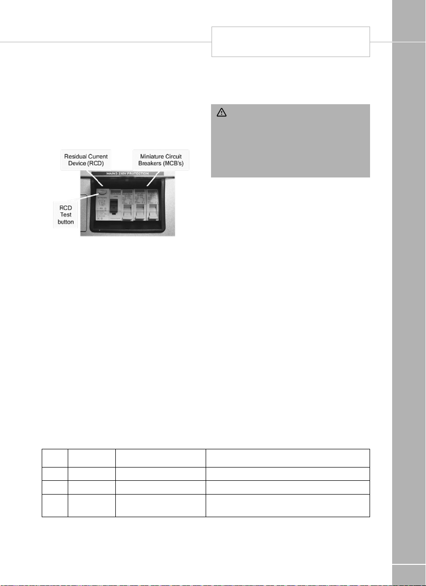
SWIFT COMMAND
POWER CONTROL SYSTEM
ELECTRICAL SYSTEMS
3. System Technical Information
The following section provides further technical
information relating to the electrical system.
You can also access the supporting technical
manual from www.sargentltd.co.uk
3.1 Residual Current Device & Miniature
Circuit Breakers
The Residual Current Device (RCD) is basically
provided to protect the user from lethal electric
shock. The RCD will turn o (trip) if the current
owing in the live conductor does not fully
return down the neutral conductor, i.e. some
current is passing through a person down to
earth or through a faulty appliance.
To ensure the RCD is working correctly, the
test button should be operated each time the
vehicle is connected to the mains supply (see
section 2.3)
The Miniature Circuit Breakers (MCB’s) operate
in a similar way to traditional fuses and are
provided to protect the wiring installation from
overload or short circuit. If an overload occurs
the MCB will switch o the supply. If this occurs
you should investigate the cause of the fault
before switching the MCB back on.
The following table shows the rating and circuit
allocation for the three MCB’s
3.2 Battery Charger
Caution should be used before connecting a
generator to your motorhome.
WARNING: Never start or stop the
generator while electrical loads are
connected and switched on. Start the
engine, let it stabilise and then connect the
electrical load. When stopping the generator,
disconnect the electrical load and let engine
stabilise before switching o.
Whilst some generators use electronic inverter
technology, others use a more basic principle
to generate the 230V supply. Preference should
be to choose a generator which produces a
consistent sinusoidal wave form with accurate
voltage control.
The Reverse Polarity warning light on the PSU
may illuminate when using a Generator. This is
a normal side eect when using some types
of generator. Instead of connecting the neutral
conductor to earth, some generators centre
tap the earth connection making both neutral
and live conductors 110V above earth. This
110V dierence causes the neon polarity
indicator to illuminate.
In most cases it is safe to use a generator, but
please consult the generator handbook for
further information.
MCB Rating Output Wire Colour Description
1 10 Amps White 230V Sockets
2 16 Amps White (Yellow for heater) Extra 230V Sockets / Heating System
3 10 Amps Black (Blue for Whale
water heater)
Fridge / Charger / Auxiliary devices / Whale
Water Heater
81

SWIFT COMMAND
POWER CONTROL SYSTEM
3.3 Battery Charger
The system incorporates an intelligent threestage battery charger.
ELECTRICS
During stage 1 the battery voltage is increased
gradually while the current is limited to start the
charging process and protect the battery. At
stage 2 the voltage rises to 14.4V to deliver the
bulk charge to the battery. When the battery
is charged, the voltage is decreased at stage
3 to 13.6V to deliver a oat charge to maintain
the battery in the fully charged state. The
charger can be left switched on continuously
as required.
The battery charger / power converter also
provides power to the leisure equipment when
the mains supply is connected. This module
supplies DC to the leisure equipment up to a
maximum of 25 Amps (300 Watts), therefore
the available power is distributed between the
leisure load and the battery, with the leisure
Leisure
Load
10A 15A
15A 10A
20A 5A
Available power for battery
charging
5A 20A
3.4 Leisure Battery
A) Type / Selection
For optimum performance and safety it is
essential that only a proprietary brand LEISURE
battery is used and it is suggested to select a
battery from the NCC Veried Battery Scheme
with a typical capacity of 75 to 120 Ah (Ampere/
hours). Depending on the prospective use of
the vehicle the correct type should be selected
(A, B or C). A normal car battery is NOT suitable.
This battery should always be connected when
the system is in use.
The PSU is congured to work with standard
lead acid leisure batteries, and in most cases
is also compatible with the latest range of
Absorbed Glass Matt (AGM) batteries. The
system is also suitable for Lithium batteries with
built-in Battery Management Systems BMS).
Before tting non-standard batteries please
check that the charging prole described in 3.3
is suitable for the type of battery by referring
to the battery documentation or battery
manufacturer.
Some vehicle installations can cater for two
leisure batteries connected in parallel. In these
cases it is recommended that two identical
batteries are used.
The battery feed is tted with an inline fuse
between the battery and the electrical harness,
and is usually located immediately outside the
battery compartment or within 500mm of the
battery. The maximum rating of this fuse is
20A per battery. If a single battery is tted to
a motorhome, this fuse could be up to 40A,
however if two batteries are tted each battery
should be fused at a maximum of 20A.
82
WARNING: Under heavy loads the Battery
Charger case may become hot. ALWAYS
ensure the ventilation slots have a clear ow
of air. Do not place combustible materials
against / adjacent to the charger.

SWIFT COMMAND
POWER CONTROL SYSTEM
ELECTRICAL SYSTEMS
B) Installation & Removal
Always disconnect the 230V mains supply
and turn the PSU green charger switch to the
o position (button out) before removing or
installing the battery.
When connecting the battery, ensure that the
correct polarity is observed (black is negative
[-] and red is positive [+]) and that the terminals
are securely fastened. Crocodile clips must not
be used.
WARNING: Explosive gases may be
present at the battery. Take care to prevent
ames and sparks in the vicinity of the battery
and do not smoke.
Battery Voltage
cut o
Vehicle 10.9V Battery selection is
Leisure 9V Power is turned o This is an emergency cut o level to
Action after
cut o
changed from Vehicle
battery to Leisure
battery. If the leisure
battery is below 9V then
a further warning will
occur (see below).
C) Operation / Servicing
Under normal circumstances it should not be
necessary to remove the battery other than for
routine inspection of the terminals and “topping
up” of the battery uid where applicable. Please
see instructions supplied with the battery.
Note: Do not over discharge the battery. One
of the most common causes of battery failure
is when the battery is discharged below the
recommended level of approximately 10V.
Discharging a battery below this gure can
cause permanent damage to one or more of
the cells within the battery.
To prevent over discharge, the power control
system incorporates a battery protect circuit
that warns the users and then disconnects the
batteries when they fall below set values.
If a warning is active a beep will be emitted by
the control panel and information will be shown
on the screen. To cancel the warning, press
the select button. These warnings will not be
repeated unless the power switch is turned
o and on again. This is to ensure the warning
does not become a nuisance.
Notes
This cut o level is designed to protect the
vehicle battery from over discharge. The
10.9V level ensures there is sucient power
in the battery to run the vehicle electronics
and start the vehicle. This cut o only
applies to power drawn from the battery
by theleisure equipment; it will not protect
thebattery if you leave vehicle circuits
switched on, such as the road lights.
protect the battery from severe damage.
You should not rely on this cut o level
during normal operation, but manage your
power consumption to a discharge level
of about 11.5V. This cut o only applies to
power drawn from the battery by the leisure
equipment that is controlled by the control
panel power switch; it will not protect the
battery from discharge by permanently
connected equipment.
83

ELECTRICAL SYSTEMS
SWIFT COMMAND
POWER CONTROL SYSTEM
3.5 12 Volt DC Fuses
WARNING: When replacing fuses
always replace a fuse with the correct value.
NEVER replace with a higher value / rating
as this could damage the wiring harness.
If a replacement fuse ‘blows’ do not keep
replacing the fuse as you could damage the
wiring harness. Please investigate the fault
and contact your dealer.
The following table shows the fuse allocation for the 13 fuses tted to the PSU. Please note that
fuses are dependant on PSU versions, so not all fuses may be present.
Fuse Rating Fuse
Colour
1 25 Amps White Charger
2 7.5 Amps Brown Permanent 12V / Alarm / Fridge Electronics
3 10 Amps Red 12V Sockets / TV Amplier
4 10 Amps Red Extractor Fans
5 5 Amps Tan Appliances / Hob Ignition / Toilet
6 10 Amps Red Water Pumps / Tank Heaters
7 7.5 Amps Brown Lighting, Main Lights & Dim Channel 1
8 7.5 Amps Brown Lighting, Entry Light & Dim Channel 2
9 10 Amps Red Truma Heating / Marker Lights / En-Route Sockets & Lights
10 10 Amps Red Auxiliary / Awning Light / Electric Step
11 20 Amps Yellow Fridge 12V
12 15 Amps Blue Towing 12V
13 15 Amps Blue Fridge D+
Description
84
Note: Fuses (2-13) have a Red LED below
them which provides indication that the fuse
has blown. The charger fuse has a green LED
which Indicates that the charger is working.
Fuse Rating Fuse
Colour
Battery 1 40 Amps Orange Fuse remotely located near battery
Battery 2 40 Amps Orange Fuse remotely located near battery 2 (where tted)
Description

SWIFT COMMAND
POWER CONTROL SYSTEM
3.6 Common Fault Table
Fault Possible Cause Proposed Fix
ELECTRICAL SYSTEMS
No 230 volt
output from
PSU
Reverse
Polarity light is
illuminated on
PSU
Connecting lead between the site
and Leisure Vehicle not connected
RCD switched o Reset RCD as per 2.3D
RCD not operating correctly Check supply polarity; if the RCD
MCB switched o Reset MCB by switching OFF (down
No or decient supply from site Contact site Warden for assistance.
Other fault Contact your Dealer
Mains Supply reversed? The reverse polarity light is designed
Generator being used ‘The Reverse Polarity warning light is on
Check and connect lead as per 2.3C
continues to fail contact your Dealer as
there is probably an equipment or wiring
fault.
position) then back ON (up position),
if the MCB continues to fail contact
your Dealer as there is probably an
equipment or wiringfault.
to illuminate when the Live and Neutral
supply has been reversed / crossed
over. If the light illuminates there is a
problem with the site supply or the cable
connecting the supply to your vehicle.
The light is designed to work on UK
electrical supplies (where the neutral
conductor is connected to earth at the
sub station). If you are using your vehicle
outside the UK this light may illuminate
when no fault exists. In these cases
consult the site warden for advice.
when using my Generator’.
This is a normal side eect when using
some types of generator. Instead of
connecting the neutral conductor to
earth, some generators centre tap the
earth connection making both neutral
and live conductors 110V above earth.
This 110V dierence causes the neon
polarity indicator to illuminate. In most
cases it is still safe to use the generator,
but please consult the generator
handbook for further information.
85

SWIFT COMMAND
POWER CONTROL SYSTEM
Fault Possible Cause Proposed Fix
ELECTRICAL SYSTEMS
Control Panel
Problems
No 12 volt
output from
PSU
Control Panel has no display Check batteries and fuses, turn PSU
12V Power turns o Battery protect feature has operated to
Control Panel locked / erratic
function
No 230V supply Check all above
Charger not switched on Turn charger switch on, switch will
Battery not connected and / or
charged
Power button on control panel not
switched to on
Battery at / Battery fuse blown Recharge battery, check fuses, check
Fuse blown Check all fuses are intact and the correct
Equipment switched o /
unplugged
Other fault Contact your Dealer
isolate switch and charger switch on and
ensure mains supply is connected.
Check control panel connecting lead at
PSU and behind Control Panel.
Contact your Dealer.
protect the Vehicle battery and or the
Leisure battery. See 3.4C
Over voltage protection has been
activated, the control panel will display a
warning. A number of things can cause
this but the most common is the solar
panel, it is worth checking the regulator
is connected correctly and operating
within the correct parameters.
Engine has been started, all equipment
has been disconnected to meet EMC
requirements. See 2.4
Observe control panel handling
instructions. Control panel software may
have crashed. Reboot control panel by
turning o the PSU isolate switch. Wait
30 seconds then turn the switch back
on. Check with your dealer that your
system has the latest software installed,
as an update may be available.
illuminate
Install charged battery as per 3.4
Turn power on at control panel
charging voltage is present at battery.
value fuse is installed as per fuse table.
Check equipment is switched on and
connected to the 12V supply
86

SWIFT COMMAND
POWER CONTROL SYSTEM
Fault Possible Cause Proposed Fix
ELECTRICAL SYSTEMS
Fuse blown Replace fuse with correct value as per
Pump not
working
Comms not
working
Comms not
working
3.7 Contact details
Sargent Electrical Services Limited provide a
technical help line during oce hours. Please
contact 01482 678981 if you require technical
help.
For out of hour support please refer to the
support section of the Sargent web site
www.sargentltd.co.uk
Pump turned o Turn pump on by pressing the pump
Fuse/s blown Replace fuse with correct value as per
Lights turned o Turn Lights on by pressing the lights
Bluetooth not paired Using System Settings menu, select
Bluetooth not active on Device Ensure that the handheld device
Bluetooth out of range Ensure the handheld device is within 7M
fuse table
button at the control panel
fuse table.
button, use dimmer at the control panel.
Bluetooth Pair option
has Bluetooth switched on and that
the device supports the Bluetooth 4
standard (BLE)
of the middle of the motorhome
87

SWIFT COMMAND
POWER CONTROL SYSTEM
ELECTRICAL SYSTEMS
4 Remote Access & Control
4.1 Swift Command App
The Swift Command app can be down loaded
from the Apple App Store or the Android Play
store.
A separate Swift Command User Guide is
available which covers the operation of the app.
Before you can use the App with your
motorhome you will need to create an account
and sign up to the free communication service.
This is a simple process and will be explained
further by your dealer at the vehicle handover.
Additional information is available at
www.swiftcommand.co.uk
4.2 Swift Command Web usage & Description
In addition to the mobile App, you can also use
the same account and login details to access
the Swift Command web site.
Here you can update and amend your details,
look at location information and history, review
system information and historical data as well
as changing some system options and settings.
4.3 Swift Command SIM Coverage & Usage
information
The EC600 system contains Mobile SIM with
36 month contract, which commences upon
activation at the Dealership when your vehicle
is linked to your account.
Below is a list of the countries covered by the
SIM under a fair usage policy, a complete list is
available at request.
Austria, Belgium, Bulgaria, Cyprus, Czech
Republic, Denmark, Estonia, Finland, France,
Germany, Greece, Hungary, Iceland, Ireland,
Italy, Latvia, Liechtenstein, Lithuania,
Luxembourg, Netherlands, Malta, Norway,
Poland, Portugal, Romania, Slovakia, Slovenia,
Spain, Sweden, United Kingdom.
For vehicles shipping direct to Australia or New
Zealand a special world-wide SIM is tted at the
Swift factory.
Please note that if a UK specication vehicle is
shipped to these countries the remote features
will not operate.
4.4 Replacement parts
The Control panel contains a small lithium
battery to maintain the clock when no other
energy supplies are available this will last in
excess of 5 years under normal conditions. The
battery is a CR2032 3.0V
The EC630 Communication module contains a
special backup battery pack which should last
in excess of 3 years under normal conditions.
The pack part number is 16308 available from
Sargent.
4.5 Updates
From time to time there may be updates to the
system rmware; these updates will be done at
service intervals by your dealership.
88

SWIFT COMMAND
POWER CONTROL SYSTEM
5 Technical Data & Approvals
5.1 Equipment – EC652, EC653, EC800,
EC635 & PX300
Outline Specication
INPUT 230V 230 Volts / 0 to 16 Amps + / - 10%
RCD protected, 2 x MCB outputs of 10A & 1 x MCB
OUTPUT 230V
INPUT 12V 2 x 20A battery inputs via 2 x 4 way connectors
SOLAR INPUT
OUTPUT 12V
Integrated
CHARGER
Signal INPUT
Data IN / OUT
IP rating IP31
Operating
temperature
Dimensions
EC601, EC602,
EC652 &
EC653 PSU
EC800 Control
Panel
EC635 Comms
Module
EC840 Sensor Overall size (HxWxD) 20 x 35 x 38mm Weight 10g
output of 16A
Separate switched channels for heating system
and charger
1 X Dedicated solar panel input capable of
supporting 10A of solar power input (typically 180
to 200W) via a 2 way connector
25A total output via multiple switched channels
protected by 13 fused outputs
Input 220-240 Volts AC +/- 10%, Frequency 50 Hz
+/- 6%, Current 3A max.
DC Output 13.6 to 14.4 Volts nominal, Current 25
Amps max (300 Watts).
4 x Fresh water level, 4 x Waste water level, 1 x
Engine running, plus multiple vehicle connections,
sensor inputs for temperature & humidity
CANBUS Data communication and power to
Control Panel via 6 way connector CI-Bus Data
communication to CI-Bus enabled devices via
RJ11/12 connector
Ambient 0 to 35° Celsius Charger case temperature
with full load 65° C Max
Overall size (HxWxD) 180 x 305 x 135mm
Clearances 75mm above, 50mm left & right
Overall size (HxWxD) 125 x 279 x 25mm Cut-out
size (HxW) 108 x 173mm + switch area
Overall size (HxWxD) 55 x 116 x 85mm Weight 550g
Turn pump on by
pressing the pump
button at the control
panel
Check the solar panel
rating plate to ensure
the maximum current is
<= 10A
Fresh water negative
sensed Waste water
negative sensed
Automatic shutdown
and restart if
overheated /
overloaded
Weight 3.8 Kg
Fixing centres 250mm
X 74mm Weight 380g
ELECTRICAL SYSTEMS
89

ELECTRICAL SYSTEMS
SWIFT COMMAND
POWER CONTROL SYSTEM
5.2 Approvals
System: BSEN 1648-1, BSEN1648-2
compliant, BS7671: 2008 compliant
Residual Current Device: RCD 40A 30mA trip
to BS EN 61008
Miniature Circuit Breakers: MCB’s type C
6000A breaking capacity to BSEN 60898
Electro Magnetic Compatibility (EMC)
directive: 2004/108/EC Certicate
CE20071224-1
Integrated Charger: BS EN 60335-1/2.29,
2006/95EC, IEC61000-3.2/3:1995, 1.
Low Voltage Directive: 2006/95EC TUV014900-A1, EN55022, Class B, EN55024/
Level 2
5.3 Declaration of Conformity
Equipment: Leisure Power Control System
Model name: EC652, EC653, EC800, EC635
& PX300
I hereby declare that the equipment named
above has been designed to comply with the
relevant sections of the above referenced
approvals. The unit complies with all essential
requirements of the Directives.
90
Signed Name Position Manufacturer
I L Sargent Technical Director Sargent Electrical Services Ltd
Unit 35, Tokenspire Business
Park Woodmansey, Beverley East
Yorkshire, United Kingdom
Whilst every eort has been made to ensure
the accuracy and completeness of this
document, no guarantee is given against
errors or omissions. This document may be
updated / improved orver time therefore please
check with your dealer / supplier for update
information or visit www.sargentltd.co.uk

MOTORHOME BATTERY
ELECTRICAL SYSTEMS
Cab Radio - Timer Settings
On all vehicles tted with a Fiat entertainment
system, the amount of time the entertainment
system will stay ON, after the ignition is
switched OFF, can be adjusted. To adjust the
setting please follow the relevant method
below:
Fiat U-Connect Radio 3.0 (without satellite
navigation)
• Switch on Radio
• Press MENU to access the menu
• Turn Right hand dial and select SYSTEM
SETTINGS
• Turn right hand dial to select POWER OFF
180MIN DELAY
• Press right hand dial to select (tick box lls)
• Press BACK to exit menu system
Fiat U-Connect Radio Nav 5.0 (With satellite
navigation)
• Press SETTINGS which is the top right
button (symbol of two gear wheels)
• Using the dial to the right of the display, scroll
to VEHICLE OFF OPTIONS
• Select RADIO OFF DELAY using either the
touch screen or the right hand dial
• Choose the 180 MIN setting (alternative is 0
MIN) using the touch screen
• Press DONE on the touch screen, and exit
the menu system
For further details of the features within the Fiat
entertainment systems, please follow the links
below, or see the paper copy supplied with the
vehicle.
Fiat U-Connect Radio 3.0
(without satellite navigation)
http://aftersales.at.com/eLumData/
EN/77/290_DUCATO/77_290_
DUCATO_530.07.530_EN_01_03.14_SI_
UCR5/77_290_DUCATO_530.07.530_
EN_01_03.14_SI_UCR5.pdf
Fiat U-Connect Radio Nav 5.0
(with satellite navigation)
http://aftersales.at.com/eLumData/
EN/77/290_DUCATO/77_290_
DUCATO_530.08.170_EN_01_07.14_SI_
UCRN5/77_290_DUCATO_530.08.170_
EN_01_07.14_SI_UCRN5.pdf
If you are unable to view the documents on line,
please contact the supplier, your dealer or Swift
for an electronic or paper copy.
Motorhome Radio Aerials
Your Motorhome is tted with a base vehicle
aerial located in the passenger wing mirror. Any
issues with radio reception should be referred
back to your Fiat dealer.
Note: Some customers may wish to t an
aftermarket radio unit to the base vehicle.
While this is possible customers should note
this may aect steering wheel-mounted
controls and increase power consumption.
91

SOLAR PANEL
ELECTRICAL SYSTEMS
Factory tted Solar Energy System
Depending on specication, your motorhome
may be tted with a solar panel and regulator.
This solar panel and regulator may provide
additional 12V power whenever sunlight is
available to the panel, and this will be directed
to the Power Supply unit (PSU), whether the
control panel above the entrance door is ON
or OFF. Conditions allowing, the system then
keeps the battery/batteries ‘topped up’ during
storage, and can provide a daily boost to the
leisure battery when camping without a mains
230V supply.
If the system shutdown button on the PSU
is ON, then via the Smart Charging facility in
the PSU, charge may be directed to either the
leisure battery or vehicle battery, as required
and dependent on whether the vehicle battery
is isolated.
If the system shutdown button is OFF, charge
will be directed to the vehicle battery only.
Battery power
As a guide, a 40w panel is capable of supplying
up to 2.3 amps, +/-1.5%, while an 80w panel is
capable of supplying up 4.68 amps +/- 1.5%.
Depending on the state of the charge of the
battery it may take a few hours to several days
to recover a discharged battery. For obvious
reasons the solar panel will only work during
daylight hours.
Regulator operation
There are two LED indicators located on the
solar regulator. The rst is the ‘power’ LED and
this ashes when the solar panel produces
energy, the ash rate increasing with the
amount of sun light on the solar panel, until the
LED is on solidly. The second LED
is bicoloured, and it will indicated the charge
condition when sucient energy is being
received by the solar panel. If the second LED
is illuminated red, then the regulator is in bulk
charge mode supplying 14v plus, if the LED is
illuminated green then the regulator is in oat
charge mode supplying 13.6v.
Maintenance and cleaning
The solar panel will require cleaning periodically
in order to maintain the performance of the
panel, a caravan, car shampoo or simple soap
can be used; no abrasive cleaners should be
used.
92
Note: If additional solar panels are tted
and linked to the factory tted panel, the
maximum combined wattage must not
exceed 150W.

EQUIPMENT DETAILS
Truma Combination Boiler 94
Dometic Absorption refrigerator 100
Dometic minigrill 101
Dometic hob & bowl 102
Thetford oven 105
Thetford toilet 109
Window / Rollerblind advice 109
Roof lights 110
Seat swivel 111
Omnistep slide out step 112
Omnistor awning 108
Status 570 direction television and FM radio antenna 114
Care of laminate tops, tables, furniture and doors 115
Furniture doors 115
Table storage 115
Shower 115
Trigger Shower head 115
Colour reference 116
Door Flyscreen 116
FITTED EQUIPMENT
93

TRUMA COMBINATION BOILER
Note: The instructions covering tted
equipment to your motorhome were correct
at the time of going to print, and where
possible, hyperlinks and QR codes have been
used, which provide links
to online versions of user instructions.
Owners handbooks are updated annually
and we take great care to try and ensure
FITTED EQUIPMENT
their accuracy. However, the Swift Group
Limited cannot accept responsibility for any
changes that may be made in specication
or operating instructions to the equipment
described in this section after the time of
going to press.
Every care is taken to ensure that the
information provided in this handbook is
correct and easy to understand.
Separate manufacturers’ leaets on many of
the components are also included in the
Owner’s Pack provided with this motorhome
and we recommend that you compare the
instructions provided via the handbook with
the component manufacturers literature,
to ensure the information provided is as
accurate as possible.
If you are in any doubt as to how to operate
the equipment in your caravan, please
contact the component manufacturer’s
service department on the telephone number
shown on their component leaet. If you
remain in any doubt, please contact your
supplying dealer.
Notice: In the interest of safety, replacement
parts for an appliance shall conform to the
appliance manufacturer’s specications and
should be tted by them or their authorised
agents.
Equipment Specication
For details on type of equipment tted in your
vehicle, please refer to the Sales Brochure or
Dealer.
WARNING: To maximise the use and
life of all tted equipment in your vehicle
it is essential that any accompanying
manufacturers’ literature is read fully. All
recommended maintenance and preparation
procedures should be followed. The
information provided in this handbook is
only intended as a guide. If in any doubt
consult your manufacturer appointed dealer,
particularly before attempting to install
EXTRA EQUIPMENT.
Truma Combination Boiler
The Truma Combination Boiler can be used in
the following ways:
To provide combined room heating and water
heating.
• Simultaneous heating of the room, and
water contained within the appliance. Often
referred to as Winter Mode.
To provide water heating only.
• Heating of the water within the appliance,
without room heating. Often referred to as
Summer Mode.
To provide room heating only, without water
heating.
• If the water system has not been primed,
meaning that there is no water within the
appliance, it is still possible to use the
Combination Boiler to heat the room.
94

ALDE HEAT EXCHANGER
FITTED EQUIPMENT
Dual Fuel operation
The Truma Combination boiler has been
designed to run on gas or electric power, and
the optimum performance is obtained when
used in dual fuel mode, that is running on gas
and electric at the same time.
Running in dual mode has the following
benets:
• The fastest possible heat up time, as the gas
burner combines with an electric element to
provide energy to heat your hot water and
warm your caravan.
• The intelligent heat management system
automatically senses when the water and
room are nearing the required temperature
and then automatically turns o your gas
burner and operates solely on electric power,
conserving your gas.
• As hot water is used or the room cools the
Truma combination heater will continue to
operate on electric only, until a point where
the demands necessitate that additional
gas power is also required. An example for
such a demand could be for instance if the
exterior door was left open and the room
temperature dropped by 10 degrees in the
space of a few minutes, in this case the
intelligent heat management system would
decide the best way to get the room back to
the required temperature, would be to use
both gas and electric at the same time.
Operating the Truma Combination system on
electric or gas only will result in longer heat up
times for hot water, and room temperature, in
comparison to operating on dual fuel.
Operating on electric only may not in all cases
maintain a comfortable room temperature
especially in colder conditions.
Whilst taking energy consumption and the
environment into account, consider using the
Combi in Summer mode (water heating only)
when room or space heating is not required, but
may be needed in the near future. This ensures
the appliance is held at the same temperature
as the hot water setting chosen, and this can
reduce the time taken to provide warm air into
the living area, when room or space heating is
then selected.
Truma Heating System and Air Flow
The Swift Group undertakes considerable
testing of our products in cold chambers
to ensure they meet the BS EN 1646
Grade 3 standard and are usable in cold
temperatures
95

TRUMA COMBINATION BOILER
Buttery outlets
The majority of air ducting outlets on models
equipped with Truma Combi heating systems,
are of the buttery type. These may be opened
or closed by moving the ap within the tting,
to adjust the balance of the heating output
throughout the caravan. This can help oset
FITTED EQUIPMENT
dierences in blown air output, between
outlets close to the heating appliance, and
those greater distance away from the heating
appliance. This can also help adjust the
temperature of the bathroom, relative to the
temperature of the main living area and/or
bedroom.
When these butteries are closed in
conjunction with a high heating system
output, and therefore a high fan speed, a slight
whistling sound can occur. In this case, opening
the outlet slightly will reduce or remove the
noise.
Closing too many outlets when the heating
system is producing a high output, can
cause the appliance to reach high operating
temperatures. This does not in general terms
eect the appliance, but can cause the
appliance to automatically shut down. This
can cause an interruption of the heating of the
motorhome, however heating will resume when
the appliance temperatures have reduced to a
lower level.
The output of the appliance, and therefore the
output of the blown air outlets, will generally be
higher when using Gas or Duel Fuel operation.
Electric only operation of the heating is rated
at up to 1.8kW , whereas Gas (or Dual Fuel)
operation is rated up to 4kW (3.8kW) or 6kW
(5.8kW), depending which model or Combi is
tted.
The blown air ttings can also be rotated to
adjust the direction of air leaving the outlet, as
shown in the photo.
96

DOMETIC OVEN
FITTED EQUIPMENT
Truma Combination Boiler Control Panel and
appliance instructions
Please read the user instructions before using
the heating system. The instructions include
warnings regarding the safe use of the system,
and no liability whatsoever can be accepted
for damage or injury resulting from failure to
observe the instructions.
The heating system can be controlled by a
Truma CP+ controller, or the Swift Command
control panel, App., or remote control system.
For Swift Command functions please see the
Swift Command literature and details within
this handbook.
For use of the CP Plus controller, and general
user instructions for the heating system
appliance, please read the Truma information
available at the following locations:
CP Plus Controller
https://www.truma.com/downloadcenter/ cp_
plus_installation_operating_de_gb_fr_ it.pdf
Combi 4 Gas/Electric and Combi 6 Gas/
Electric appliances
https://www.truma.com/downloadcenter/
combi_e_cp_plus_ready_operating_de_gb_
fr_it_nl_dk_se.pdf
If you are unable to view the documents on
line, please contact the supplier, your dealer or
Swift for an electronic or paper copy.
Electrical Operation of Truma Combination
Boiler
Before the heating system is used for heating
using electrical (230v) energy, the 230v
isolation button on the Sargent Power Supply
Unit must be switched ON, as shown in the
image below. To conrm a supply is available,
the button will be illuminated when a power
supply (mains hook up) is connected and the
button is ON.
Troubleshooting instructions (Combi heater)
In the event of a problem occurring, a warning
or error code will be displayed on the Truma
CP Plus control panel, along with a warning
triangle. Further warning information will also be
displayed on the Swift Command control panel.
The Truma combi boiler (heater and water) has
two styles of error code warnings which are
shown on the CP+ display panel. Depending
on the nature of the fault, the boiler will
require resetting in a slightly dierent manner,
depending on the fault.
• Solid error warning code
• Flashing error warning code
Before trying to reset any faults please check
that the 12v supply is on, and depending on
which energy source is going to be used for
heating, either mains electricity is available
and switched on, and/or that the gas bottle is
open and ready to dispense gas.
The following table on the next page describes
causes and remedies to the various fault codes
that may be displayed on the Truma control
panel.
Once the fault has been rectied the fault can
be reset via the control panel
97

TROUBLE SHOOTING GUIDE
(COMBI GAS HEATER)
SOLID CODE
Using the control dial on the cp+ panel scroll
down to the bottom line where the triangle
appears.
• Press this button to acknowledge the error
• The error code and triangle should disappear
if the fault has been rectied
FITTED EQUIPEMNT
FLASHING CODE
• Scroll round (as above) to acknowledge the
error on the panel
• Leave the panel UNTOUCHED for 15 minutes
– This allows the user to check that fuel
sources are available, and is a regulatory time
frame
Error
code
#17 Summer mode with empty
#18 Warm air temperature exceeded:
#21 Room temperature sensor
#24 Risk of low voltage. Battery
#29 Frost Control heating
#42 Open window above cowl
#43 Overvoltage > 16.4V Check battery voltage / voltage sources such as
#44 Low voltage. Battery voltage
Cause Remedy
water container
Not all warm air ducts are
connected
Circulated air intake blocked Remove the circulated air intake blockage
or cable faulty
voltage is too low < 10.4V
element has a short circuit
(window switch)
is too low <10.0V
• After 15 minutes the triangle will become solid
• The panel can be reset as per the above
process for SOLID
If the CP+ panel is reset 5 times, without the
fault being rectied the fault will become a
‘FLASHING’ CODE and will be locked for 15
minutes. If the control panel (cp+) is touched
within 15 minutes, the 15 minute ‘count’ will
restart. It is imperative that the panel is left
untouched during this time.
Truma Customer Service can be contacted on
01283 587960 or technical@trumauk.com if
you require further assistance
Switch heater o and allow to cool. Fill boiler with
water
Check whether the 4 warm air ducts are
connected
Inspect the room temperature sensor cable, replace
if faulty
Check the resisitance of the room temperature
sensor.
15°C - 16.2 kOhm / 20°C - 12,6 kOhm / 25°C
- 10.0 kOhm
Replace room temperature sensor if faulty
Charge battery
Disconnect heating element plug from electronic
control unit. Replace heating element
Clode window
the charger
Charge battery. If necessary replace old battery
98

TROUBLE SHOOTING GUIDE
(COMBI GAS HEATER)
FITTED EQUIPEMNT
Error
code
#45 No 230 V operating voltage Restore 230 V operating voltage
#112
#121
#122
#202
#211
#212
# 255 Heater has no 12 V power
# 301
# 417
# 401 Summer mode with empty
# 412 Open window above cowl
# 419 Overheating protection has
# 507 Gas cylinder empty Replacing a gas cylinder
# 514 The 12V supply has been
Cause Remedy
230 V fuse defective Replace 230 V fuse (see Combi operating
Overheating protection has
been triggered
Gas cylinder empty Replacing a gas cylinder
Gas cylinder or quick-acting
valve in the gas supply line
closed
Gas pressure regulation
system iced up
Butane content in the gas
cylinder too high
Combustion air infeed or
exhaust outlet is sealed
Gas pressure regulation
system faulty
supply
No connection between
heater and control panel
Risk of low voltage. Battery
voltage is too low < 10.4 V
water container
(window switch)
been triggered
interupted
instructions)
Reset overheating protection (see Combi
operating instructions)
Check gas supply and open valves
Use regulator heater (EisEx)
Use propane. Butane is unsuitable for heating,
particularly at temperatures lower than 10 °C.
Inspect openings for obstructions (slush, ice,
leaves, etc.) and remove any obstructions
Inspect / replace gas pressure regulation system
Ensure 12 V power supply
Make connection between heater and control panel
Charge battery
Switch heater o and allow to cool. Fill boiler with
water
Close windows
Reset overheating protection (see Combi operating
instructions)
(gas heating continues in Mix mode)
Ensure the control panel of caravan / motorhome is
switched on. Ensure charger is switched on and / or
battery is connected
99
 Loading...