


CREATING SMILES FOR LIFE
Swi Group
Owner’s Handbook
Basecamp
Issued July 2017

Luxury
you deserve
WHEREVER YOU ARE
Truma Aventa
Experience the ultimate comfort of Automatic Climate
Control (ACC) by upgrading your Swift caravan with the
Truma Aventa Air Conditioner.
Your vehicles heating system and the Truma Aventa work
perfectly together to keep you cosy in the winter and cool
in the summer.
Set your preferred temperature just once and let the ACC
system keep you in ultimate comfort.
www.trumauk.com
Upgrade to even more
comfort on the move
Duvalay luxury
sleeping bags
& portable toppers
Luxury mattresses &
beds for your home

Truma Aventa
Upgrade to even more
comfort on the move
Experience the ultimate comfort of Automatic Climate
Control (ACC) by upgrading your Swift caravan with the
Truma Aventa Air Conditioner.
Your vehicles heating system and the Truma Aventa work
perfectly together to keep you cosy in the winter and cool
in the summer.
Set your preferred temperature just once and let the ACC
system keep you in ultimate comfort.
www.trumauk.com
®
The only Swift Partner for Paint
and Upholstery Protection
The only
one with the
Lifetime
Guarantee
Paint Protection Upholstery and Carpet Protection
From the Makers of Diamondbrite
Diamondbrite Leisure
The ultimate Paint and Upholstery Protection
for your Swift Basecamp
Diamondbrite Leisure is a two-step protection system for
your Swift Basecamp with a Lifetime Guarantee*
1. EXTERIOR
• Nano-Ceramic Technology
• Fade Resistant
• Never Polish Again!
2. INTERIOR
• Easy to Clean
• Stain Resistant
• Lifetime Guarantee
HOW DOES IT WORK?
If your paintwork was
magnified it would
reveal small pores in
the surface.
You will also receive a complimentary After Care pack including the fabulous Waterless Wash, plus a range of other professional cleaning products.
Jewelultra Ltd. Diamondbrite House, Ewell Lane,
West Farleigh, MAIDSTONE. ME15 ONG.
Tel 01622 815679
Email diamondbrite@jewelultra.com
Road traffic dirt
gathers in the pores
and attacks
paintwork.
Your first Paint Protection
application cleanses and
3 41 2
fills pores in the vehicles
paintwork leaving a smooth
finish that cannot be
penetrated.
Your second application
bonds with the first to create
a hard protective skin. It
leaves a high lustre finish that
rain and dirt cannot penetrate.
®
www.jewelultra.com
MADE IN UK
*Lifetime Guarantee applies for the length of time that the purchaser owns the vehicle and is non-transferable.

INTRODUCTION
INTRODUCTION
Dear owner
Thank you for deciding to buy one of our
new caravans.
We are sure you will enjoy many happy hours
in it and we hope the information and hints in
this handbook will heighten your enjoyment.
The handbook has been designed to give
you a general guide to the care, use and
maintenance of your caravan. Whether you
are a new or an experienced caravanner the
hints will help to protect your investment.
The information contained will answer most
of your queries, but if there are any aspects
which are not covered please consult your
appointed dealer. We would suggest you
make a note of your dealers name and
contact information below.
Dealer Name:
Telephone Number:
Throughout the season, specifications and
equipment details contained within this
handbook may change. Please refer to our
online handbooks (www.swiftgroup.co.uk)
for the most up-to-date version of your
handbook.
Customers should note that there are two
handbooks, the User Handbook which
contains general information for the use
and care of your product and the Technical
Handbook, which contains technical
information, weights and dimensions of
your product.
First Service Due:
Dealer Contact Sales:
E-mail:
Serial Number:
Dealer Contact Parts:
Dealer Contact Service:
1

SWIFT TALK
CONTENTS
I chat on
Talk
t
wi
S
SwiftTalk
Social Network for Caravan and Motorhome enthusiasts
www.swift-talk.co.uk
f
Swift Talk
Swift Talk is the central forum for the Swift
community online. A place for all those united
in their love of caravanning, motorhomes,
holiday homes and touring in general, to share
their experiences, meet new friends and find
out a world of information on how to enjoy
their touring lifestyle.
The site is packed full of features that actively
encourage members, not only to liaise with the
Swift Group via the forums, but also interact
with each other through publishing their own
content, uploading and sharing photos and
video, and even posting their own blogs for the
community to follow.
Swift Talk is the first place to learn about new
product launches, events and Swift Group
news, it’s also the first place customers can
go to as a quick reference to frequently asked
questions or to actively take part in the forums;
providing valuable feedback on Swift Group
products and customer service.
2
The online community can even be used to
create your own groups, perfect for Owners’
Clubs, dealers and exhibitors to attract new
members, publicise and build awareness
for upcoming events, rallies and shows.
Anyone who owns, uses, or is thinking of
buying a Swift Group caravan, motorhome
or holiday home, or would just like to be part
of the growing Swift community is actively
encouraged to sign up, create their own
content, and start talking!
Just visit www.swift-talk.co.uk
and become part of a unique
online experience.

CONTENTS
Warranty .................................................................................................................................... 5
Towing code .............................................................................................................................. 8
Safety & security ...................................................................................................................... 32
Services .................................................................................................................................. 38
Electrics ................................................................................................................................... 58
Fitted equipment ..................................................................................................................... 90
Maintenance .......................................................................................................................... 112
Useful information .................................................................................................................. 148
Index ...................................................................................................................................... 155
CONTENTS
3

Back to main menu
WARRANTY INFORMATION
Supplier contacts ....................................................................................................................... 6
To view the warranty details for your vehicle please follow the link:
WARRANTY INFORMATION
5

Back to section menu
WARRANTY
Supplier contacts
A number of Swift Group suppliers manage their own Technical and Warranty related queries.
Where a customer has a question relating to a product manufactured by a company listed below,
we would advise that the first contact should be directly with them.
WARRANTY INFORMATION
Sargent Electrical Services
Unit 39, Tokenspire Business Park,
Beverley, East Yorkshire, HU17 0TB
Phone: 01482 678981
Fax: 01482 678987
E-mail: support@sargentltd.co.uk
AL-KO Kober Limited
South Warwickshire Business Park
Kineton Road, Southam,
Warwickshire, CV47 0AL
Fax: 01926 818562
Email: mail@al-ko.co.uk
Truma UK Ltd.
Park lane, Dove Valley Park,
South Derbyshire, DE65 5BG
Phone: 01283 586020
Fax: 01283 586029
technical@trumauk.com
Thetford Ltd.
Unit 6, Brookfields Way, Manvers,
Dearne Valley, Rotherham,
South Yorkshire, S63 5DL
Phone - 0844 997 1960
Fax - 0844 997 1961
Email - infogb@thetford.eu
Alde International (UK) Ltd
Huxley Close, Park Farm South,
Wellingborough, Northants, NN8 6AB
Phone: 01933 677765
Fax: 01933 674975
Email: info@alde.co.uk
Dometic (UK) Ltd
Dometic House, The Brewery,
Blandford St Mary, Dorset, DT11 9LS
Phone: 0844 626 0133
Email: technical@dometic.co.uk
Whale
2 Enterprise Road, Bangor,
Co. Down, Northern Ireland BT19 7TA
Phone: 0845 217 2933
Email: info@whalepumps.com
https://sargentltd.co.uk
http://www.al-ko.co.uk
https://www.truma.com/
uk/en/home/index.php
https://www.thetford-europe.com
www.alde.co.uk
https://www.dometic.com
/en-gb/uk
http://whalepumps.com/
home.aspx
6

Back to main menu
TOWING CODE
Caravan towing code .............................................................................................................. 8
Caravan terms ........................................................................................................................ 8
Towing vehicle terms .............................................................................................................. 10
Measurement of nose weight .................................................................................................. 10
Type of driving licence held ..................................................................................................... 11
Glossary & checklist ............................................................................................................... 11
Useful memory aid .................................................................................................................. 13
Preparing for the road ............................................................................................................. 14
Tyre Maintenance ................................................................................................................... 17
The Tyre Law .......................................................................................................................... 18
Hitching up for AK160 ............................................................................................................. 18
Pre tow check list ................................................................................................................... 20
13 Pin Socket ......................................................................................................................... 21
Towcar electrics ....................................................................................................................... 22
Breakaway Cables .................................................................................................................. 23
Mirrors .................................................................................................................................... 25
Moving off .............................................................................................................................. 25
Reversing ............................................................................................................................... 25
Speed limits ............................................................................................................................ 25
Caravan handling .................................................................................................................... 26
Motorway driving .................................................................................................................... 26
Spare wheel ........................................................................................................................... 26
Changing a wheel ................................................................................................................... 27
Wheel Bolt tightening .............................................................................................................. 27
Jacking points ........................................................................................................................ 27
Stopping on a hill .................................................................................................................... 28
Arrival on site .......................................................................................................................... 28
Exterior Door .......................................................................................................................... 29
TOWING CODE
7

TOWING CODE
Back to section menu
Caravan towing code
This Code of Practice contains
recommendations jointly reviewed and
agreed by the following organisations:
The National Caravan Council
TOWING CODE
The Caravan Club
The Camping and Caravanning Club
The Caravan Writers Guild
The Department for Transport
Scope of the Code
The Code applies to all trailer caravans of
maximum laden weight not exceeding 3500 kg
(7,700 lbs), overall width not exceeding 2.3m
(7ft 6in approximately) and overall length not
exceeding 7m (23ft approximately), excluding
the drawbar and coupling.
This is legally the maximum size of trailer
that can be towed by a motor vehicle with a
maximum gross weight of less than 3500 kg.
Caravan terms
Empty Weight
The empty weight of the caravan includes
all loose items supplied by Swift e.g. Electric
hook cable, kit bag, entrance step, portable
waste tank and central heating fluid
(where applicable).
Mass in Running Order:
The mass of the caravan equipped to the
caravan manufacturer, standard specification.
The MRO comprises the empty weight of the
caravan and includes an allowance for gas.
Note: The mass of the caravan in running
order contains provision for the masses
of liquids, gas etc. (see Mass in Running
Order in the Technical Handbook). Part
of this provision can also be utilised as
additional payload, if for example, you wish
to travel with no gas cylinders.
Maximum User Payload:
The maximum allowable weight to be put into
the caravan whilst it is being towed.
This is made up of the personal effects and the
optional equipment payloads.
The user payload is the difference between the
Maximum Technically Permissible Laden Mass
8
and the Mass in Running Order.
The Mass in Running Order + Personal Effects
+ Optional Equipment = Maximum Technical
Permissible Mass or MRO + PE + OE =
MTPLM
Personal Effects
Those items which a user can choose to carry
in a caravan.
Note: The Personal effects payload includes
an allowance of 20kg for a leisure battery.
Optional Equipment
Items made available by the manufacturer over
and above the standard specification of the
caravan for factory fitted options.
Maximum Technically Permissible Laden
Mass (Lower Limit):
The fully laden mass of the caravan in the
manufacturers standard specification which
is stated in the publications, technical
handbooks, brochures and weight plate and
used for car matching.
Maximum Technically Permissible Mass
(Upper Limit):
The mass takes into account specific
operating conditions including factors such as
the strength of materials, loading capacity of
tyres, etc.
Payload Definition
The method of calculating the Mass in Running
Order (MRO) and user payload figures are in
line with European Vehicle Directives.
Allowances for essential equipment is
now contained within the MRO of the
caravan and as per NCC code of Practise
(CoP) 304.
This includes the following;
LPG 1 x cylinder = 10kg
The MRO is calculated with the fresh water
tank empty.
Back to section menu
TOWING CODE
Note: If you travel with water in the fresh
water tank, the payload will be reduced
accordingly.
The leisure battery is considered to be
included in the personal effects and an
allowance of 20kg has been made for this.
Items fitted at the point of manufacturer (wheel
locks, hook-up cable, plastic steps, waste
containers, etc.) are included within the vehicle
MRO.
! WARNING: Under no circumstances
should the maximum technically permissible
laden mass (MTPLM) be exceeded.
Upgrading of maximum technically
permissible laden mass:
The lower (or standard) MTPLM is quoted in
the Technical Handbook, in brochures and on
the caravan weight plate. However, in some
cases it may be possible to increase this
to a higher (upper) MTPLM. (See Technical
Handbook for details).
If extra user payload is required, an upgrade
maybe available (model dependant), this
must be requested via your dealer and is
chargeable.
If required you will be issued with the following:
(i) New weight plate giving upgrade weight
details.
(ii) New NCC certificate (declaring the
upgraded MTPLM)
(iii) Manufacturers letter confirming the upgrade
for that Vehicle Identification Number.
Note: Tyre pressures may increase when
upgrading the MTPLM.
Nose weight:
The vertical weight transferred to the towing
vehicle through the coupling head.
Notes:
(i) When measuring the noseweight it is
important that the caravan is fully loaded.
Do not place extra items indiscriminately into
the caravan after this adjustment has been
made.
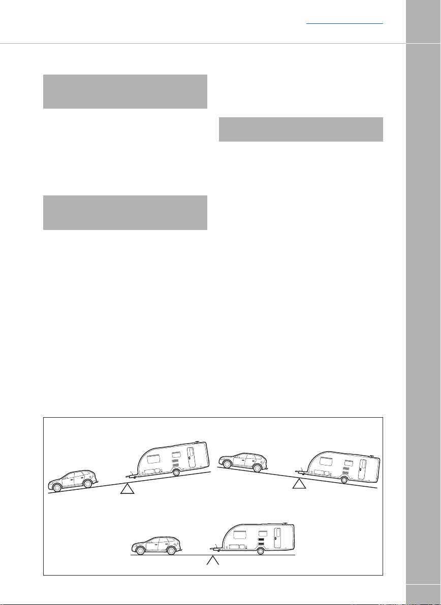
(ii) The caravan is intended to be towed
slightly nose heavy. The nose weight can
be adjusted by distribution of the load
within the caravan. The nose weight
should be approximately 5%-7% of the
actual laden weight (but not greater than
the hitch capacity) and at the same time
suit the towing vehicle. See section on
Measurement of Nose Weight.
(iii) It is not recommended that you tow with
just a battery, spare wheel and gas bottles
as this may exceed the permitted nose
weight. Additional payload must be placed
behind the axle to compensate for this.
Fig. A Car/Caravan
weight ratios
YES NO
85%
MAYBE
Equal
9

TOWING VEHICLE TERMS
Back to section menu
Towing vehicle terms
Kerb weight
(Mass of Vehicle in Running Order):
The weight of the towing vehicle as defined by
the vehicle manufacturer. This is normally with
TOWING CODE
a full tank of fuel, with an adequate supply of
liquids incidental to the vehicles propulsion,
without driver or passengers, without any load
except loose tools and equipment with which
the vehicle is normally provided and without
any towing bracket.
Caravan to Towing Vehicle Weight Ratio:
The towing vehicle to caravan weight ratio can
be determined by calculation and is equal to:
Actual laden weight of caravan
Kerb weight of towing vehicle
The law requires that caravans & their towing
vehicles & the loads they carry must be in
such a condition that no danger or nuisance
is caused.
(Regulation 100 of the Road and Vehicles
[Construction and Use] Regulations 1986).
Note: The towing vehicle manufacturer’s
limit is, in some cases, less than the kerb
weight.
Measurement of nose weight
Nose weight may be measured using a
propriety brand of nose weight indicator.
Such equipment is obtainable at your
Caravan Dealer.
Note: These indicators have a varying
tolerance level and may not be accurate.
Another simple method is to use bathroom
scales under the coupling head with a piece of
wood, fitted between the coupling head and
the scales, of such length that the caravan
floor is horizontal with the jockey wheel raised
clear of the ground. (Fig. A)
x 100%
LEVEL
430mm
±35mm
GROUND LINE
Fig. A Measuring nose weight
10
Mass in Running Order:
Caravanners can use a public weigh bridge to
establish the mass in running order.
Note: Weigh bridges have varying weight
tolerance levels.
Maximum Permissible Towing Mass:
The weight defined by the vehicle
manufacturer as being the maximum that the
vehicle is designed to tow at.
Train Weight (Combination Weight):
The maximum combined weight of the towing
vehicle and trailer combination as specified by
the towing vehicle manufacturer.
Nose weight can be adjusted simply by
distribution of weights in the caravan.
Always lower jockey wheel before entering
the caravan and then raise before measuring
again. (See Loading).
Note: The height of the towball on the
towing vehicle, when laden, is also critical.
! WARNING: Do not lift the coupling head
by hand when hitching the caravan to the
car. Always raise and lower the coupling
head by winding the handle on the jockey
wheel up and down.

Back to section menu
DRIVING LICENCE / GLOSSARY AND CHECKLIST
TOWING CODE
Driving licence
If you passed your car test before 1st January
1997 you are generally entitled to drive a
vehicle and trailer combination up to 8,250kg
maximum authorised mass (MAM). This is
the weight of a vehicle or trailer including the
maximum load that can be carried safely when
it’s being used on the road.
You can also drive a minibus with a trailer over
750kg MAM.
If you passed your driving test after 1st
January 1997 and have an ordinary category
B (car) licence, you can:
• Drive a vehicle up to 3,500kg MAM towing a
trailer of up to 750kg MAM
• Tow a trailer over 750kg MAM as long as
the combined MAM of the trailer and towing
vehicle is no more than 3,500kg
For anything heavier you need to take a
category B+E driving test.
From 19th January 2013, drivers passing a
category B (car) test can tow:
• Small trailers weighing no more than 750kg
• A trailer over 750kg as long as the combined
weight of the trailer and towing vehicle is no
more than 3,500kg MAM
If you want to tow a trailer weighing more
than 750kg, when the combined weight of
the towing vehicle and trailer is more than
3,500kg, you’ll have to pass a further test
and get B+E entitlement on your licence.
Glossary & checklist
Awnings - Can consist of just a simple top
sheet but may extend to a five sided frame
tent attached to the side of the caravan.
Fire blanket - approved to BS 6575 is ideal
for dealing with ‘fat pan’ fires.
Fire extinguisher - It is strongly
recommended that a fire extinguisher is carried
in the caravan. (For suitable types see Safety
and Security).
Gas bottles - Bottled L.P. gas is the most
convenient portable source of fuel. Ideally, two
bottles are required for a constant supply.
An initial deposit is payable on each cylinder.
We recommend the use of 6kg Calor Light
Propane bottles. One position for use and one
for storage only. (For detailed information see
Services - Gas).
Jack - A suitable jack is essential (screw,
scissor, side mounted or air jack type).
Many car jacks are unsuitable. Ensure the
lifting capacity of the jack is suitable for your
caravan.
Levellers - Levellers help level the caravan
from side to side before unhitching. Proprietary
products can be purchased from your caravan
dealer and need to be positioned as indicated
by a spirit level.
Spare Wheel - It is always advisable to carry
a spare wheel with your caravan.
Spirit Level - A spirit level is extremely useful
when siting the caravan.
Stabiliser - Stabilisers help to dampen the
side to side movement of the caravan.
Torque Wrench - A torque wrench is the only
way that the exact recommended torque can
be achieved for wheel nuts and bolts. (See
Preparing for the Road).
11

GLOSSARY AND CHECKLIST
Back to section menu
Towing Bracket - Never use cheap
alternatives, obtain one manufactured by
a reputable company complying with the
relevant standards.
Any light passenger vehicle registered in the
TOWING CODE
UK on or after August 1st 1998 will require a
type approved towbar and towball
(to 94/20/EC or UN ECE R55).
Failure to fit a homologated towbar and
towball could result in a prosecution and
invalidation of your insurance cover.
Always check with your car manufacturer or
towbar manufacturer if in doubt.
Wooden Blocks - Wooden blocks typically
25cm square and 2cm thick are ideal for
placing under corner steadies and jockey
wheel when the ground is uneven or soft.
Water Containers - Two containers are
required, one to carry fresh water to the
caravan and one for waste water, which needs
to be disposed of properly. Several types
are available including jerry cans, Aquarolls,
wastemaster, etc .
13 Pin Socket - One socket fitted to the
car to accept corresponding plugs from the
caravan this energises the road lights and
caravan auxiliary circuits.
12 Volt Battery - A deep cycling, heavy duty
rechargeable leisure type battery should be
purchased to provide back-up power for
lights and other electrical appliances. (See
Battery). The securing arrangements for the
battery compartment require a leisure battery
complying with EN 60095-2 in particular those
with ledges for fastening to the lower edge
of the long sides. The maximum battery size
that can be fitted is 225mm high, (including
terminals) x 175mm deep x 353mm wide.
The depth and width dimensions include the
rim around the bottom used for securing the
battery.
! WARNING: Your caravan dealer should
be consulted if additional equipment is to be
fitted as strong points may or may not be
provided in the design.
Caravan motor movers
The design and fitment of a caravan motor
mover shall be in accordance with the NCC
Code of Practice 305 and you should ensure
you receive a signed installation certificate of
compliance from the installer.
Failure to do so may invalidate your
warranty.
Note: Fitting additional equipment, such
as a motor mover will reduce the caravan
allowable payload.
Note: The fitting of a motor mover
may require a larger capacity battery fitting.
Note: If a towing cover is fitted, care should
be taken not to obscure lights, reflectors
and protect against rubbing or damaging
the bodywork.
12
Note: Check first that the battery will fit
within the battery box and can be secured
before purchasing.

Back to section menu
USEFUL ITEMS
TOWING CODE
Useful memory aid
Car
External mirrors
Fire extinguisher
Jack
Petrol can
Spare bulbs
Spare keys
Spare wheel
Tool kit
Towball cover
Tyre pressure gauge
Warning triangle
Tyre pump
Hi-Vis tabard(s)
Breathalyser kit (some Euro
countries)
Headlight stickers (Beam
deflectors)
Caravan
Awning pegs and poles
Awning ground sheet
Bucket
Corner steady brace
Corner steady pads
Coupling lock
Door mat
Fire blanket
Fire extinguisher
Fresh water container
Gas cylinders
Jack
Levelling boards
Mallet
Site/caravan mains lead
Spare bulbs (Mandatory in E.C.)
Spare 12v fuses
Spare high pressure gas hose
Spare wheel
Spirit level
Toilet fluid
Waste water container
Wheel brace
Personal
After sun cream
First Aid Kit
Flannels
Hairbrush and comb
Make up. etc.
Raincoats
Toothbrush
Toothpaste
Scissors
Shampoo
Shaving kit
Shoe cleaning kit
Soap
Sun tan oil
Wellington boots
Domestic
Adhesive tape
Air freshener
Aluminium foil
Ashtrays
Bedding
Bin liners
Binoculars
Bottle opener
Breadboard
Brush and dustpan
Butter dish
Camera
Carving knife
Chairs
Clock
Clothes brush
Clothes line
Coat hangers
Coolbox
Colander
Crockery
Cruet
Corkscrew
Cutlery
Dish cloth and brush
Dusters and polish
Disposable cloths
Egg cups
Floor cloth
Fly spray
Food
Food mixer
Frying pan
Glasses
Grill pan
Jugs
Kettle
Kitchen roll
Kitchen tools
Matches
Measuring jug
Milk jug
Mixing bowl
Needles and thread
Oven gloves
Pegs
Piezo Gas lighter
Potato peeler
Radio
Rubbish bin
Saucepans
Scissors
Sieve
Sugar bowl
Shopping bags
Sleeping bags
Tea pot
Tea strainer
Tea towels
Table cloths
Table mats
Television
Tin opener
Tissues
Toilet paper
Torch
Towels
Toys & Games
Vacuum cleaner
Washing up bowl
Documents
Bank and credit cards
Caravan Certificate
Cheque book
CRIS document
Driving licence
Green Card
Insurance (some Euro
countries)
Maps and guides
Money
MOT Certificate
Vehicle Registration
Documents
Gadgets
Mobile phone & charger
13
PREPARING FOR THE ROAD
Back to section menu
Preparing for the road
Pre-load checklist
! WARNING: Never enter the caravan
without first lowering the four corner
TOWING CODE
steadies with the brace provided.
Before loading check:
- loose articles are stowed securely.
Do not stow tins, bottles or heavy items in
overhead lockers prior to towing.
- all lockers and cupboard doors are closed
and secured, including the bathroom door.
- all bunks are secure.
- ensure shower door is secure
- all rooflights are closed and secured.
- main table is stored in its transit position.
- television aerial is lowered and locked
where applicable
- fridge is on 12V operation and door lock
is set.
- all windows and service doors are fully
closed and latched. Never tow with windows
on night setting. Leave all curtains and blinds
open to aid rear visibility.
- gas cylinders are correctly positioned,
secured and turned off, unless using en route
heating.
- battery is secure and mains connecting cable
is disconnected and stowed.
- Ensure control panel settings are correct
for 12v fridge operation. See control panel
instructions for detail.
- Exterior door is closed and locked
! WARNING: Always disconnect the
electrical connector between the towing
vehicle and the caravan before connecting a
LV supply to the caravan.
(a)
(b)
(c)
(d)
Fig. A Loading your caravan
14
! WARNING: Turn off gas appliances
except en route heating (if fitted).
! WARNING: Do not travel with televisions
or microwaves in overhead lockers unless
the appliance was supplied fitted to your
caravan by the manufacturer.
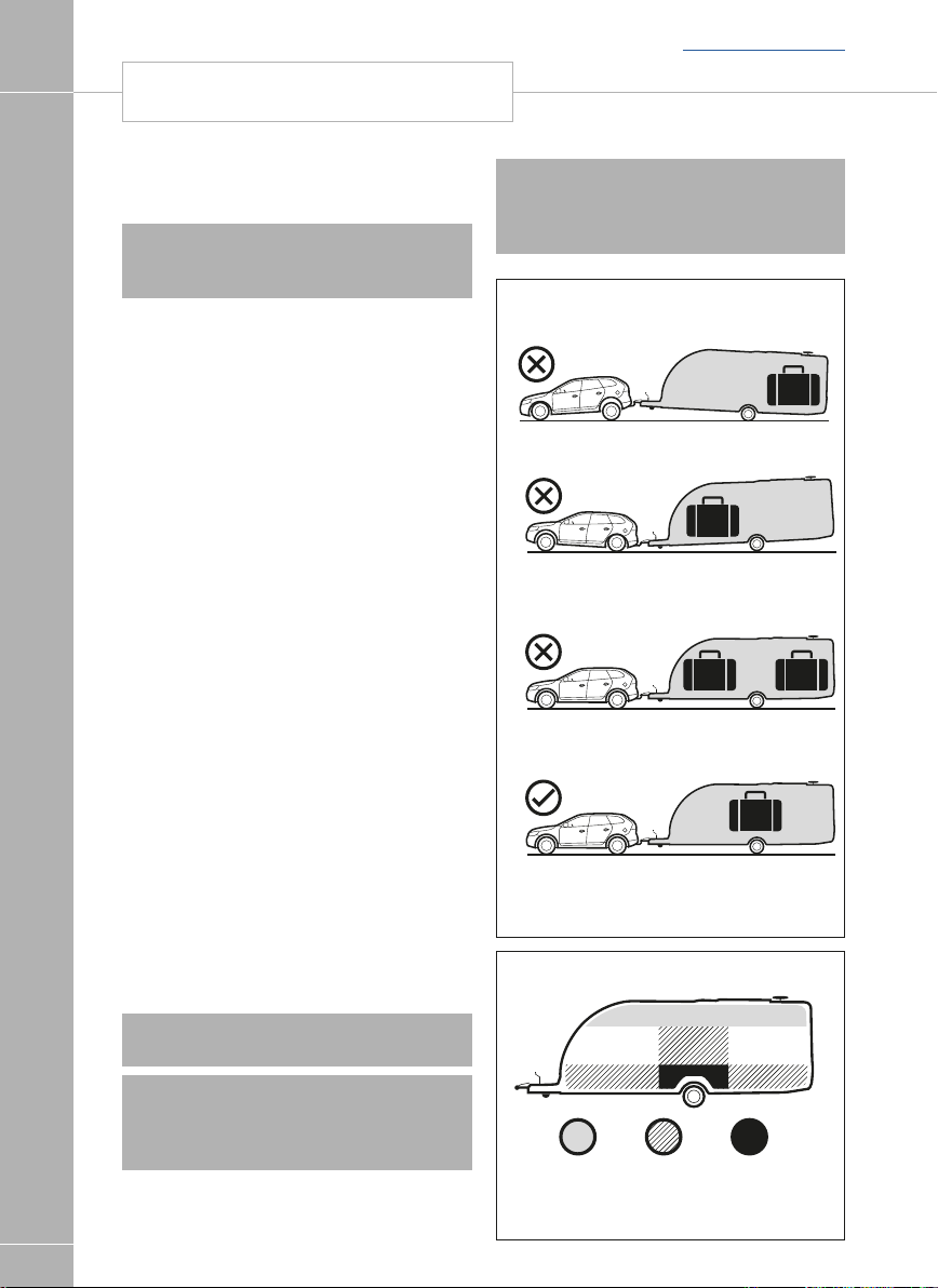
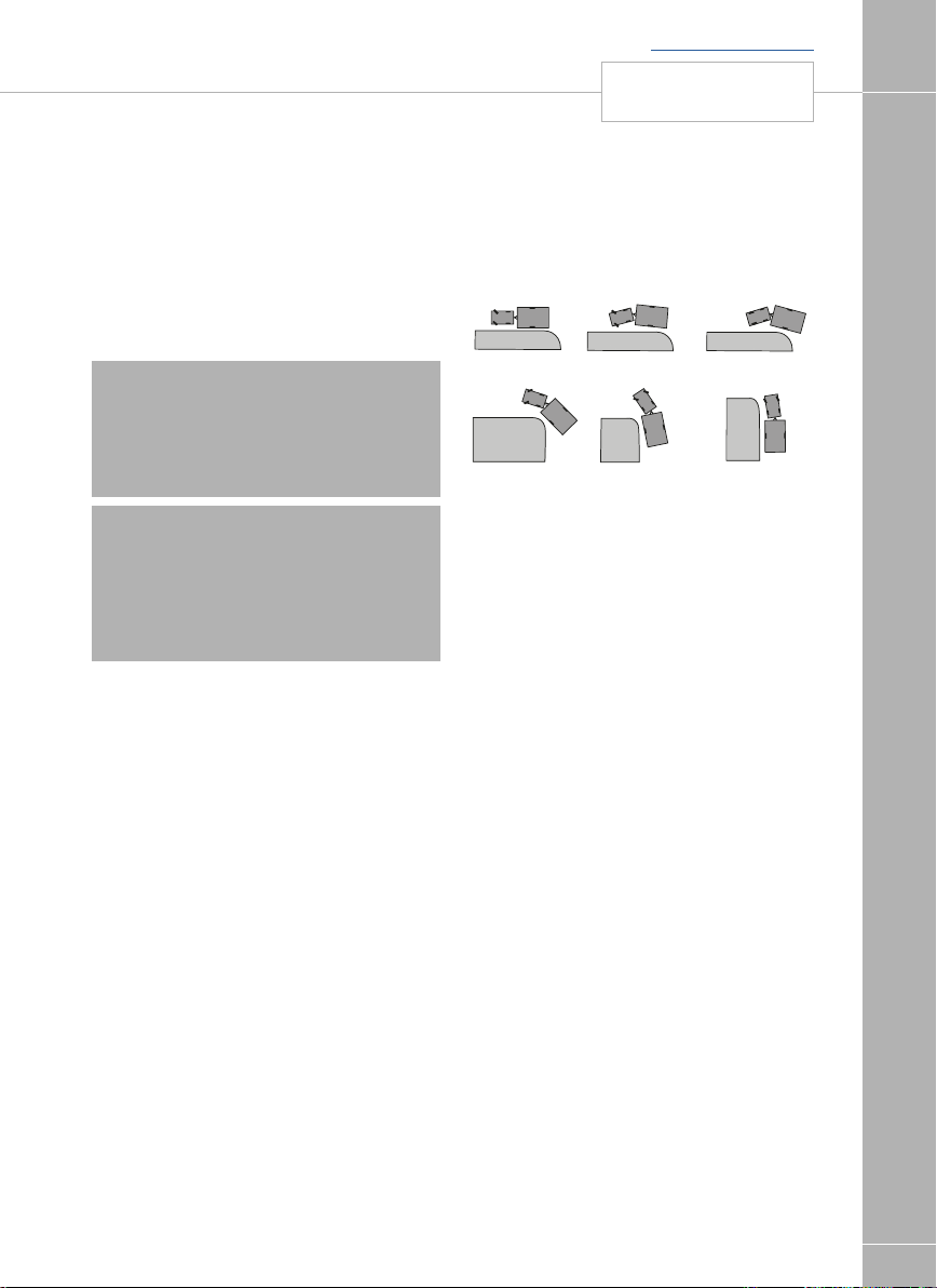
Light Medium Heavy
Fig. A Sensible loading
Back to section menu
TOWING CODE
How to apportion it
1. Load heavy items low down near the floor
and mainly over or just in front of the axle(s)
(Fig. A).
2. Load evenly right to left so that each
caravan wheel carries approximately the
same weight.
3. Do not load items at the extreme front or
rear since this can lead to instability due to
the ‘pendulum effect’.
4. Load remainder to give a suitable nose
weight at the towing coupling.
Check nose weight.
Note: Do not overload car boot.
! WARNING: All heavy and/or voluminous
items (e.g. TV, radio etc) must be stored
securely before travelling.
! WARNING: Please take care to
ensure that you have allowed for the
masses of all items you intend to carry
in the caravan. e.g. optional equipment,
and personal effects such as clothing, food,
pets, bicycles, sailboards, sports equipment
etc.
! WARNING: under no circumstances
should the MTPLM of this caravan be
exceeded
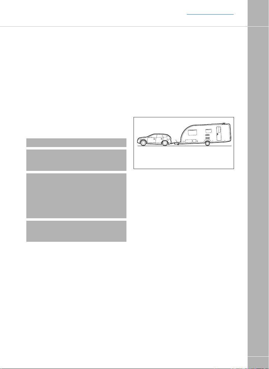
Towing vehicle’s rear suspension
It is important that the towing vehicle’s rear
suspension is not deflected excessively by the
nose weight on the tow ball. If it is excessive
the steering and stability will be affected.
(Fig. B)
The greater the towing vehicle’s tail overhang
(the distance between the rear axle and the
tow ball), the greater the effect the nose
weight will have on the towing vehicle’s rear
suspension.
Fig. B Illustration of excessive deflection
of vehicle’s rear suspension
After trying out the caravan it may be found
that a stiffening of the rear suspension is
necessary - but note that this may give the
towing vehicle a firmer ride when not towing.
There are a number of suspension aids
available and advice should be sought on
which to use and how to fit. It is important to
ensure that the caravan is towed either level or
slightly nose down.
If you have any doubts about the suitability of
your towbar for towing a caravan consult the
towing bracket manufacturer.
Do not exceed the:
• Gross Vehicle Mass (G.V.M. on car plate).
• Maximum Technically Permissible Laden
Mass (M.T.P.L.M.) on the caravan.
• Gross Vehicle Combination Mass (Train
Weight) (G.V.C.M. on car plate).
• Maximum Permissible Towing Mass.
• Vertical Static Load on the
caravan coupling (noseweight).
• Maximum Vertical Load on the car towball
as specified by towing vehicle manufacturer
(noseweight).
• Driving licence limitations
15

STABILITY
Back to section menu
Stability
All our models are of a well balanced design
and should be exceptionally good towers.
The common causes of poor stability include:
a. Worn springs or loose spring fixings on the
TOWING CODE
towing vehicle.
b. Towing vehicle springs too soft.
c Insufficient nose weight.
d Nose of caravan is towing too high or to low.
e Unsuitable towing vehicle.
Galvanised steel chassis
Drilling of the galvanised steel chassis will
invalidate the warranty and must not be done.
Suitable towing vehicles
The caravan is manufactured for towing behind
normal road cars and is not suitable for towing
behind commercial vehicles.
It is strongly recommended that whenever
a caravan is to be towed over rough terrain,
e.g. a field or track, great care should be
taken to ensure that no undue stress is placed
upon the caravan via the hitch mounting, i.e.
reduce speed. If in doubt, please consult the
chassis manufacturer and the towing vehicle
manufacturer who will advise.
Touring caravans based on standard AL-KO
chassis can be towed by four wheel drive off
road leisure vehicles providing the unit is used
to tow in a like manner to a conventional roadgoing car and driven in the same considered
manner.
Towbar manufacturers should be consulted
before towing an uncompensated twin axle
caravan.
Snaking
This is a term used to denote an unstable car
and caravan combination where the caravan
‘weaves’ from side to side often causing a
similar swaying movement in the car itself.
Causes:
1. Unsuitable or unbalanced outfit.
2. Incorrect loading or weight distribution.
3. Excessive speed especially downhill.
4. Side winds.
5. Overtaking.
6. Being overtaken by a large fast
moving vehicle.
7. Erratic driving.
8. Incorrect tyre pressures, car and caravan
9. Incorrect vehicle towball height
10. Worn hitch head or towball
Cures
Cases of persistent snaking can be alleviated
by the use of a stabiliser.
On the road
If you do find your outfit snaking, try to keep
the steering wheel in a central position as far
as possible, decelerate and avoid braking if
possible.
16

Back to section menu
TOWING CODE
Types of tyres fitted
The original tyres fitted by the manufacturer are
suitable for towing at a maximum speed of up
to 81 mph (130 kph).
Tyres
Caravan manufacturers choose the type,
size, profile, load carrying capacities and
speed ratings to match the design masses
of their vehicles, adjusting the tyre pressures
to suit. Only change the type of tyres on your
caravan on expert advice from the caravan
manufacturer, or tyre manufacturer.
Tyre maintenance
Tread depth
Pay special attention to the amount of tread
remaining on your tyres, and measure them
regularly. Always replace tyres before they
reach the minimum legal limit of 1.6mm.
Periodically tyres should be rotated to equalise
wear in the same manner as car tyres.
Pressures
The caravan manufacturers plate (fixed
adjacent to exterior door) and Technical
handbook contains information about caravan
loading and the required adjustments to
tyre pressures, which should be followed for
safety (these pressures relate only to the tyres
originally fitted to the caravan). Tyre pressures
should always be checked and corrected prior
to each journey. It is vital that tyre pressures
are maintained at the levels recommended by
the manufacturer to ensure maximum tyre life,
safety and handling characteristics.
Please also remember to check your spare
tyre pressure as it can be easily overlooked.
Over or under-inflating tyres is likely to
seriously impair their performance and may
compromise the safe use of the vehicle.
Over-inflation increases overall tyre diameter,
decreases the amount of tread in contact with
the road, decreases sidewall flexibility and
affects road-adhesion.
Under-inflation decreases overall tyre diameter,
increases sidewall flexing, generates higher
tyre operating temperatures and difficult
vehicle handling characteristics. Running an
under-inflated tyre may cause premature tyre
failure. Both over and under-inflation adversely
affect tyre life.
Tread
Keep tyre treads clean of stones and other
foreign bodies, and check regularly for
damage to the tread and sidewalls. It is vitally
important that any damage is checked out
by a tyre expert and any necessary repairs or
replacements are carried out immediately.
Tyre valves
Check tyre valves carefully. Ensure the caps
are in place free from dirt/ debris and that there
is no evidence of cracking or damage to the
valve stem.
Tyre Ageing
Rubber compounds used in tyres contain
chemicals that help to slow down the natural
aging process of untreated rubber. However,
tyres do deteriorate with age, which increases
the risk of tyre failure, and there are many ways
in which this can be spotted:
• Cracking/crazing on the side wall of the tyre,
caused by its flexing
• Distortion of tyre tread
• Deformation of the carcass of the tyre
There will also be a deterioration of the ride
quality caused by vibrations through the
tyre. This may signify the tyres performance
has been affected by age and should be
investigated as soon as possible
Note: It is recommended that tyres are
replaced after 5 years from the date of first
inflation. The date of first inflation is normally
within a few days of the date of manufacture
of the vehicle they are fitted to, and this
date can be determined from the gas and
/ or electrical certificate supplied with the
caravan.
We recommend that tyres that are over 5
years old (from first inflation) are inspected
and passed as fit for use by a qualified
technician. It is possible that in the event of
a tyre failure, an insurer may not cover any
losses incurred if the tyre is over 5 years
(from first inflation) and was not inspected
no more than 12 months prior to the
incident.
17

THE TYRE LAW
Back to section menu
Tyres that display signs of aging should be
removed and not put to further use.
The effects of aging can be brought about
prematurely in several conditions. Tyres fitted
as spare wheels may age prematurely. If
tyres on caravans are not in regular use they
TOWING CODE
should be inspected before every journey,
several cleaning products may also harm the
chemicals in the rubber. However, the age of
a tyre will affect its safety and increase the risk
of failure, and you should inspect tyres for the
signs of aging regularly.
Note: The use of some motor movers
can damage or increase wear on the tyres
prematurely.
The tyre law
Note: Sales literature/ Technical Handbooks
publish recommended tyre pressures for the
MTPLM only (fully laden condition). It is not
possible to publish tyre pressures for any
other load condition other than the MTPLM.
Tyre types
It is illegal to mix tyres of a different
construction on the same axle.
Note: Although the caravan may be fitted
with the same type of tyre as the towing
vehicle, the pressures specified are different.
All charts show values for cars and are
therefore not applicable for caravans.
Pressures displayed on tyre walls apply ONLY
in North America and Canada.
Wheels
Caravan wheel bolts supplied with your
caravan should be tightened to a torque of
88Nm (65lb/ft) on steel wheels or 130Nm
(96lb/ft) on alloy wheels and should be
checked with the use of a torque wrench
regularly. Only use a spare wheel and tyre of
the type and size provided with you caravan.
Note: Please remember to check the wheel
bolt torque setting regularly.
Wheel rims
Two sizes of wheel rims are used 5.5J x 14
and 6J x 15, the rim sizes are the same for
both steel and alloy rim, incorporating a double
safety hump which conforms to European
safety standards. Check the size on your
caravan before replacing a rim.
Hitch head load capacity
The maximum vertical static load which can
be put upon the hitch head when connected
is 100kg. Please refer to the technical data
in your handbook. (But see also vehicle
manufacturer’s weight limits on towball
loading.)
Hitching-up
An assistant can help in the hitching operation
by standing on the left hand side of the
drawbar (facing rear of car) and extending
an arm horizontally to indicate position of the
coupling. When reversing aim the towball
of the car directly at the caravan drawbar.
Remove towball cover and keep in car.
Adjust the jockey wheel to ensure the hitch
head is high enough to slide over the towball.
! WARNING: Do not lift the coupling head
by hand when hitching the caravan to the
car. Always raise and lower the coupling
head by winding the handle on the jockey
wheel up and down.
18

AK160 Type Hitch head
Fig. A
Open the locking mechanism by pulling the
coupling handle upward in the direction of the
arrow (Fig.A item 1). The handle will remain
in the open position until the hitch head is
positioned onto the towball.
Release the caravan handbrake and
manoeuvre the hitch head over the greased
towball and re-apply the handbrake. Using
the jockey wheel winding handle, lower the
hitch head carefully onto the towball. The
pressure of the towball within the hitch head
will release the locking tongue with an audible
click and the coupling handle should drop
down. For safety check that the coupling
handle is fully down by pushing the handle
down manually. When the hitch head is
correctly coupled to the tow ball the green
collar of the locking display button will be
visible. (Fig A item 2). If the green collar is
not visible it is not safe to tow the caravan.
Contact your dealer for advice.
Back to section menu
HITCHING-UP
TOWING CODE
19
PRE-TOW CHECK LIST
Back to section menu
Pre-Tow Check List
Check gas locker, battery locker and cassette
toilet doors are secure.
Check wheelnuts, tyre pressures and tyre
conditions.
TOWING CODE
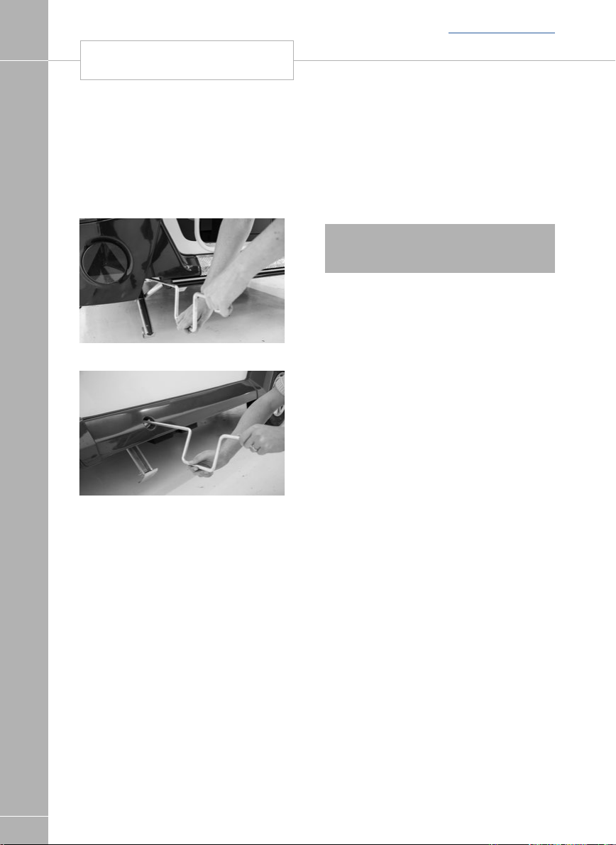
Fully raise all four corner steadies. (Fig. E & F).
Fig. E
Fig. F
Pick up any levelling pads or levelling boards.
Check windows/rooflights/vents are securely
closed.
Ensure television aerial is lowered (where
applicable).
Switch off gas supply and change fridge to
12V operation.
Lock the caravan exterior door.
Check all car and caravan roadlights are
working.
Check round the caravan for anything left
behind.
Fit extending mirrors
Release caravan handbrake, adjust all mirrors
from driving seat and proceed.
• All road lights must be in working order.
• Lenses and reflectors must be in good
condition
• Bulbs must be of correct wattage for the
application (see Service handbook).
! WARNING: Do not cause any road
lighting to be obstructed by the addition of
any options or accessories to your caravan.
20

13 Pin socket
Please be aware that some car manufacturers
and towbar manufacturers do not wire up all
13 pins as standard, unless requested.
Back to section menu
13 PIN SOCKET
TOWING CODE
21

TOW CAR ELECTRICS
Back to section menu
Tow Car Electrics
In all cases, The Swift Group assumes that the
tow car harness and electrics have been fitted
with the specific requirement of connection to
a caravan, which may contain AL-KO trailer
control (ATC), a 12V powered fridge and
TOWING CODE
charging circuits.
Most modern retro-fit towbars contain a relay,
located somewhere within the boot of the
tow car, which may have a selectable power
output for the fridge supply.
If a customer is experiencing issues with the
fridge supply it is possible the relay requires
adjustment and they should contact their tow
vehicle electrics installer or an auto electrician
to verify the installation.
LED Road Lighting
Your caravan maybe fitted with LED road
lighting, including the directional indicators and
stop lamps. LEDs consume very little power,
offer excellent light output and longevity when
compared to traditional tungsten bulbs.
Some more advanced tow cars are fitted
with Vehicle Light Monitoring Systems {VLM},
where the car monitors the condition of the
trailer/caravan road lights and advises the
driver of any bulb failures. To do this, some
tow cars expect to see a load on the caravan
lighting circuit similar to a tungsten bulb while
others may send a pulse of energy to each
light to confirm that the resistance of a bulb is
present.
The result of the above is that some tow cars
may incorrectly advise the driver of a bulb
failure, due to the use of LED lights while
others may flash or pulse the lights during use.
Recognising this, The Swift Group have
developed an additional towing fusebox,
which when connected to the existing towing
fusebox and is used to assist the towcar in
recognising the VLM System. Depending on
the type of car and system used the fusebox
maybe model specific.
The secondary fusebox is chargeable and
available through any Swift Group Dealer.
Note: This will change updates will be
required.
Caravan 13 Pin Connection - care advice
All caravans since 2008 have been supplied
with a 13 pin plug to connect to the towcar.
The 13 pin plug has an inner ring assembly
that is independent from the outer body.
Plug Inner Ring (containing
male pin terminals) - fitted to
Plug Outer Body with locating
groove and hood - fitted to
Socket Body (containing
female socket terminals) -
the caravan
the caravan
fitted to the car
Under normal circumstances the inner ring and
the outer body will be locked in one position
(see fig 1).
Fig 1
When the plug is first inserted in the socket
body ensure that the locating protrusion (key)
matches the groove (keyway) in the socket
body. The outer body can then be rotated a
full 90 degrees clockwise until a click is felt
or heard, at this point the cover flap can be
allowed to fall over the circular surface of the
plug top.
To remove the plug it is important to rotate the
outer body a full 90 degrees anti-clockwise,
again until a click is heard or felt before
withdrawing the plug from the socket. This will
ensure that the inner and outer parts of the
plug are returned to a locked condition.
22

Back to section menu
BREAKAWAY CABLE
TOWING CODE
WARNING: If the connector is not fully rotated
anti-clockwise prior to removing it from the
socket it is possible that the inner ring will
become ‘floating’ and may result in a condition
where the protrusion will be incorrectly aligned
(see fig 2 & 3).
Fig 2
Fig 3
If this situation does occur then it can be
corrected by inserting the edge of the
protrusion on the plug into the groove in the
socket (see Fig 4) and rotating the plug body
anti-clockwise until a click is felt. This process
will re-establish the lock between the inner and
outer parts allowing the correct insertion of the
plug into the socket.
Fig 4
Note: Customers should note that the
towbar and towcar electrical socket will
be checked as part of the standard MOT
regulations, under directive 2009/40/EC.
This not only applies to tow cars but also
all Motorhomes fitted with a tow bar and
socket. Inappropriate repair or modification
to either maybe deemed a failure of the
vehicle if it is likely to affect the road
worthiness of the vehicle.
Passengers
Passengers are forbidden to ride in a caravan.
Breakaway cables
UK law requires that all caravans are fitted
with a safety device to provide protection in
the unlikely event of separation of the main
coupling while in motion. A device referred to
as a ‘breakaway cable’ fulfils this requirement
and when fitted as on your caravan is
mandatory.
Purpose
To apply the caravans brakes if it becomes
separated from its towing vehicle. Having done
this, the cable assembly is designed to part
allowing the caravan to come to a halt away
from the towing vehicle.
Construction
A thin steel cable with a red plastic coating
fitted with a means of attachment for
connection to the towing vehicle. Located
directly beneath the coupling head.
Operation
In the event of the main coupling of the
caravan separating from the towing vehicle,
the cable should be able to pull tight, without
any hindrance, engaging the caravan brakes.
The breakaway cable should not become taut
during normal driving.
Correct procedure for use
Regularly check the cable and clip for damage.
If in doubt contact your Swift Group dealer.
Make sure the cable runs as straight as
possible and goes through the cable guide
fitted underneath the caravan coupling head.
23

BREAKAWAY CABLE
Determine whether or not the towing vehicle
towbar has a designated attachment point
(i.e. a part specifically designated for a
breakaway cable).
Where a point is designated on the towbar:
• Either pass the cable through the attachment
TOWING CODE
point and clip it back on itself (Fig 1)
or attach it directly to the designated point
(Fig 2).
Fig. 1
Fig. 2
Where there is no designated attachment point
on the towbar:
• Fixed ball: Loop the cable around the neck
of the towball in a single loop only. See figure
3A and 3B.
Back to section menu
Fig. 3a
Fig. 3b
In some instances it may be possible
to attach the cable assembly either to a
permanent part of the towbar structure, as
long as this meets the approval of the towbar
manufacturer/supplier, or to an accessory sold
for the specific purpose of breakaway cable
attachment. For vehicles fitted with detachable
towbars, guidance must be sought from the
towbar manufacture/supplier on the correct
method for attaching the breakaway cable.
When the breakaway cable is attached it must
not snag in use on the trailer coupling head,
jockey heel or any accessories, e.g. a stabliser,
bumper shield, cycle carrier, etc. There should
also be sufficient slack in the cable to allow
the towing vehicle and trailer to articulate fully
without applying tension to the cable which
could otherwise cause the trailer brakes to be
inadvertently applied.
The cable must not be allowed to drag on the
ground. If there is too much slack, the cable
might drag on the ground and be weakened
so that it has insufficient strength to apply the
brakes in the event of the trailer becoming
detached when in motion. Excess slack may
also lead to the cable being caught on an
obstacle when in motion, leading to inadvertent application of the trailer brakes. Care must
be also taken to ensure that the cable cannot
be entangled with the electrical cables.
24
Back to section menu
MOVING OFF
TOWING CODE
Mirrors
The driver of the towing vehicle must have an
adequate view of the rear.
If there is no rear view through the caravan it is
essential that additional exterior towing mirrors
are fitted. This is mandatory in some European
countries and drivers can face instant fines if
extension mirrors are not fitted.
! WARNING: Any rear view mirror must
not project more than 250 mm outside:
a. the width of the caravan when being
towed.
b. the width of the towing vehicle when
driven solo.
Note: Any rear view mirror fitted shall be
‘e’ marked and cover the field of view as
stipulated by type approval requirements
(Community Directive 2003/97 or 2005/27
or ECE Regulation 46.02 or Regulation 33
of the Road Vehicles (Construction & Use
Regulation 1986).
Moving off
Let the clutch in smoothly.
Allow more engine speed to produce the
power to move the additional weight of the
caravan.
Reduce wear and tear on clutch and
transmission by taking extra care.
Change gears smoothly.
Try not to jerk the clutch.
Reversing
When the towing vehicle is reversing, the
overrun device shaft is pushing in, applying the
brakes via the overrun lever, brake rod system,
bowden cables and the expander mechanism.
Fig. A Reversing
The backwards rotation of the brake drum
causes the secondary brake shoe to collapse
cancelling out the braking effect, allowing the
caravan to move backwards. At the same
time the transmission lever swings back and
compensates for the entire travel.
When reversing up a slope or on a loose
surface the brakes may apply themselves,
Correct maintenance and set up of the brakes
will help prevent this. Incorrect adjustment
of the wheel brakes or linkages will result in
making reversing difficult.
Proficiency at reversing can only be achieved
with practice and should be first attempted in
a large open area (Fig. A).
Speed limits
Single carriageways: 50mph
Motorways (including dual carriageways):
60mph
25

CARAVAN HANDLING
Back to section menu
Caravan handling
Allow for caravan being wider than car.
Do not bump kerb with caravan wheels.
When passing other vehicles allow more than
the normal clearance for driving solo.
TOWING CODE
Allow longer to build up speed to pass.
Allow for the outfit being twice its
normal length.
Do not suddenly swing out.
Carry out all manoeuvres as smoothly
as possible.
Use nearside wing mirror to check caravan has
cleared when overtaking.
! WARNING: Take care not to foul or
ground caravan chassis whilst traversing
ramps or other obstacles.
Motorway driving
Important points
1. Caravans may not be towed in the out- side
lane of a three or four lane motorway. (Reg.
12(2) of the Motorway Traffic [England and
Wales] Regulations 1982).
2. Reduce Speed:
a. In high or cross winds
b. Downhill
c. In poor visibility
3. High sided vehicles cause air buffeting so
extra care must be taken when passing or
being passed. As much space as possible
should be given.
Spare wheel
The spare wheel is located in the gas locker at
the front of the caravan.
Note: The side-lift jack (when fitted) has a
maximum lifting height of 375mm and the
scissor jack a maximum lifting height of
340mm.
26

Back to section menu
CHANGING A WHEEL
TOWING CODE
Changing a wheel
1. Leave caravan hitched to towing vehicle and
ensure that the caravan and towing vehicle
handbrakes are applied.
2. Lower corner steadies (as safety measure)
on the side that is being jacked up.
3. Remove wheel trims (if fitted).
4. Use wheel brace to slacken off wheel nuts
on the wheel to be changed.
5. Position jack under the axle at the
appropriate jacking point
(see Fig. B, page 34)
6. Jack up the caravan until the wheel for
removal is just off the ground.
7. Remove the wheel nuts and remove
the wheel.
8. Fit spare wheel and reverse the above
procedure. Ensure clean, dry mating
surfaces and clean, dry bolt/nut sealing
areas.
9. Ensure the spare wheel is free from damage
and distortion
10. Tighten all five bolts, according to
Fig. A, to 88Nm (65lb/ft) for steel wheels
or 130Nm (96lb/ft) for alloy wheels using a
torque wrench or have checked as soon as
possible. Ensure the correct wheel fixings
are used, as supplied with your caravan.
! WARNING: When a wheel has been
removed and replaced the torque of the
wheel nuts should be re-checked after
approximately 50 miles.
Wheel bolt tightening
When refitting a wheel it is ESSENTIAL that the
wheel bolts are tightened to the recommended
torque figure and in the correct sequence.
The sequences necessary to correctly carry
out this work on a 5 stud wheel is as follows:
1
3
5 Stud
5
Fig. A
Please note the correct torque settings.
4
2
Jacking points
! WARNING: Only jack up your caravan
when it is coupled up to the car with its
handbrake applied and in 1st gear
(engine off).
Ensure that the jack is located in the correct
position, i.e. on the jacking bracket on the
chassis for the AL-KO side mounted jack
(Fig.B). Alternatively the reinforced axle
mounting plate can be used but the chassis
member itself MUST NEVER be used as a
jacking point.
All caravans are provided with the facility to
fit AL-KO side jacking points and although a
scissor, trolley or bottle jack may be used.
Ensure the lifting capacity of your jack is
suitable for your caravan.
Note: Only use a suitable wheel brace to
loosen and tighten the wheel bolts. Do
not use the corner steady brace for this
application.
27

STOPPING ON A HILL
TOWING CODE
Fig. B Side lift jack
Stopping on a hill
Pulling off again can sometimes present a
problem. The easy solution is
1. Carry a good sized wedge shaped piece of
wood with a rope or light
chain attached.
2. Attach the other end of the rope to the
nearside rear grab handle.
3. Place the wood behind the nearside
caravan wheel.
4. Carefully reverse the car slightly back down
the hill, the caravan will stop against the
wedge and turn.
5. Drive forward since this attempt to move
up the hill will now not involve pulling the
full weight of the caravan until the car has
gained some traction.
6. When reaching the top of the hill retrieve
the wedge.
Arrival on site
Note: Check and observe site regulations.
Manoeuvring your caravan by hand
Back to section menu
1. Selecting a pitch
Do not pitch in such a position that your outfit
will obstruct others coming in.
Try to choose an area which is dry, reasonably level and preferably with a hard base.
If you have no alternative but to pitch on a
slope ensure that, for when you leave, you are
facing down the slope.
Ensure sufficient space is left at the rear of the
caravan (4m) for the awning
It is good practice to chock the wheels of the
caravan when parked on a slope even though
the caravan brakes are applied.
2. Levelling the caravan
Levelling must be carried out in both directions
in order for the refrigerator and other
equipment to function correctly. This should be
done before unhitching the caravan. Levelling
boards (Fig. C) can be used to raise one side
of the caravan by driving or reversing the
caravan onto the boards. Apply the handbrake
and chock the wheels.
The positioning of the jockey wheel can be
used to help level the caravan.
Lower the corner steadies until they are in firm
contact with the ground.
! WARNING: DO NOT use the steadies
as a jack they are only a means of stabilising
the caravan.
Levelling pads or boards should be used
under the steadies where the ground is soft or
uneven.
In extreme cases where it is necessary to raise
a wheel off the ground for levelling purposes,
further adequate support should be applied so
that the steadies do not take any undue strain.
28
Note: Care must be taken when
manoeuvring your caravan into position.
Pressure placed on unsupported parts
of front and rear GRP panels may cause
surface damage/ cracks to appear. Use the
grab handles provided.

Fig. C Levelling board
Exterior door
To prevent distortion of the body, the caravan
must be always correctly sited and levelled.
Failure to site the caravan correctly may
prevent the exterior door from closing properly.
3. Unhitching
Before applying the handbrake ensure the
hitch is fully extended and not compressed
behind the tow vehicle otherwise the hitch will
not release from the tow ball.
Apply the caravan handbrake.
Lower the jockey wheel to the ground.
Disconnect the breakaway cable and road
lighting plugs.
AK160
Lift the coupling handle to release the locking
tongue (fig A page 24), whilst simultaneously
winding down the jockey wheel, to lift the
caravan hitch head clear of the tow ball.
Back to section menu
UNHITCHING
TOWING CODE
29

Back to main menu
SAFETY AND SECURITY
Fire .......................................................................................................................................... 32
SI 601 Smoke Alarm Operation ............................................................................................... 32
Fire extinguisher ....................................................................................................................... 32
Escape paths .......................................................................................................................... 32
Children ................................................................................................................................... 32
CO Alarm - Fireangel CO-9X Carbo Monoxide Alarm operation ................................................ 32
Ventilation ................................................................................................................................ 33
Security ................................................................................................................................... 33
Swift Command tracker ............................................................................................................ 34
AL-KO Secure immobiliser ........................................................................................................ 35
Mobile Alarm System ............................................................................................................... 36
SAFETY AND SECURITY
31

FIRE / SMOKE ALARM / CO ALARM
Back to section menu
Fire
Important: Your attention is drawn to the
notice affixed inside the caravan wardrobe
advising on fire precaution, ventilation and
what to do in case of fire.
In case of fire
1. Get everyone out of the caravan as quickly
as possible using whichever exit is the
quickest, including windows. Do not stop to
SAFETY AND SECURITY
collect any personal items.
2. Raise the Alarm. Call the Fire Brigade.
3. Turn off the gas supply valve if it is safe to
do so.
4. Turn off the electricity supply at
supply point.
Smoke Alarm operation
Your caravan is fitted with a Fire Angel S0-601
smoke alarm. Please read the user instructions
for the smoke alarm, which are available at the
following location:
http://fireangel.co.uk/wp-content/
uploads/2015/07/SO-601%20Manual.pdf
If you are unable to view the documents on
line, please contact the supplier, your dealer or
Swift for an electronic or paper copy.
Fire Extinguisher
It is recommended that a dry powder fire
extinguisher be carried inside your caravan at
all times.
When using a dry powder extinguisher it is
suggested that the caravan be evacuated until
the powder has settled, to avoid inhalation.
A fat pan fire should not have a fire
extinguisher aimed at it. It should be
smothered with a fire blanket.
! WARNING: Provide one dry powder
fire extinguisher of an approved type or
complying with EN 3-7 or ISO7165, of at
least 1kg capacity, by the main exterior door
and a fire blanket next to the cooker.
Familiarise yourself with the instructions
on your fire extinguisher and the local fire
precaution arrangements.
Escape paths
It is important that you do not block escape
paths to emergency exits with obstructions
or hazards.
Children
Do not leave children alone in the caravan
in any event. Keep potentially dangerous
items out of reach, as at home e.g. matches,
medicine etc.
CO alarm
Fireangel CO-9D Carbon Monoxide Alarm
Your caravan is fitted with a Fireangel CO-9D
Carbon Monoxide Alarm . Please read the
instructions for the alarm, which are available
at the following location:
http://fireangel.co.uk/wp-content/
uploads/2015/07/CO-9D%20Manual.pdf
32
If you are unable to view the documents on
line, please contact the supplier, your dealer or
Swift for an electronic or paper copy.

Back to section menu
VENTILATION / SECURITY
SAFETY AND SECURITY
Ventilation
All caravans comply with BS EN 721.
The ventilation points on your caravan are fixed
points of ventilation which are required by the
European Standards.
All caravans have ventilation at high level and
low level which have been calculated to suit
the individual needs of your caravan.
High level ventilation is achieved by means of
the roof lights and washroom roof ventilators.
The low level ventilators are positioned
underneath the oven housing.
Under no circumstances must these vents be
blocked or obstructed in any manner as this
could lead to insufficient fresh air. In this case
the confined atmosphere becomes depleted of
oxygen which could lead to dangerous levels
of carbon dioxide (CO2) build up leading to risk
of asphyxiation.
The risks of carbon monoxide (CO) build
up, which is a colourless, odourless and
tasteless gas, will also be reduced with
ventilation. Carbon monoxide is produced
from incomplete combustion and should the
CO detector be activated the cause of the
incomplete combustion must be investigated
prior to reusing the appliance in question.
It is advised that fixed ventilation points
are checked and cleaned (if necessary) on
a regular basis using a small brush and a
domestic vacuum cleaner.
Additional night time ventilation is obtained
by releasing the window catches and placing
them in the second groove. Note the windows
are not sealed from rain in this position.
As the ventilation levels are calculated to suit
each models requirements there should be
no modifications made which may result in
reduced ventilation levels.
! WARNING: Do not obstruct ventilation
Petrol/Diesel Fumes
The fitting of a tail pipe extension to your
car exhaust will reduce the possibility of
fumes entering your caravan through the
ventilation points.
Security
Caravan theft
The theft of a caravan can occur in the most
unlikely circumstances; from a motorway
service area, even from an owner’s driveway.
Secure all windows and doors when your
caravan is unoccupied even if only for a short
length of time.
Security chips
A special security chip is concealed within
the body of every caravan. This chip contains
the individual identity of your caravan and can
only be read using a special decoder by police
officers.
Chassis number
Your 17 digit serial number chassis number
can be found on your windows and on the
offside chassis member of the drawbar. It is
also stated on the manufacturers weight plate
next to the doorway.
Make a note of this number in the space
provided at the front of this handbook and
make a separate note of the number to keep
safe at home.
Additional security
Consider fitting any device which might deter
or prevent intrusion by thieves.
A hitch lock cover prevents towing of
the caravan.
A wheel lock prevents towing of the caravan
and removal of the wheel.
Customers are advised to identify their caravan
with a method for subsequent identification if
other forms of identification have been altered
or removed.
Free crime prevention advice about securing
your caravan, protecting your valuables,
property marking, either at home or whilst
on site, can be obtained from the Crime
Prevention Officer through your local
Police Station.
33

SWIFT COMMAND TRACKER
Back to section menu
Caravan insurance
It is recommended that the caravan and its
contents should be insured against theft.
It is essential to check with your car insurance
company to ensure you are covered when
towing your caravan.
Swift Command Tracker
by Sargent
A Swift Command Tracker is built in to your
SAFETY AND SECURITY
vehicle and forms part of the Swift Command
system.
The unit is Thatcham Category 6 certified and
is monitored by an approved monitoring centre
which operates 24 hours a day 7 days a week
and provides European coverage and direct
police liaison.
This system is ready for use, all you need to
do is purchase a tracking subscription by
visiting www.swiftcommand.co.uk or calling
Sargent on 01482 881655.
The subscription cost is £95 per year
including VAT.
For more information please visit
www.swiftcommand.co.uk
Operation
The Swift Command Tracker is easy to
operate as it is controlled by the vehicle
systems.
In a caravan the tracker is armed when the
Stinger 310 / 350 Alarm System is armed. It is
disarmed when the alarm is disarmed.
If the caravan doesn’t have an alarm system
fitted, a simple numeric keypad is used to arm
/ disarm the tracker. Enter your code followed
by the ON button to arm the tracker.
Enter your code followed by the OFF button to
disarm the tracker.
Event of a Theft
If the vehicle is moved whilst the tracker is
armed the geo-fence monitoring will trigger a
theft event.
In addition to the above, in a caravan with the
Stinger 310 / 350 Alarm System fitted, if the
alarm is triggered by internal movement or
caravan tilting the alarm monitoring will also
trigger a theft event.
The monitoring station will now contact you
to confirm the theft or false alarm. You will
be required to confirm your identity against
the information you provided when you
subscribed.
If a genuine theft is confirmed the monitoring
station will liaise with the police and keep you
informed of progress.
Note; during a theft event to comply with
legislation you will not be able to manually
locate your vehicle using the Swift Command
locate feature.
Contact
Before contacting any of the following please
ensure you know your caravan serial number.
For caravans this is the last 10 digits if the
CRIS number (like SWG0123456).
The Swift Command Tracker monitoring
station can be contacted on 0345 6027302.
The stations operates 24 yours a day 7 days
a week.
Sargent customer support can be contacted
on 01482 678981 or via support@
swiftcommand.co.uk
Telephone lines are manned during normal
office hours.
Swift customer support can be contacted on
01482 875740 during normal office hours.
34
cont...

Back to section menu
AL-KO SECURE IMMOBILISER
SAFETY AND SECURITY
Precautions
The Swift Command Tracker monitors the
leisure battery supply and if the voltage falls
below a set level or the battery is removed this
will trigger a fault event.
If you plan to remove your battery for
maintenance or external charging please
contact the monitoring station BEFORE
removing the battery
If you lose an alarm key fob you need to
contact Sargent for a replacement and follow
their instructions to remove the ‘lost’ fob from
the system.
If you lose an ignition key you will need to visit
a Fiat dealer for key replacement and removal
of the ‘lost’ key.
.
AL-KO Secure immobiliser
(when fitted)
The AL-KO immobiliser is optional on
Basecamp and is not compatible with steel
wheels. The Basecamp requires the 'Secure
Plus' kit as the secure receiver needs fitting to
the nearside brake drum assembly. Your dealer
will need to fit the receiver in their workshop
by stripping down the brake and reassembling
with the additional secure parts, this will
include the replacement of the brake drum one
shot nut.
The secure wheel lock is specific to the 'Edge'
alloy wheel fitted. The Secure Plus kit is Swift
Part number 9840476 and ALKO number
1559516. Once the secure receiver is fitted to
the nearside brake assembly, you will have a
part kit as specified below.
Part A
Box containing security components.
consisting of:
- 1off High security locking bolt.
- 1off High security locking bar socket key.
- 1off Barrel lock.
- 2off Barrel lock keys.
- Instruction manuals in CD and paper format.
- Security registration card and reference
number.
Part B
Wheel specific insert assembly consisting of:
- Red coloured wheel insert lozenge
assembled with the locking bar and clip.
Part C
- 1off Wheel spanner.
Part D
- Kit bag.
You must register your key within one
month of the date of purchase. Should
you fail to do this, you will not be able to
order a spare key!
- Within your AL-KO kit you will find an
exclusive security number.
- Please register your card by telephoning
0870 7576788 or 0044 1926 818500.
Safety information
(AL-KO Secure)
- Always secure the caravan against rolling
away (chock or couple to a towing vehicle).
- Always remove AL-KO Secure before moving
the caravan.
- After any attempt of theft has been made on
a locked AL-KO Secure, the caravan must
be inspected at an AL-KO Approved Service
Workshop.
- Always keep the key in a safe place.
- Keep the lock set and registration card
separate from the key.
- The lock parts and key do not have a
registration number, therefore keep the
registration card in a safe place.
- Caravans with twin axles have two locks,
keep each lock set in a separate place.
The sets are not interchangeable!
35

AL-KO JACK / MOBILE ALARM SYSTEM
AL-KO operating instructions
- Read the AL-KO operating instructions and
act in accordance with them.
- Follow all safety instructions as well as the
warning information.
- It is recommended for ease of fit that a sidelift jack be used.
- Keep the operating instructions
The AL-KO side lift jack
SAFETY AND SECURITY
(Supplied as standard on specific models only).
The AL-KO Side Lift Jack has been
specifically developed to aid the often difficult
process of changing a wheel on caravans.
It is suitable for fitment to the AL-KO
chassis, located in the pre-drilled holes in the
longitudinal members.
Note: The fitment of some aftermarket
motor movers may inhibit the use of the
AL-KO jacking system.
Back to section menu
36
Mobile alarm system
Depending on specification, your caravan may
be fitted with a Sargent AS310 Stinger Alarm
System. Please read the instructions for the
alarm, which are available at:
https://sargentltd.co.uk/tech-support/
article/Alarm-Manuals/21
If you are unable to view the documents on
line, please contact the supplier, your dealer or
Swift for an electronic or paper copy.

Back to main menu
SERVICES
Water System ........................................................................................................................ 38
Plumbing connections ........................................................................................................... 40
Plumbing troubleshooting ...................................................................................................... .41
Pressure switch adjustment .................................................................................................... 42
Sanitising water system ......................................................................................................... 42
Water Fault Finding ................................................................................................................ 44
Typical gas schematic drawing .............................................................................................. 46
Gas ...................................................................................................................................... 47
Types of gas ......................................................................................................................... 48
Gas safety advice ................................................................................................................. 48
Awning space ventilation ...................................................................................................... 49
Changing a gas cylinder ........................................................................................................ 49
Gas Fault Finding .................................................................................................................. 51
Electrical system ................................................................................................................... 52
Overseas connection ............................................................................................................ 52
13 Pin tow vehicle connections ............................................................................................. 53
230V mains electrical equipment power consumption .......................................................... 54
Wiring of connecting cable and caravan mains inlet .............................................................. 55
Typical appliance consumption figures .................................................................................. 56
SERVICES
37

WATER SYSTEM
Water system- Introduction
All Swift Group caravans water systems have
been designed around a pump fitted within
SERVICES
the caravan. This pump draws water from an
external source, to provide water pressure
within the caravan, whenever it is switched on
and water is available.
The schematic below shows the basic
configuration of the water system with inboard
pump and no internal water tank:
Back to section menu
38
When power is supplied to the pump, it will
draw water from the external container through
the water inlet mounted on the side of the
caravan, and pump it to the caravan taps,
shower and water heater.
The pump is fitted with its own pressure
switch, and the pump will continue to pump
water, until the pressure of water on the output
of the pump reaches a pre-set level. For this
pressure to be achieved, the taps must be
closed.
When the taps are opened, water will leave
the tap via the spout, and the pressure in the
pipes between the pump and the taps will
reduce. Because of this reduction in pressure,
the pressure switch on the pump will switch
back on and the pump will again run to pump
more water.
Close to the pump, the water under pressure
is split into two paths:
1. Through blue water pipes routed directly to
the cold connection of each tap.
2. To the water heater.
Water from the pump enters the bottom of the
water heater. Once the water fills the water
heater (approx 8.5 litres), water then leaves the
water heater via a connection at the top of that
water heater. This water, which is still under
pressure, then routes to the hot connection of
each tap via red pipes.
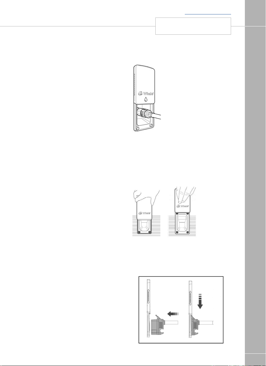
Back to section menu
WATER SYSTEM
SERVICES
On Arrival at the campsite /
Priming the system
• Ensure that the external water container
is full. An umbilical hose with baffle is
supplied with your caravan to connect
between the inlet and aqua roll or similar
container.
• Close all of the taps (kitchen sink, bathroom,
shower) except one, which should be open
in the hot position.
• Ensure that the water heater drain valve is
closed (move the Yellow handle on the floor
near the water heater to a
horizontal position).
• Switch the pump on using the button on the
control panel. Water will flow through the
open tap after a short time. This tap can then
be moved to the cold position and again
after a short time water will flow.
• Repeat the procedure at each tap, including
the external shower point
(model specific)
• When using a mains water connection
the pump will still need to be switched on to
supply water to the water heater,
taps and shower.
• If a mains water connection is used, please
ensure this is a Whale Watermaster mains
water hook-up, which has a built in pressure
reducing valve.
• To drain / winterise the system please see
separate details later in this handbook.
Whale Water In Socket and Watermaster®
exterior water pump with Easi-Push Plug
(when fitted)
To use the water inlet:
1) Fill an external water container, and position
the container near the Whale water inlet on
the side of the caravan.
2) Slide the lid upwards, by gripping the sides
of the lid, as shown on the image below:
Opening sliding lid
3) Place the hose and filter supplied with the
caravan, into a full water container
4) Insert plug into water inlet and slide lid down
to lock plug in place as shown in the image
below:
39

PLUMBING CONNECTIONS
Back to section menu
5) Adjust dust cover over opening in water
container as shown in image below. Please
note dust cover should not be secured to
SERVICES
water container, as air must be allowed to
enter the container to replace the water being pumped out..
Plug connector to inlet, with
hose in water container, and
dust cover in place
Slide lid up to unlock and remove plug. When
removing the plug, simply pull the plug clear of
the socket using the hand grip.
Please note: It is recommended that you
change your Whale water filter every 3000
litres or after approximately 30 days of use as
smells and debris will build up in the filter and
effect the pump’s performance. No other maintenance is required.
WARNING: This filter cartridge should not
be used in water supplies of an unknown
bacteriological quality. This is not a bacterial
filter.
Plumbing Connections
In most cases, speed fittings are used,
which allow easy and quick connection of
water pipes.
To connect a pipe to a fitting, simply push the
pipe into the connector. To remove the pipe,
push the collar of the fitting inwards, and then
withdraw the pipe.
To connect a pipe, simply push the pipe into
the connector.
To remove a pipe, push the collar inwards, and
then remove the pipe.
As a note, when refitting the pipe, ensure
the end of the pipe is round (not oval) and
the cut is square. If not, it could lead to
water leaks.
40

Back to section menu
WATER SYSTEM TROUBLESHOOTING
SERVICES
Troubleshooting
Pump will not start, when the tap is
opened:
• Check fuse(s).
• Check power source(s), and ensure there is
sufficient voltage to run the pump.
• Ensure 'pump' LED is illuminated.
• Using a multi-meter, ensure there is power at
the pump. If not, refer to your dealer as there
maybe damaged cabling or a fault with the
fusebox.
• Is the pump hot? If so, allow to cool
before retrying.
• Has the vehicle been stored over winter?
Was it correctly winterised? If no, the pump
may have frozen, causing permanent
damage.
• The pressure switch may need adjusting.
See page 60 on how to do this.
Pump runs, but will not pressurise system
(i.e. no or little water being discharged
from taps) - Not Pulsing:
• Ensure water in source is present (onboard
tank or aqua roll).
• Check in-line pump filter is free from debris
and correctly fitted.
• Ensure water system has been primed
correctly, (see page 57) and there are no
air-locks present.
• Ensure there are no restrictions
in the plumbing.
• Using a multi-meter, ensure there is power at
the pump. If not, refer to your dealer as there
maybe damaged cabling or a fault with the
fusebox.
• Ensure the inlet side of the pump (including
Truma inlet and in-line filter)
are watertight and not allowing air into
the system.
• Ensure the pump has good voltage.
• Check (using a multi-meter) that the voltage
at the pump is between 10v-14.5v.
Pump continues to run (for more than 5
seconds) after taps are closed or pump
turns on for no reason:
• Check for leaks on the high pressure side of
the pump.
• Ensure water system has been primed
correctly, (see page 57) and there are no
air-locks present.
• Ensure the pump is securely mounted.
• Ensure the piping on the high pressure side
of the pump is in good condition (not blowing
or deforming).
• The pressure switch may need adjusting.
See page 60 for information on how to do
this.
Noisy or rough operation
• Check for leaks on the high pressure and
low pressure side of the pump.
• Ensure that all pipes (especially those within
150mm of the pump) are not touching any
furniture.
• Ensure the pump is securely mounted.
Pump rapidly cycles (switches on or off)
or water pulses from taps, including temperature pulsing:
• Check for leaks on the high pressure and
low pressure side of the pump.
• Ensure there are no restrictions in the
plumbing
• The pressure switch may need adjusting.
See page 60 for information on how to do
this.
41
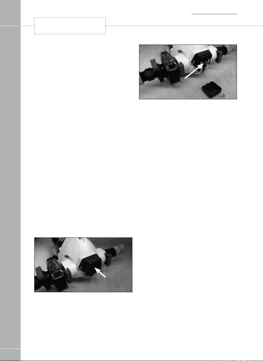
Water pump pressure switch
The purpose of a pressure switch is to monitor
the pressure on the outlet side of the pump.
SERVICES
When a tap is closed, and the pump continues
to run, there is an increase of pressure in the
system, and when that pressure reaches a
pre-set limit, the pressure switch will turn the
pump off.
Water pump pressure
switch adjustment
Pressure Switch Adjustment, Truma/Flo-Jet
pump. (Normally Grey upper section with
White lower section/valve housing)
• All of the Truma/Flo-Jet pumps used by Swift
• To further adjust the pressure switch setting,
• Please note a second screw mounted
42
WATER SYSTEM
are pre-set at 25psi - 31psi.
a cover cap must be first be removed from
the end of the pump to reveal a pressure
adjusting screw, as shown in the photos.
A maximum of 1/4 turn clockwise or
anti-clockwise, from the factory setting, is
advised. Turning the screw clockwise 1/4
turn will increase the pressure switch cut-out
pressure, turning the screw anti-clockwise
will reduce the pressure setting.
below the cover cap is set in position with
threadlock, this should not be disturbed.
Cover cap
Back to section menu
Pressure switch
adjusting screw
Sanitising
Guidance on cleaning portable water
tanks and the water system in touring
caravans.
The water systems, and in particular water
tanks, in caravans are susceptible to
contamination by bacteria if care is not taken
with their use and cleaning. The symptoms
caused by bacterial contamination are not
purely limited to gastro-intestinal diseases,
but may also manifest themselves as ear,
nose, throat, eye or skin infections. It is
therefore important that you carry out the
following procedure prior to using the caravan
each time, even if you boil or filter all water you
use for drinking.
Separate Water Containers
1. All water remaining in the container
should be disposed of so that the container
is empty.
2. The outside of the container should be
thoroughly cleansed and washed down to
remove any dirt, dust or other contaminant.
Water at a suitably hot temperature
containing an appropriate detergent is
recommended for this purpose.
3. Water should be put in the container, swirled
around, then emptied out.
4. The container should then be totally filled
with water containing an appropriate
sterilant solution and allowed to stand for
the recommended contact time.
5. The solution should be emptied from
the container.
6. The opening of the container should be
cleaned thoroughly with an appropriate
prepared wipe impregnated with a sterilant.

7. The container should be inverted whilst
stored overnight (if possible).
8. The container must be filled with mains
water only and mains water only should be
used for the above cleaning procedure.
9. On no account should garden hoses be
used to fill water tanks.
For Systems:
1. Drain down the system (open all taps
to allow air in, enabling the system to
drain quickly).
2. Remove any after market water filters fitted,
and replace with a short length of hose or
empty filter cartridge (this will ensure the
filter is not affected by the disinfectant/
sterilant solution).
3. Fill the system by using the pump with a
disinfectant/sterilant solution (check that
the solution at full strength appears at
all taps/showers). Allow to stand for the
recommended period of time.
4. Drain the system completely.
5. Thoroughly clean the outside of all taps/
connectors with a cloth soaked in the
disinfectant/sterilant.
6. Flush the system through with clean drinking
water until no traces of disinfectant/sterilant
can be detected at any tap.
7. Replace the filter.
Suitable sterilising chemicals are available from
your caravan dealer, accessory shop, chemist
or home-brew shops. It is not, however,
recommended to use bleach or sodium
metabisulphite.
Do not use products that contain aggressive
agents for sterilising the water system.
Back to section menu
SANITISING WATER SYSTEM
SERVICES
NOTE: Never use the water heating system
when disinfectant/sterilising fluid is present.
Doing so may damage the system.
43

WATER FAULTS
Water
Fault Cause Remedy
SERVICES
Water not
flowing from
any tap when
operated but
pump runs
Pump does
not run
Water flows
from cold tap
but not from
hot
Freshwater tank empty
Pump wired in reverse
Pipe inlet or outlet pipe
disconnected
Pump pipes restricted
by kinking
Blockage in pump inlet or
outlet pipe
Blocked in-line filter of
pump filter
Air leak in suction line
to pump
Pump or tap
incorrectly wired
Pump fuse blown
Battery disconnected
Pump seized or overheated
Pressure pump sensing
switch may have failed
Contacts may be faulty
Wiring connections may
be faulty
Feed pipe to water heater
incorrectly connected to the
heater outlet
Blockage in hot pipeline
Heater inlet or outlet pipes
kinked preventing flow
Hot tap not connected
Hot tap failed or blocked
Heater non-return valve
jammed
Back to section menu
Check
Check wiring, refer to pump manufacturers
instructions
Check connections
Check pipes run
Check, starting inside freshwater tank
Dismantle and clean
Check for bubbles.
Refer to pump/tap manufacturers instructions
Check wiring connection and then replace with
fuse of correct rating
Check connections
Refer to pump manufacturers servicing
instructions
Refer to pump manufacturers servicing
instructions
Check contacts in plug and socket are clean
and making contact
Check wiring connections
Refer to installation instructions
Disconnect pipes and inspect.
Check and re-route if necessary.
Check pipe and connect where required.
Disconnect and inspect.
Refer to dealer.
44

Water
Fault Cause Remedy
Water flows
from hot
tap but has
reduced flow
from cold
Cold water pipe kinked
preventing flow
Blockage in cold pipe line
Cold tap not connected
Cold tap failed or blocked
Check and re-route if necessary
Disconnect pipes after 1st connector and
check up to tap
Refer to installation instructions
Disconnect and inspect
Back to section menu
WATER FAULTS
SERVICES
Reduced flow
from both hot
and cold taps
Reduced flow
from either tap
If pump motor
runs steadily
and will not
stop
Battery condition low
causing pump to
run slowly
If new taps have been fitted
they may be restricting flow
Pump needs servicing
Partially blocked pump filter
or in-line filter, if fitted
Pump outlet pipe kinked
restricting flow
Water leak
Pipe kinking restricting flow Check and re-route if necessary
Battery voltage may be
too low (below 10.5 volts)
Pressure Switch setting
problem
Check battery state of charge,
refer to electrical supply note
Disconnect and check that they have at least
1/4” (6.3mm) bore
Refer to pump servicing instructions
Dismantle and clean if necessary
Check and re-route if necessary
Check all water connections
Check that there is water in the container
Adjust switch and/or re-charge battery
Check all connections in pipework.
Adjust settings.
45
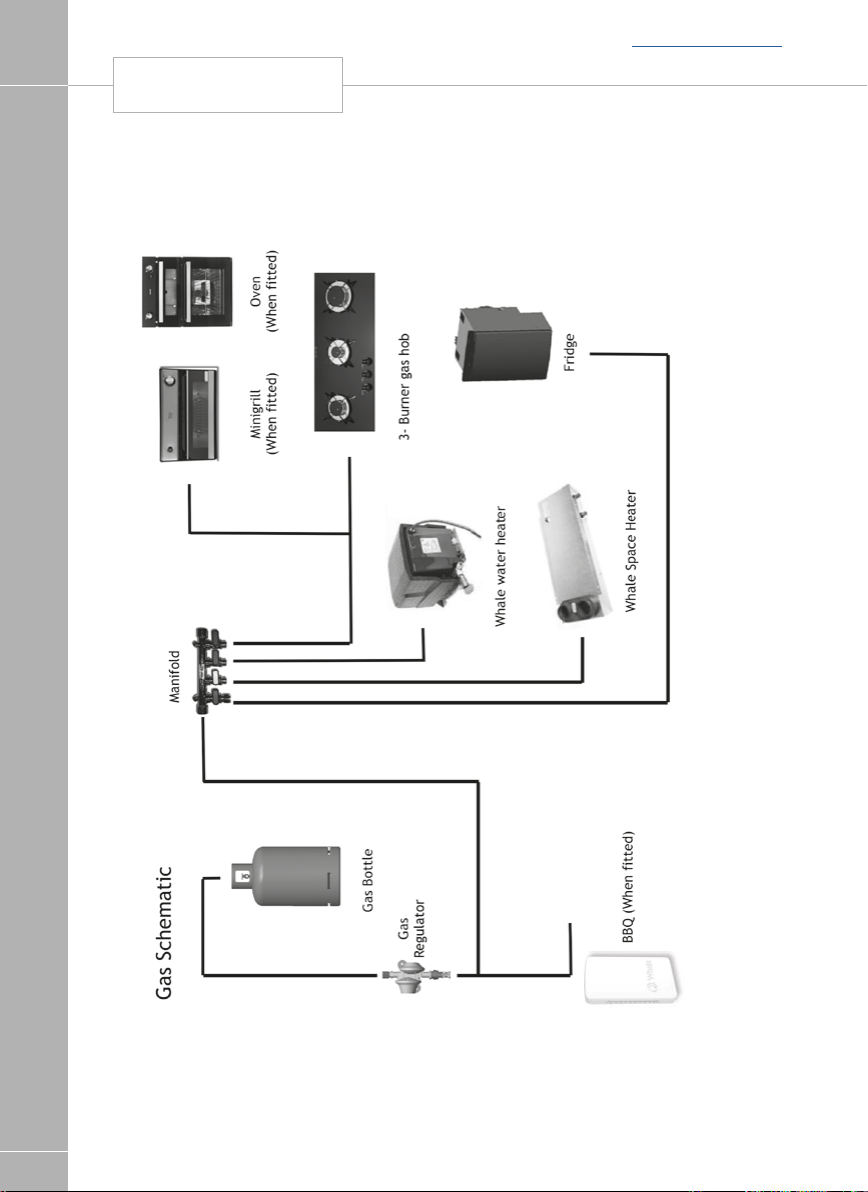
GAS SCHEMATIC
SERVICES
Back to section menu
46
Gas schematic

Back to section menu
GAS
SERVICES
Gas
General information
Gas Cylinders
Bottled Liquified Petroleum Gas (LPG) is the
most convenient portable source of fuel for
your caravan. Make sure that heating and
cooking appliances and the gas cylinders are
switched off before you move the caravan.
Regularly check flexible gas hose, joints and
connections for tightness.
Finally make sure that each gas appliance is
working efficiently to the recommendations of
the appliance manufacturers.
Only use gas bottle cylinders that are located
within their dedicated position within the front
gas bottle housing, never extend hose - hose
lengths must not exceed 400mm.
Gas Hoses
A high pressure hose must be used with the
regulator to connect to the gas bottle.
LPG cylinders i.e. Propane, Butane and
Camping Gaz cylinders all have varying
cylinder adaptor connections. It is important to
check you have the correct hose and adaptor
to suit your gas cylinders. Push on hoses are
no longer permitted under the new regulations,
The new high-pressure hoses have threaded
connections and must be securely attached to
the regulator and to the gas cylinder.
The pressure regulator relies upon a sealing
washer(s) to maintain a gas tight joint, and
it is essential to check that the washer is
present, sound and correctly positioned prior
to making the connection. The gas cylinder
connection relies on a metal seating or bull
nose connection to obtain a gas tight joint,
therefore it is essential that the mating surfaces
are clean and undamaged. In no case should a
damaged valve or connection be used.
Ensure that there is a constant rise in the
flexible gas hose between the gas cylinder
outlet and the regulator elbow.
! WARNING: Inspect flexible gas hose(s)
regularly for deterioration and renew as
necessary with the approved type, in any
case no later than 5 years after the date of
manufacture marked on the hose.
! WARNING: Ensure hoses do not
become entangled in door mechanism.
Cylinder compartment
All cylinder compartments have two universal
plastic mouldings fitted to the floor of the
compartment that are designed to fit both steel
and BP Gas Light cylinders and two universal
support cradles with straps for retaining the
bodies of the cylinders at mid to high level and
two universal support cradles with straps for
retaining the bodies of the cylinders at mid to
high level.
! WARNING: Ensure that the hose
assembly is not under stress when
connected to the cylinder.
Regulators
Your caravan is supplied with a wall mounted
gas regulator plumbed inside the gas cylinder
compartment. The regulator and all appliances
work at a harmonised 30mb pressure, which
work with Butane and Propane gas.
Pressure regulation system in this vehicle has
a fixed working pressure of 30 mbar with a
flow rate of 1.5 kg/h and complies with the
requirements of EN 12864 annex D.
Note: Regulator valves and cylinder valves
should always be in the ‘OFF’ position when
towing and storage.
47

GAS
Back to section menu
! WARNING: When leaving the caravan
for any period of time or storage always turn
SERVICES
off the gas at the gas cylinder.
Note: Never allow modifications or repairs
of electrical or LPG systems and appliances
except by qualified persons.
! WARNING: Isolate cylinders when
re-fuelling
General
Regularly check flexible gas hose, joints and
connections for tightness. Finally make sure
that each gas appliance is working efficiently
to the recommendations of the appliance
manufacturers.
The LPG system should be inspected annually
by a competent person.
Only use gas cylinders that are located within
their dedicated position within the gas bottle
housing, never extend the hose - hose lengths
must not exceed 400mm.
We do not recommend the use of an inline
LPG BBQ with the regulator when other LPG
appliances are in use.
! WARNING: The LPG cylinder valve
should be closed when driving.
Types of gas
Propane
Propane is supplied in red, or partly red
bottles which have a female left hand threaded
connector.
Scandinavian countries use the same
connector.
Germany and Austria supply propane with a
male connection.
Propane will work at temperatures as low as
-40°C and is therefore suitable for all winter
caravanning.
Butane
Butane is supplied in the U.K. in green or
blue cylinder.
All these have a male left hand thread
EXCEPT for Camping Gaz which has a special
female right hand thread and Calor 7kg and
15kg and aluminium cylinders which have a
special clip-on connection.
Continental cylinders usually have a male left
hand thread similar to but not identical with
U.K. butane.
Butane is only suitable for use at temperatures
down to 2°C and will not work below that.
Gas safety advice
48
! WARNING: If you smell gas or suspect
a leak or in the event of a fire and if it is safe
to do so, isolate the gas appliances and turn
off the gas bottles at the regulator. Evacuate
the caravan and ventilate. Seek professional
advice as to the cause of the leak.
Facts about LPG
• LPG is not poisonous.
• Bi-products are harmless.
• There is danger if all air and oxygen
were excluded.
• (Ventilation holes must be kept clear
at all times).
• LPG has been given a smell by the
manufacturers in order to identify leaks.

Back to section menu
GAS
SERVICES
Awning Spaces LPG Appliance Exhaust
There is no danger of pollution of an enclosed
awning space by the LPG exhaust from a
refrigerator venting into it, as awning spaces
are generally well ventilated.
Space heaters may produce sufficient exhaust
to pollute the awning space, if it is totally
enclosed, from a general comfort, smell and
hygiene point of view. In the extreme case
there could be a build up of carbon dioxide to
a dangerous level.
Caravan owners are advised to allow some
fresh air circulation in the awning space when
such appliances are in use.
Precautions
a. Never look for a leak with a flame. Always
use a soap solution or its equivalent when
testing connections. Do not operate any
electrical apparatus whatsoever, especially
light switches. If the leak is not obvious, the
caravan should be evacuated and qualified
personnel consulted.
b. Avoid naked lights when connecting or
changing a cylinder.
c. Check the flexible hose frequently.
d. The gas is heavier than air and therefore
sinks to the lowest point.
e. Keep bottle gas containers outside (and
protected against frost). If they must be
kept inside make sure they are well away
from heat.
! WARNING: Do not use appliances with
a different working pressure to 30mbar.
! WARNING: Maintain adequate spacing
of combustible materials from sources
of heat.
! WARNING: Do not use independent
portable gas appliances inside the vehicle.
Cookers shall not be used as heaters
! WARNING: A BBQ point inlet valve, if
fitted, must only be used for the connection
of portable LPG appliances.
! WARNING: Always read individual
appliance instructions
! WARNING: IF IN DOUBT ASK
Changing a gas cylinder
Please use the correct size spanner for the gas
hose connectors as this will prevent damage
to the screw fittings and ensure that the fitting
is tightened sufficiently.
• Turn off gas appliances
• Close the empty gas cylinder's valve
• Remove the high pressure hose from the gas
cylinder.
• Attach the high pressure hose to the full gas
cylinder.
• Open the full cylinder's valve.
• Press the hose-break safety device.
Check the hose connection to the cylinder
valve for leaks
Ensure that the gas regulator hose is correctly
connected to the gas cylinder in gas bottle
compartment and that the hose connection
is tight.
Gas bottles must be fully located, seated at
the base of the bottles and restrained by the
strap provided in the dedicated compartment
position. Straps are positioned to suit 6kg
Calor Lite cylinders.
! WARNING: If using cylinders other
than those recommended, the user must
ensure these are adequately supported,
ventilation openings must not be obstructed
and the cylinders must not cause damage
to other fixtures and fittings located in the
compartment.
Open ended gas hoses must always be
protected from dirt and insects.
Before turning on the gas supply at the
regulator, ensure that all gas operated
equipment in the caravan is turned off.
All gas equipment (except barbecue and
some water heaters) is supplied through a
central Gas Manifold System which
49

GAS
Back to section menu
has individual isolation taps for each appliance
(Fig A), as follows:
SERVICES
Fig. A
WHITE -Space Heater
BLUE -Fridge
GREEN - Oven
RED - Water Heater
Note: the external barbecue point (when
fitted) is fed from the main feed through
a built in integrated isolation valve. See
schematic layout for details.
Flue installations
All flue installations should be inspected
once a year throughout their length for
corrosion. Flues should be replaced if any
sign of perforation is found. Ensure that the
replacement is of an approved type and fitted
by a qualified and competent person.
ON
OFF
Thermal insulation heating
Your caravan has been designed and
manufactured to a grade 3 thermal insulation
and heating level for specific climatic
conditions and tested according to the
procedure in EN1645-1.
The classifications are as follows:
Grade 1
A caravan with an average thermal
transmittance (u) that does not exceed
1.7w/(m2k).
Grade 2
A caravan with an average thermal
transmittance (u) that does not exceed
1.7w/(m2k) and which can achieve an average
temperature difference of at least 20ºC
between inside and outside temperatures
when the outside temperature is 0°C.
Grade 3
A caravan with an average thermal
transmittance (u) that does not exceed
1.2w/(m2k) and which can achieve an average
temperature difference of at least 35ºC
between inside and outside temperatures
when the outside temperature is -15°C.
50

GAS
Fault Cause Remedy
Hob does
not light
Oven does
not light
Heating
appliance will
not light
Fridge does
not light
No gas
Air in pipe
No gas
Air in pipe
No gas
Over gassed
Air in pipe
No gas
Air in pipe
Check level of gas in the cylinder
Check gas cylinder valve is on
Check gas taps are on
Purge system
Refer to hob manufacturers instructions
Check level of gas in the cylinder
Check gas cylinder valve is on
Check gas taps are on
Purge system
Refer to oven manufacturers instructions
Check level of gas in cylinder
Check gas cylinder valve is on
Check gas taps are on
Check exhaust outlet is clear
Turn off appliance, wait 2 minutes and try
again
Purge system
Refer to space heater or boiler manufacturers
instructions
Check level of gas in the cylinder
Check gas cylinder valve is on
Check gas taps are on
Purge system
Refer to fridge manufacturers instructions
Back to section menu
GAS FAULTS
SERVICES
51
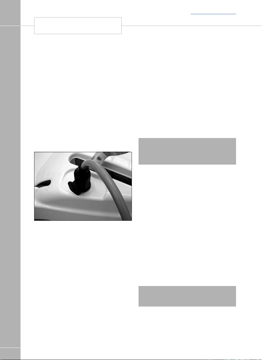
ELECTRICAL SYSTEM
Back to section menu
The electrical system
General Information
It is strongly advised that the mains installation
SERVICES
is inspected periodically to ensure safe
use. The IET (BS7671) wiring regulations
recommend that mains installations in touring
caravans are re-inspected every 3 years.
The National Caravan Council lists the
qualifications necessary to perform this
inspection, but an NICEIC approved contractor
is probably the first choice.
On arrival at the campsite
• Disconnect hitch and 13 pin plug from the
• Place the 13 pin plug in the holder provided
13 pin plug example
• Check the suitability of the supply, is it AC or
• Ensure that there is a proper earth
• If in doubt consult site staff.
• Make sure that the supply from the site is
• Make sure that the charger switch on the
• Lift the cover on the electricity inlet on the
• At the site supply point, connect the other
• Switch on the main switch at the site supply
52
towing vehicle.
to prevent damage.
DC, is the voltage and frequency correct.
(3 pin socket outlet).
switched off.
PSU is switched off.
caravan, and insert the connector on the
flexible supply cable.
end of the supply cable to this using the
socket provided.
point.
Care point: It is good practice to test the RCD
(Residual Current Device) in the PSU before
switching on. There is a test button on the
RCD to test the lever, put the lever in the up
position (on) before testing.
Care point: As with the RCD it is good
practice to check the Miniature Circuit Breaker
(MCB) in the PSU. Switch all to the on position
(lever up). If any do not stay up then there is
a fault.
On departure from the campsite
• Switch off supply from the site, disconnect
the cable at both ends.
• Switch off RCD.
! WARNING: Current consumption in the
caravan must not exceed 16 amps or the
pitch permitted maximum if this is less than
16 amps.
Overseas connection
• Connection to a mains voltage overseas
requires particular attention.
• Overseas supplies can be of
reverse polarity.
• Reverse polarity results in equipment not
necessarily being isolated when turned off,
reverse polarity indicator on the PSU will light
in the event of reverse polarity.
• The only sure way to make equipment safe is
to unplug it.
• It is useful to have a means of checking
polarity when overseas.
• If it can be achieved then connect live to live,
and neutral to neutral to achieve full electrical
protection.
! WARNING: Never allow modifications
or repairs of electrical or LPG systems and
appliances except by qualified persons.

Back to section menu
13 PIN CONNECTION
SERVICES
13 pin connection
When using the 13 pin connector system for
the first time it is worth taking a few minutes
to familiarise yourself with the basic features of
the connectors.
Fig. 1 - Correct
alignment
Fig. 2 - Incorrect
alignment
Fig. 3 - Incorrect
alignment
degrees clockwise until a click is felt or heard,
at this point the cover flap can be allowed to
fall over the circular surface of the plug top
(figs 6 & 7).
To remove the plug it is important to rotate the
outer body a full 90 degrees anti-clockwise,
again until a click is heard or felt before
withdrawing the plug from the socket. This will
ensure that the inner and outer parts of the
plug are returned to a locked condition.
If the connector is not fully rotated anticlockwise prior to removing it from the socket
it is possible that the inner ring will become
'floating' and may result in a condition where
the protrusion will be incorrectly aligned (see
fig 2 & 3).
If this situation does occur then it can be
corrected by inserting the edge of the
protrusion on the plug into the groove in the
socket (fig 8) and rotating the plug body anticlockwise until a click is felt. This process will
re-establish the lock between the inner and
outer parts allowing the correct insertion of the
plug into the socket.
Fig. 4 - Alignment
marks
The important difference with the new 13 pin
plug, when compared to the old 12N/S type,
is that the plug has an inner ring assembly that
is independent from the outer body. Under
normal circumstances the inner ring and the
outer body will be locked in one position (see
fig 1).
When the plug is first inserted in the socket
body ensure that the locating protrusion (key)
matches the groove (keyway) in the socket
body. The outer body can then rotated a full 90
Fig. 5 - Socket
body (containing
female socket
terminals) fitted to
the car
53

13 PIN CONNECTION
SERVICES
Fig. 6
Fig. 7
Back to section menu
230V mains electrical equipment
power consumption
Note: It is possible that the 230v mains
electrical equipment may not all operate
simultaneously. A typical UK site mains hook
up point provides a maximum output of 10
amps and on some continental sites the
available output may be as low as 5 amps.
If your loading exceeds the site supply it may
trip the site circuit breaker. Please check the
available mains supply with your site operator.
Similarly loadings on each circuit breaker within
the caravan should be observed.
A label positioned close to the MCB’s
(Miniature Circuit Breakers will identify which
appliances within the caravan are fed from
which MCB. Consulting the typical appliance
consumption figures table in conjunction
with this label, will give an indication of which
appliances can, and cannot, (site supply
allowing), be operated simultaneously.
54
Fig. 8
Plug inner ring
(containing
male pin
terminals fitted
to the caravan)
Plug outer
body with locating
groove and hood
fitted to the
caravan)
Fig.9

Back to section menu
WIRING OF CONNECTING CABLES AND
CARAVAN MAINS INLET
BLUE
NEUTRAL
TERMINALS
LIVE
PINS
BROWN
LIVE
EARTH
YELLOW & GREEN
VIEW OF
2
VIEW OF
SERVICES
PITCH SUPPLY
OUTLET
VIEW OF
TERMINALS
PINS
VIEW OF
VIEW OF
SOCKET TUBES
VIEW OF
TERMINALS
BLUE
NEUTRAL
LIVE
NEUTRAL NEUTRAL
LIVE
RED
LIVE
BLACK
NEUTRAL
BROWN
LIVE
EARTH EARTH
EARTH
YELLOW & GREEN
EARTH
GREEN &YELLOW
FLEXIBLE WIRING FIXED WIRING
FLEXIBLE 3 CORE CABLE 2.5mm
NEUTRAL BLACK
LIVE RED
NEUTRAL BLUE
LIVE BROWN
NEUTRAL NEUTRAL
EARTH EARTH
VIEW OF
SOCKET TUBES
LIVE
LIVE
BROWN
VIEW OF
TERMINALS
EARTH
GREEN &YELLOW
BLUE
NEUTRAL
CABLE COUPLER
EARTH GREEN & YELLOW
EARTH GREEN & YELLOW
Wiring of connecting cable and caravan mains inlet
The legal length of the mains inlet cable is 25 ± 2 metres. When in use it must be fully uncoiled and protected from traffic.
55

TYPICAL APPLIANCE CONSUMPTION FIGURES
SERVICES
Back to section menu
56
230 Volt 12 Volt LP Gas
Typical appliance consumption figures
Watts Amperes Watts Amperes grams/hour
Appliance/ Item
Dometic Refrigerator 190 W 0.8 amp Only when driving 16 g/h
Whale Space Heater 500 / 1000 / 2000 W 2.2 / 4.4 / 8.7 amp 20 W - 26.4 W 1.7 - 2.2 amp 150 g/h
Whale Water Heater 600 / 1200 W 2.6 / 5.2 amp 4 W 0.36 amp g/h
Hob burners Not applicable Not applicable 70 - 161 g/h
Grill Not applicable Not applicable 117 g/h
Battery Charger 690 W 3.0 amp Not applicable Not applicable
Omnivent Not applicable 2 w - 8.6 w 0.2 - 7.2 amp Not applicable
Not applicable 0.4W - 6.1W 0.05 - 0.5 amp Not applicable
12V LED Lights
(each, depending on size of light)
Pressure switched water pump Not applicable 48 W 4.0 amp Not applicable
Note: These are approximate figures for guidance only, and are subject to changes in specification. The figures show energy consumption
when an item or appliance is operating – i.e. a light is illuminated, or a heating system is providing space heating or water heating. Appliances
which feature LCD or illuminated control panels can have a low current consumption when in stand by mode, or have a constant low current
draw in the background to run their displays and electronic systems - these figures are typically 0.4 amps or less, for each applicable item.
These electronic items can in most cases be switched off individually, or, use of the System Shutdown button on the power supply unit isolates
all of these items.

Back to main menu
ELECTRICS
Swift Command Power Control System ................................................................................... 58
Control Panel Operation ........................................................................................................... 60
Residual Current Device & Miniature circuit breakers ................................................................ 63
Battery charger ........................................................................................................................ 64
Leisure Battery ......................................................................................................................... 64
12 Volt DC Fuses ..................................................................................................................... 66
System warnings ..................................................................................................................... 72
Remote access and control ...................................................................................................... 79
Battery .................................................................................................................................... 82
Solar panel connection point ................................................................................................... 83
Generator usage ...................................................................................................................... 84
Habitation relay ........................................................................................................................ 85
Exterior 230v socket ................................................................................................................ 85
ELECTRICS
57

Back to section menu
SWIFT COMMAND POWER CONTROL SYSTEM
ELECTRICS
ELECTRICS
ELECTRICS
1. Introduction
This section of the handbook will guide you
through the operation of the electrical system.
All details are correct at the time of going to
press. Please also see the online version which
will include any later updates or amendments.
Further technical details are contained in
section 3 or in the supporting technical manual
available from www.sargentltd.co.uk
For the safe operation of all electrical
equipment within your caravan it is important
that you read and fully understand these
instructions. If you are unsure of any point
please contact your dealer / distributor for
advice before use.
The system has a number of key components
that you will need to be familiar with before
attempting to use the system, these are:
· The EC601 or EC602 Power Supply Unit
(PSU) - a combined mains consumer unit and
12V controller located in the wardrobe.
• The EC620 Control Panel (CP) - a remotely
located user control panel used to turn
circuits on and off and to display battery,
water tank and other system information.
This panel uses simple straightforward
controls and reliable data communication to
the PSU.
• The PX300 Intelligent Battery charger 300W.
• The C44 Road Light Fuse Box - This small
unit is located in the front bed box. The unit
houses fuses for the road lighting circuits
and supplies from the tow vehicle, and also
has connectors for the optional alarm system
and Automatic Trailer Control (ATC) unit.
2. Using the System
2.1 Power Supply Unit - Component
Layout (see image above)
The PSU is located in the wardrobe.
2.2 Activating the System
The EC600 system has a shutdown feature
that can be used when the vehicle is in
storage. This allows the leisure electronics
to be turned off when not required to save
battery power. When in the off state the alarm
and tracking system supplies are still active, all
other supplies are turned off.
Before using the system please ensure the
system shutdown switch is in the on position
(button in) the system is now active.
Note: if you plan to use the Swift Command
remote features the system needs to be active.
58
58

Back to section menu
SWIFT COMMAND POWER CONTROL SYSTEM
ELECTRICS
ELECTRICS
2.3 Connecting to the Mains 230V supply
and Safety checks
For your safety it is IMPORTANT that you
follow these connections instructions each
time your Leisure Vehicle is connected to a
mains supply. This section assumes that the
system is complete and that a Leisure battery
has been installed (see 3.4).
A) Ensure suitability of the Mains Supply.
Your caravan should only be connected to an
approved supply that meets the requirements
of BS7671 or relevant harmonised standards.
In most cases the site warden will hold
information regarding suitability of supply. If
using a generator you also need to comply
with the requirements / instructions supplied
with the generator. Please note that some
electronic generators may not be compatible
with your leisure system. Further generator
operational information is contained elsewhere
in this manual.
B) Switch the PSU internal Power
Converter OFF.
Locate the green ‘Charger’ power switch on
the PSU and ensure the switch is in the off
position (button out) before connection to the
mains supply.
C) Connect the Hook-up Lead.
Firstly connect the supplied hook-up lead
(orange cable with blue connectors) to the
Leisure Vehicle and then connect to the mains
supply.
D) Check Residual Current Device
operation.
LLocate the RCD within the PSU and ensure
the RCD is switched on (lever in up position).
Press the ‘Test’ button and confirm that the
RCD turns off (lever in down position). Switch
the RCD back to the on position (lever in up
position). If the test button failed to operate the
RCD see section 3.18.
E) Check Miniature Circuit Breakers
LLocate the MCB’s within the PSU (adjacent to
the RCD) and ensure they are all in the on (up)
position. If any MCB’s fail to ‘latch’ in the on
position see section 3.18.
F) Turn the PSU ON.
Locate the black ‘Shutdown’ button and
ensure it is in the on position (press button in).
Locate the green ‘Charger’ switch on the PSU
and turn to the on position (press button in).
The charger switch will illuminate when turned
on.
G) Check correct Polarity.
Locate the ‘Reverse polarity’ indicator on the
PSU and ensure that the indicator is NOT
illuminated. If the indicator is illuminated see
section 3.18.
H) Check operation of equipment.
It is now safe to operate the 12V and 230V
equipment.
59
59

Back to section menu
SWIFT COMMAND POWER CONTROL SYSTEM
2.4 Control Panel - Component Layout (see image below)
Your control panel will have an appearance as below, but depending on your vehicle specification
the control panel features will vary. Not all features are present in all vehicles.
ELECTRICS
ELECTRICS
2.5 Control Panel Operation
ELECTRICS
Power Button. Press the power button to turn the leisure power on. Press
the button again to turn the power off. The adjacent LED will illuminate
when the power is on, the screen backlight will turn on and system
information will be shown on the LCD display. To avoid night time nuisance
the LED and backlight will be turned off after a preset time, see note below.
60
60
Menu Navigation Up Button. Use the menu up and down buttons to
scroll through the various functions. The menu operates on a continuous
loop arrangement so you can go up or down to reach all menu items. It is
recommended to start in the down direction.
Menu Navigation Select Button. Use the select button make a selection
or to change a value or setting. This button is also used to select the
display or toggle the display information on many menu items.
Menu Navigation Down Button. Use the menu up and down buttons to
scroll through the various functions. The menu operates on a continuous
loop arrangement so you can go up or down to reach all menu items. It is
recommended to start in the down direction.

Menu
Tree
Back to section menu
SWIFT COMMAND POWER CONTROL SYSTEM
• Leisure battery, the leisure battery voltage and charging or discharging
current is displayed. Use the select button to toggle the display, with
voltage on the main display whilst current (in or out of the battery is
shown on the bar-graph and vice versa, current on the main display and
voltage on the bar-graph.
• Vehicle battery, when connected the vehicle battery voltage and
charging or discharging current is displayed. Use the select button to
toggle the display, with voltage on the main display whilst current (in or
out of the battery is shown on the bar-graph and vice-versa, current on
the main display and voltage on the bar-graph.
• Solar Power, the charging current from the solar panel along with the
voltage of the battery it is charging is displayed. Use the select button
to toggle the display, with voltage on the main display whilst current is
shown on the bar-graph and vice-versa, current on the main display and
voltage on the bar-graph.
• Select Battery, press the select button toggles between the Leisure
and Vehicle batteries as the power source (or battery to be charged). The
selected battery is shown in the header area.
• Tank-Fill on/off, Turn tank fill on to start the external water pump and to
start transferring water from the external water container to the internal
water tank. Tank filling will stop when the onboard tank is full or if more
than 7 minutes have elapsed.
• AC Limit, the AC current limiter, when enabled, will monitor the incoming
AC current and if the set limit is reached the 230V heating element
within the heating system will be temporarily turned off until the current
falls below the set limit. Use the select button to set the limit or to turn
the feature off. The AC Limit icon in the header indicated that a limit is
set and will flash if the limiter is active. For this feature to work correctly
the Heating setting must be set to Timer so that the EC600 system can
control the heating system.
• Temperature & Humidity, Pressing the select button scrolls through the
internal temperature, internal humidity & external temperature readings.
Please note that due to the location of the internal temperature sensor
there may be slight differences to the temperature shown on the heating
system. Further details can be found in section 3.18.
• Dimmer %, this display shows the lighting dimming level and is adjusted
in 5% increments. The display commences where the level was last set.
Press the select button to increase the level up to 100% and then back
down again to 5%. Pressing the dimming button on the control panel
immediately shows this dimming value.
• Heater Settings, this sub menu allow the heater controls and associated
settings to be adjusted. A full explanation of the controls can be found in
the heater section.
• Air Conditioning Settings, this sub menu allow the optional air-
conditioning controls and associated settings to be adjusted. A full
explanation of the controls can be found in the aircon section.
• Fridge Settings, this sub menu allow the fridge controls and associated
settings to be adjusted. A full explanation of the controls can be found in
the fridge section.
• System Settings, this sub menu allows a number of system features to
be configured like the Clock, Date, Key beep, Backlight time, LED time,
Tank Alarms, Bluetooth Pairing etc.
ELECTRICS
ELECTRICS
61
61

Back to section menu
SWIFT COMMAND POWER CONTROL SYSTEM
ELECTRICS
ELECTRICS
Note, display illumination. The LCD back
light will illuminate for the pre-set time (default
time is 30 seconds) adjustable between 5 and
120 seconds. Setting the timer to 0 seconds
will force the backlight to be permanently on.
The illumination of the blue LED’s adjacent
to the power, pump & awning light buttons
can be configured in the same way as the
backlight. The screen will wake up if your
hand is placed near the panel or if a button is
pressed.
ELECTRICS
Pump Button. With the power on, press the pump button to turn the water
pump on. Press the button again to turn the pump off. The adjacent LED
will illuminate when the pump is on and the level of the water tank will be
shown on the screen.
Interior Lights Button. With the power on, press the lights button to turn
the main lighting supply on or off.
Light Dimming Button. With the power on, press the dimmer button to
turn the dimmed lighting on or off. Press the select button to adjust the
dimmer level (the menu automatically changes to the adjustment screen).
The last setting is remembered.
Awning Light Button. With the power on, press the awning light button to
turn the awning light on or off. The Adjacent LED will illuminate when the
awning light is on. The awning light may also be controlled by the caravan
alarm system.
2.6 Operation while driving
The EC600 system is designed to shutdown
parts of the system while the engine is running.
This is to meet Electro Magnetic Compatibility
(EMC) regulations and to ensure the safe
operation of the caravan.
Please ensure the system shutdown switch on
the PSU is in the on (button in) position before
driving (see 2.2). This will ensure the electronic
system is active and will therefore be able
to control the charging process, supply the
refrigerator and monitor other system circuits.
With the engine running the screen will show
ENGINE RUNNING, the leisure and vehicle
battery icons will be displayed to indicate they
are being charged and the charging voltage
will be show in the main display.
62
62

Back to section menu
SWIFT COMMAND POWER CONTROL SYSTEM
ELECTRICS
ELECTRICS
3 System Technical Information
The following section provides further technical
information relating to the electrical system.
You can also access the supporting technical
manual from www.sargentltd.co.uk
3.1 Residual Current Device & Miniature
Circuit Breakers
The Residual Current Device (RCD) is
basically provided to protect the user from
lethal electric shock. The RCD will turn off
(trip) if the current flowing in the live
conductor does not fully return down the
neutral conductor, i.e. some current is
passing through a person down to earth or
through a faulty appliance. To ensure the RCD
is working correctly, the test button should be
operated each time the vehicle is connected to
the mains supply (see section 2.3)
The Miniature Circuit Breakers (MCB’s)
operate in a similar way to traditional fuses
and are provided to protect the wiring
installation from overload or short circuit.
If an overload occurs the MCB will switch
off the supply. If this occurs you should
investigate the cause of the fault before
switching the MCB back on.
3.2 Generator Usage
Caution should be used before connecting a
generator to your caravan.
! WARNING: Never start or stop
the generator while electrical loads are
connected and switched on. Start the
engine, let it stabilise and then connect
the electrical load. To stop the engine,
disconnect the electrical load and let
engine stabilise before switching off
Whilst some generators use electronic inverter
technology, others use a more basic principle
to generate the 230V supply. Preference
should be to choose a generator which
produces a consistent sinusoidal wave form
with accurate voltage control.
The Reverse Polarity warning light on the
PSU may illuminate when using a Generator.
This is a normal side effect when using some
types of generator. Instead of connecting the
neutral conductor to earth, some generators
centre tap the earth connection making both
neutral and live conductors 110V above earth.
This 110V difference causes the neon polarity
indicator to illuminate.
In most cases it is safe to use a generator, but
please consult the generator handbook for
further information.
The following table shows the rating and circuit
allocation for the three MCB’s
MCB Rating Output Wire Colour Description
1 10 Amps White 230V Sockets
2 16 Amps White (Yellow for heater) Extra 230V Sockets / Heating System
3 10 Amps Black (Blue for Whale
water heater)
Fridge / Charger / Auxiliary devices /
Whale Water Heater
63
63

Back to section menu
SWIFT COMMAND POWER CONTROL SYSTEM
3.3 Battery Charger
During stage 1 the battery voltage is increased
gradually while the current is limited to start the
charging process and protect the battery. At
ELECTRICS
ELECTRICS
stage 2 the voltage rises to 14.4V to deliver the
bulk charge to the battery. When the battery
is charged, the voltage is decreased at stage
3 to 13.6V to deliver a float charge to maintain
the battery in the fully charged state. The
charger can be left switched on continuously
as required.
The battery charger / power converter also
provides power to the leisure equipment when
the mains supply is connected. This module
supplies DC to the leisure equipment up to a
maximum of 25 Amps (300 Watts), therefore
the available power is distributed between
the leisure load and the battery, with the
leisure load taking priority as per the following
example:
Leisure
Load
5A 20A
10A 15A
15A 10A
20A 5A
ELECTRICS
Available power for battery
charging
! WARNING: Under heavy loads the
Battery Charger case may become hot.
ALWAYS ensure the ventilation slots have
a clear flow of air. Do not place combustible
materials against / adjacent to the charger.
3.4 Leisure Battery
A) Type / Selection
For optimum performance and safety it
is essential that only a proprietary brand
LEISURE battery is used and it is suggested
to select a battery from the NCC Verified
Battery Scheme with a typical capacity of 75
to 120 Ah (Ampere / hours). Depending on
the prospective use of the caravan the correct
type should be selected (A, B or C). A normal
car battery is NOT suitable. This battery should
always be connected when the system is in
use.
The PSU is configured to work with standard
lead acid leisure batteries, and in most cases
is also compatible with the latest range of
Absorbed Glass Matt (AGM) batteries. Before
fitting non-standard batteries please check
that the charging profile described in 3.3 is
suitable for the type of battery by referring
to the battery documentation or battery
manufacturer.
Some vehicle installations can cater for two
leisure batteries connected in parallel. In these
cases it is recommended that two identical
batteries are used. The battery feed is fitted
with an inline fuse between the battery and
the electrical harness, and is usually located
immediately outside the battery compartment
or within 500mm of the battery. The maximum
rating of this fuse is 20A per battery.
B) Installation & Removal
Always disconnect the 230V mains supply
and turn the PSU green charger switch to the
off position (button out) before removing or
installing the battery.
When connecting the battery, ensure that the
correct polarity is observed (black is negative
[-] and red is positive [+]) and that the terminals
are securely fastened. Crocodile clips must not
be used.
! WARNING: Explosive gases may be
present at the battery. Take care to prevent
flames and sparks in the vicinity of
the battery and do not smoke.
64
64

SWIFT COMMAND POWER CONTROL SYSTEM
C) Operation / Servicing
Under normal circumstances it should not
be necessary to remove the battery other
than for routine inspection of the terminals
and “topping up” of the battery fluid where
applicable. Please see instructions supplied
with the battery.
Note: Do not over discharge the battery.
One of the most common causes of
battery failure is when the battery is
discharged below the recommended level of
approximately 10V. Discharging a battery
below this figure can cause permanent
damage to one or more of the cells within
the battery.
To prevent over discharge, the EC600 system
incorporates a battery protect circuit that
warns the users and then disconnects the
batteries when they fall below set values.
If a warning is active a beep will be emitted
by the control panel and information will be
shown on the screen. To cancel the warning,
press the select button. These warnings will
not be repeated unless the power switch is
turned off and on again. This is to ensure the
warning does not become a nuisance.
Back to section menu
ELECTRICS
ELECTRICS
Battery Voltage
cut off
Vehicle 10.9V Battery selection
Leisure 9V Power is turned
Action after
cut off
is changed from
Vehicle battery to
Leisure battery. If
the leisure battery
is below 9V then
a further warning
will occur (see
below).
off
Notes
This cut off level is designed to protect the vehicle
battery from over discharge. The 10.9V level
ensures there is sufficient power in the battery to
run the vehicle electronics and start the vehicle.
This cut off only applies to power drawn from the
battery by the leisure equipment; it will not protect
the battery if you leave vehicle circuits switched on,
such as the road lights.
This is an emergency cut off level to protect the
battery from severe damage. You should not rely
on this cut off level during normal operation, but
manage your power consumption to a discharge
level of about 11.5V.
This cut off only applies to power drawn from the
battery by the leisure equipment that is controlled
by the control panel power switch; it will not
protect the battery from discharge by permanently
connected equipment.
65
65

Back to section menu
SWIFT COMMAND POWER CONTROL SYSTEM
3.5 12 Volt DC Fuses
! WARNING: When replacing fuses always
ELECTRICS
ELECTRICS
replace a fuse with the correct value. NEVER
replace with a higher value /
rating as this could damage the wiring
harness. If a replacement fuse ‘blows’
do not keep replacing the fuse as you
could damage the wiring harness. Please
investigate the fault and contact your dealer.
Fuse Rating Fuse Colour Description
1 25 Amps White Charger
2 7.5 Amps Brown Permanent 12V / Alarm / Fridge Electronics / Alde Heating
3 10 Amps Red 12V Sockets / TV Amplifier / Radio
4 10 Amps Red Extractor Fans / Truma Heating / Whale Space Heater
5 5 Amps Tan Appliances / Hob Ignition / Toilet / Whale Water Heater
6 10 Amps Red Water Pumps
7 7.5 Amps Brown Lighting, Main Lights & Dim Channel 1.
8 5 Amps Tan Lighting, Entry Light & Dim Channel 2.
9 10 Amps Red Spare Outputs / Marker Light
10 10 Amps Red Auxiliary / Awning Light
ELECTRICS
66
66
Note: Fuses (2-13) have a Red LED below
them which provides indication that the fuse
has blown. The charger fuse has a green
LED which Indicates that the charger is
working.
The following table shows details of the fuse(s)
located at the Leisure battery. See also 3.4A
Fuse Rating Fuse
Battery 1 20
Amps
Battery 2 20
Amps
Colour
Yellow Fuse remotely located near battery
Yellow Fuse remotely located near battery 2 (where fitted)
Description

SWIFT COMMAND POWER CONTROL SYSTEM
The following table shows details of the fuse(s)
located at the Road Light fuse box.
Fuse Rating Fuse Colour Description
1 20 Amps Yellow Fridge Supply
2 5 Amps Tan Left Hand Tail Lights
3 5 Amps Tan Right Hand Indicators
4 5 Amps Tan Fog Lights
5 - - Not fitted
6 20 Amps Yellow Car Battery Supply
7 5 Amps Ta n Right Hand Tail Lights
8 5 Amps Ta n Left Hand Indicators
9 7.5 Amps Brown Stop Lights
10 5 Amps Tan Reverse Lights
Back to section menu
ELECTRICS
ELECTRICS
3.6 Solar Charge Management
The EC601/602 PSU incorporates a built-in
solar charge management feature, which will
monitor the input from a separate solar panel
and regulator. The Solar Active symbol will be
displayed on the control panel when there is
an amount of energy available to charge the
battery. The voltage and current produced
from the regulator can be viewed on the multifunction display by selecting the Solar Power
menu item.
3.7 Water Pump Operation
The EC620 control panel pump button
operates the internal water pump drawing
water from an internal tank if fitted, or an
external container when no internal tank is
fitted.
The system incorporates an automatic tank fill
feature. When turned on this will automatically
fill the onboard water tank from the external
container and will switch off automatically
when full. To enable tank fill, select ‘Tank-fill on’
on the control panel. To ensure the external
pump is not damaged if the external tank
runs dry, the pump runs for a maximum of 7
minutes.
The water tanks (fresh & waste) incorporate a
level warning feature to warn the user when
the fresh water level drops below 25% or when
the waste water level reaches 100%.
If the water pump power is turned on and
the fresh water level drops to below 25% a
warning beep will be heard and a message will
be displayed on the control panel. To cancel
the warning, press the select button.
If the water pump power is turned on and the
waste water level rises to full (100%) a warning
beep will be heard and a message will be
displayed on the control panel. To cancel the
warning, press the select button.
These warnings will not be repeated unless the
water pump power switch is turned off and on
again.
This is to ensure the warning does not become
a nuisance.
67
67

Back to section menu
SWIFT COMMAND POWER CONTROL SYSTEM
3.08 AC Current Limiter Operation
The EC600 system features a 230V current
monitoring system which allows the mains
hook up current to be displayed on the control
ELECTRICS
ELECTRICS
panel. The resolution of this reading is 0.5A.
A current limit setting can be activated which
if reached will switch off the electric elements
in the heating system, until such time as
the current drops and the elements will be
switched back on. An example of this is if a
kettle was to be operated whilst the heating
was on and the current limit was reached
then the heater electric element would be
temporarily switched off, when the kettle
had boiled then the heater element would be
switched back on automatically.
This feature is particularly useful when abroad
on a low current supply. A warning that the
limit has been reached is displayed on the
control panel.
Setting the value to OFF will disable this
feature.
The Swift Command App can be used to
adjust this feature.
ELECTRICS
3.09 Lighting & Dimming Operation
The system contains up to two dimming
channels for groups of lights which can be
controlled by the dimmer button. Some
motorhome models also feature an additional
furniture mounted dimming control.
The awning light can be controlled by a
number of items within the caravan, the local
switch adjacent to the entry door, the alarm
system lighting button, the control panel
awning light button and the App.
Each item can toggle the light on and off.
The Swift Command App can be used to both
configure and adjust the lighting and dimming.
68
68

Back to section menu
SWIFT COMMAND POWER CONTROL SYSTEM
3.10 Heating Controls
There are a number of heating systems that can be controlled by the EC600. The system will
be preconfigured by the manufacturer or supplying dealer. The following menu items are only
available in Timer control mode, and 3 examples are shown for the different heating system
variants.
Scroll to the Heating Settings and press select to set or adjust the following items:
WHALE
Menu Item Description
Control
The following menu items are only available when in Timer control mode.
WH Energy
AH Energy
Timer 1
T1 Heating
T1 H/Water
The menu now repeats for timer 2 through to timer 4
Exit
settings?
Set to MANUAL to use the controls supplied by the heating
appliance manufacturer
Set to TIMER to control the appliance by the control panel with the
settings below
Set to APP control the appliance by the Swift Command app
Set the energy setting to OFF, GAS, EL1, EL2, MIX1 or MIX2. See the water
heater user manual for a description of these settings.
Set the energy setting to OFF, FAN, GAS, EL1, EL2 or EL3. See the air heater
user manual for a description of these settings.
Set the timer 1 event time.
This setting adjusts in 15 minute increments and
uses the 24 hour clock.
Set the timer 1 heating temperature.
This setting can be off, or 5 through to
30 degrees C.
Set the timer 1 hot water temperature
This setting can be OFF or ON
When timer 4 is completed the exit settings item is reached. Press the select
button to exit and save the settings.
Example 07:30
Example 22 deg C
Example Eco
ELECTRICS
ELECTRICS
The timer example above will set the heating to 22 degrees C and the hot water to eco at 7:30
in the morning.
69
69

Back to section menu
SWIFT COMMAND POWER CONTROL SYSTEM
3.11 Refrigerator Controls
The main refrigerator settings can be set /
controlled by the EC620 control panel or the
Swift Command app. These controls work
ELECTRICS
ELECTRICS
in parallel with the ones on the fridge control
panel, so the settings can be changed by
either method.
Scroll to the Fridge Settings and press select
to set or adjust the following items:
Menu Item Description
Mode
Setting Set the required cooling setting. Available options are;
Status Here you can view the cooling status. If you have just changed the above
ELECTRICS
Dometic Refrigerators / Fridge Freezers
Set the required operating mode. Available options are;
OFF
AUTO
GAS
12V DC
230VAC
The default setting when the system is first turned on is OFF.
1 (minimum)
2
3 (middle)
4
5 (maximum)
The default setting when the system is first turned on is 1.
cooling setting then you should allow at least 15 minutes for the setting to take
effect and update the reported status.
The possible statuses are;
Too Cold {suggest reducing the setting}
Cold (--) {suggest reducing the setting}
Cold (-)
Optimal
Warm (+)
Warm (++) {suggest increasing the setting}
Too Warm {suggest increasing the setting}
70
70
When viewing the Fridge Settings menu item
the large digit on the screen shows the current
cooling setting (1 to 5).

Back to section menu
SWIFT COMMAND POWER CONTROL SYSTEM
ELECTRICS
ELECTRICS
3.12 Air-conditioning
If your vehicle has been fitted with a
compatible air-conditioning unit then the
settings can be set / controlled by the EC620
control panel or the Swift Command app.
Scroll to the Aircon Settings and press select
to set or adjust the related settings.
Aircon features are currently being finalised, so
further information will appear here in version
2.3 of this document.
3.13 Other Controls
The main control panel will display the software
version number of both the Control Panel and
the PSU. On the EC620 menu item press the
select button to display software information.
3.14 AL-KO ATC Operation
On caravans fitted with AL-KO Automatic
Traction Control, the Swift Command App can
be used to monitor the status of the ATC from
within your tow vehicle. More information on
this can be found within the Swift Command
App and the associated user guide.
3.15 Temperature Readings
The EC600 Temperature sensor measures the
‘core’ temperature of the vehicle, and provides
a figure for information only. The same sensor
also measures humidity, providing a figure (also
for information only) from within that bed box
or storage area.
It is hoped that the temperature information is
a particularly useful figure, for instance when
checking on the vehicle remotely during cold
weather.
For vehicles fitted with Alde or Truma heating
systems, this sensor is not used to control the
heating temperature as it is measured above
the door by the Alde or Truma room sensor.
The readings on the heating system may vary
relative to the storage area temperature below
the bed.
For vehicles fitted with a Whale heating
system, the sensor is used to control the
heating temperature as this system does not
have its own sensor.
Heat from other items in the vehicle (in
particular components from the heating
system itself) will have a bearing on the reading
displayed by the Swift Command system.
Ventilation is also present in the majority of bed
/ storage areas, and air entering or passing
through this area will also have an effect on the
temperatures and humidity levels displayed.
3.16 Bluetooth Pairing
Using the control panel, access the System
Settings menu and then scroll to the Bluetooth
pairing section. Press the select button to
start pairing, the power button LED will flash
to indicate the pairing mode. You can now
pair your device to the system following the
devices instructions to add a Bluetooth item.
Pairing remains on for 1 minute and is then
turned off automatically.
Note: Further help with Bluetooth pairing is
available in the form of a help video which
can be viewed on the Sargent website in the
Support Information section.
71
71

Back to section menu
SYSTEM WARNINGS
3.17 System Warnings
The system incorporates a number of warnings that are active at specific times. These are
summarised below, and also covered by relevant sections of this manual. When a warning is active a
triangle will be displayed in the control panel header area.
ELECTRICS
ELECTRICS
Warning When Type
Fresh water level
low
Leisure battery
voltage low
Leisure battery
voltage high
Vehicle battery
warnings
Engine running When the engine is started the
Mains lead
(hook-up cable)
still connected /
plugged in
With pump turned on and fresh
water level low (less than 25%
full). Only available when an onboard tank is fitted.
With control panel power on and
leisure battery selected (as active
battery) and the voltage level falls
below 10V
With control panel power on and
leisure battery selected (as active
battery) and the voltage level is
below 9V
Note: This is an emergency cut off level to protect the battery from severe
damage. You should not rely on this cut off level during normal operation,
but manage your power consumption to a discharge level of 11.5V or
above.
This cut off only applies to power drawn from the battery by the leisure
equipment that is controlled by the control panel power switch; it will not
protect the battery from discharge by permanently connected equipment.
With control panel power on or
off and leisure battery is selected
(as active battery) and the
voltage level rises above 15V.
If the vehicle battery is selected instead of the leisure battery, with the
towing vehicle connected, then similar warnings to those described above
are applied to the vehicle battery. The vehicle battery low warning level is
10.9V
system power will be turned off.
When the engine is started and
the mains cable is still plugged in
and the charger is switched on.
Message on screen and 30 second
audible beep.
Message on screen and 30 second
audible beep.
Message on screen and 30 second
audible beep. If no action taken after
30 seconds then the system will
switch the power off to prevent severe
discharge of the battery
Message on screen and repeated
beeps from the control panel. The
power is automatically turned off. The
beeping will not stop until the fault is
cleared.
Message on screen, Leisure & Vehicle
battery symbols indicating both
batteries are connected for charging.
The charging voltage is also shown on
screen.
Message on screen and repeated
beeps from the control panel. The
beeping will not stop until the hook-up
lead is removed.
72
72
Fault Possible Cause Proposed Fix
Heating
system
Refrigerator
/ Fridge
Freezer
When set to
control the heating
system, the
EC620 control
panel will show
related heating
system warnings
When set to
control the
refrigerator, the
EC620 control
panel will show
related warnings
Message on screen and 30 second audible beep.
Additional descriptive information is available when using
the Swift Command App.
Message on screen and 30 second audible beep.
Additional descriptive information is available when using
the Swift Command App.
Back to section menu
SYSTEM WARNINGS
ELECTRICS
ELECTRICS
73
73
SYSTEM WARNINGS
3.18 Common Fault Table
No 230 volt
ELECTRICS
ELECTRICS
output from
PSU
Reverse
Polarity light
is illuminated
on PSU
Back to section menu
Connecting lead
between the site
and Leisure Vehicle
not connected
RCD switched off Reset RCD as per 2.3D
RCD not operating
correctly
MCB switched off Reset MCB by switching OFF (down position) then back
No or deficient
supply from site
Other fault Contact your Dealer
Mains Supply
reversed?
Generator being
used
Check and connect lead as per 2.3C
Check supply polarity; if the RCD continues to fail contact
your Dealer as there is probably an equipment or wiring
fault.
ON (up position), if the MCB continues to fail contact your
Dealer as there is probably an equipment or wiring fault.
Contact site Warden for assistance
The reverse polarity light is designed to illuminate when
the Live and Neutral supply has been reversed / crossed
over. If the light illuminates there is a problem with the site
supply or the cable connecting the supply to your vehicle.
The light is designed to work on UK electrical supplies
(where the neutral conductor is connected to earth at
the sub station). If you are using your vehicle outside the
UK this light may illuminate when no fault exists. In these
cases consult the site warden for advice.
‘The Reverse Polarity warning light is on when using my
Generator’. This is a normal side effect when using some
types of generator. Instead of connecting the neutral
conductor to earth, some generators centre tap the earth
connection making both neutral and live conductors 110V
above earth. This 110V difference causes the neon polarity
indicator to illuminate. In most cases it is still safe to use
the generator, but please consult the generator handbook
for further information.
74
74

Fault Possible Cause Proposed Fix
Control Panel
Problems
Control Panel has
no display
12V Power turns
off
Control Panel
locked / erratic
function
Check batteries and fuses, turn PSU isolate switch and
charger switch on and ensure mains supply is connected.
Check control panel connecting lead at PSU and behind
Control Panel Contact your Dealer
Battery protect feature has operated to protect the Vehicle
battery and or the Leisure battery. See 3.4C Over voltage
protection has been activated, the control panel will
display a warning. A number of things can cause this but
the most common is the solar panel, it is worth checking
the regulator is connected correctly and operating
within the correct parameters. Engine has been started,
all equipment has been disconnected to meet EMC
requirements. See 2.6
Observe control panel handling instructions Control panel
software may have crashed. Reboot control panel by
turning off the PSU isolate switch. Wait 30 seconds then
turn the switch back on. Check with your dealer that your
system has the latest software installed, as an update may
be available.
Back to section menu
SYSTEM WARNINGS
ELECTRICS
ELECTRICS
75
75

SYSTEM WARNINGS
3.19 Common Fault Table
Fault Possible Cause Proposed Fix
ELECTRICS
ELECTRICS
No 230 volt
output from PSU
Reverse Polarity
light is illuminated
on PSU
Back to section menu
Connecting lead
between the
site and Leisure
Vehicle not
connected
RCD switched off Reset RCD as per 2.3D
RCD not
operating
correctly
MCB switched off Reset MCB by switching OFF (down position)
No or deficient
supply from site
Other fault Contact your Dealer
Mains Supply
reversed?
Generator being
used
Check and connect lead as per 2.3C
Check supply polarity; if the RCD continues to
fail contact your Dealer as there is probably an
equipment or wiring fault.
then back ON (up position), if the MCB continues
to fail contact your Dealer as there is probably an
equipment or wiring fault.
Contact site Warden for assistance
The reverse polarity light is designed to illuminate
when the Live and Neutral supply has been reversed
/ crossed over. If the light illuminates there is a
problem with the site supply or the cable connecting
the supply to your vehicle. The light is designed to
work on UK electrical supplies (where the neutral
conductor is connected to earth at the sub station).
If you are using your vehicle outside the UK this light
may illuminate when no fault exists. In these cases
consult the site warden for advice.
‘The Reverse Polarity warning light is on when
using my Generator’. This is a normal side effect
when using some types of generator. Instead of
connecting the neutral conductor to earth, some
generators centre tap the earth connection making
both neutral and live conductors 110V above earth.
This 110V difference causes the neon polarity
indicator to illuminate. In most cases it is still safe to
use the generator, but please consult the generator
handbook for further information.
76
76

Fault Possible Cause Proposed Fix
Control Panel
Problems
No 12 volt output
from PSU
Control Panel has
no display
12V Power turns
off
Control Panel
locked / erratic
function
No 230V supply Check all above
Charger not
switched on
Battery not
connected and /
or charged
Power button on
control panel not
switched to on
Battery flat /
Battery fuse
blown
Fuse blown Check all fuses are intact and the correct value fuse
Equipment
switched off /
unplugged
Other fault Contact your Dealer
Check batteries and fuses, turn PSU isolate switch
and charger switch on and ensure mains supply is
connected. Check control panel connecting lead at
PSU and behind Control Panel Contact your Dealer
Battery protect feature has operated to protect the
Vehicle battery and or the Leisure battery. See 3.4C
Over voltage protection has been activated, the
control panel will display a warning. A number of
things can cause this but the most common is the
solar panel, it is worth checking the regulator is
connected correctly and operating within the correct
parameters. Engine has been started, all equipment
has been disconnected to meet EMC requirements.
See 2.6
Observe control panel handling instructions. Control
panel software may have crashed. Reboot control
panel by turning off the PSU isolate switch. Wait 30
seconds then turn the switch back on.
Turn charger switch on, switch will illuminate
Install charged battery as per 3.4
Turn power on at control panel
Recharge battery, check fuses, check charging
voltage is present at battery
is installed as per fuse table
Check equipment is switched on and connected to
the 12V supply
Back to section menu
SYSTEM WARNINGS
ELECTRICS
ELECTRICS
77
77

SYSTEM WARNINGS
Fault Possible Cause Proposed Fix
Pump not
ELECTRICS
working
Back to section menu
Fuse blown Replace fuse with correct value as per fuse table.
Pump turned off Turn pump on by pressing the pump button at the
Setting incorrect
control panel.
Both the internal and external pump feeds are
controlled from the control panel. To alter the setting
of the pump switch see section 3.8. Ensure the
setting matches your desired requirement.
Lights not
working
Bluetooth
Communications
not working
Remote
Communications
not working
Fuse/s blown Replace fuse with correct value as per fuse table.
Lights turned off Turn Lights on by pressing the lights button, use
Bluetooth not
paired
Bluetooth not
active on Device
Bluetooth out of
range
Bluetooth
connection issue
Account details
not entered on
App
Account not
registered at time
of vehicle delivery
dimmer at the control panel.
Using System Settings menu, select Bluetooth Pair
option
Ensure that the handheld device has Bluetooth
switched on and that the device supports the
Bluetooth 4 standard (BLE)
Ensure the handheld device is within 7M of the
middle of the caravan/motorhome switch see
section 3.8. Ensure the setting matches your desired
requirement.
See App user guide for further details
Enter details in Account page of App settings menu
Check with supplying dealer or Sargent Electrical that
an account has been registered.
78

Back to section menu
REMOTE ACCESS & CONTROL
ELECTRICS
3.20 Contact details
Sargent Electrical Services Limited provide a
technical help line during office hours. Please
contact 01482 678981 if you require technical
help. For out of hour support please refer to
the support section of the Sargent web site
www.sargentltd.co.uk
4 Remote Access & Control
4.1 Swift Command App
The Swift Command app can be down loaded
from the Apple App Store or the Android Play
store.
A separate Swift Command User Guide is
available which covers the operation of the
app.
Before you can use the App with your
caravan or motorhome you will need to
create an account and sign up to the free
communication service. This is a simple
process and will be explained further by your
dealer at the vehicle handover.
Additional information is available at
www.swiftcommand.co.uk
4.2 Swift Command Web usage &
Description
In addition to the mobile App, you can also use
the same account and login details to access
the Swift Command web site.
Here you can update and amend your details,
look at location information and history, review
system information and historical data as
well as changing some system options and
settings.
4.3 Swift Command SIM Coverage &
Usage information
The EC600 system contains Mobile SIM with
36 month contract, which commences upon
activation at the Dealership when your vehicle
is linked to your account.
Below is a list of the countries covered by the
SIM under a fair usage policy, a complete list is
available at request.
Austria, Belgium, Bulgaria, Cyprus, Czech
Republic, Denmark, Estonia, Finland,
France, Germany, Greece, Hungary, Iceland,
Ireland, Italy, Latvia, Liechtenstein, Lithuania,
Luxembourg, Netherlands, Malta, Norway,
Poland, Portugal, Romania, Slovakia, Slovenia,
Spain, Sweden, United Kingdom.
For vehicles shipping direct to Australia or
New Zealand a special world-wide SIM is
fitted at the Swift factory. Please note that if
a UK specification vehicle is shipped to these
countries the remote features will not operate.
4.4 Replacement parts
The Control panel contains a small lithium
battery to maintain the clock when no other
energy supplies are available this will last in
excess of 5 years under normal conditions.
The battery is a CR2032 3.0V
The EC635 Communication module contains a
special backup battery pack which should last
in excess of 3 years under normal conditions.
The pack part number is 16308 available from
Sargent.
4.5 Updates
From time to time there may be updates to the
system firmware; these updates will be done at
service intervals by your dealership.
79
5 Technical Data & Approvals
5.1 Equipment – EC601, EC602, EC651, EC620, EC630 & PX300 Control Equipment
ELECTRICS
80
Outline Specification
INPUT 230V 230 Volts / 0 to 16 Amps + / - 10%
OUTPUT 230V RCD protected, 2 x MCB outputs of 10A &
INPUT 12V 2 x 20A battery inputs via 2 x 4 way
SOLAR INPUT 1 x Dedicated solar panel input (20 to 150W
OUTPUT 12V 25A total output via multiple switched channels
Integrated
CHARGER
Signal INPUT 4 x Fresh water level, 4 x Waste water level,
Data IN / OUT CANBUS Data communication and power to
IP rating IP31
Operating
temperature
Dimensions
EC601 & EC651
PSU
EC620 Control
Panel
EC630 Comms
Module
EC640 Sensor Overall size (HxWxD) 60 x 27 x 14mm Weight 80g
TECHNICAL DATA AND APPROVALS
1 x MCB output of 16A
Separate switched channels for heating
system and charger
connectors
panel) via a 2 way connector
protected by 13 fused outputs
Input 220-240 Volts AC +/- 10%, Frequency
50 Hz +/- 6%, Current 3A max.
DC Output 13.6 to 14.4 Volts nominal,
Current 25 Amps max (300 Watts).
1 x Engine running, plus multiple vehicle
connections, sensor inputs for temperature &
humidity
Control Panel via 6 way connector
CI-Bus Data communication to CI-Bus enabled
devices via RJ11/12 connector
Ambient 0 to 35° Celsius
Charger case temperature with full load
65° C Max
Overall size (HxWxD) 180 x 305 x 135mm
Clearances 75mm above, 50mm left & right
Overall size (HxWxD) 93 x 180 x 32mm
Cut-out size (HxW) 82 x 165mm
Overall size (HxWxD) 55 x 116 x 85mm Weight 550g
Back to section menu
Fresh water negative
sensed
Waste water negative
sensed
Automatic shutdown
and restart if
overheated /
overloaded
Weight 3.8 Kg
Fixing centres 166mm
x 26MM
Weight 150 g

5.2 Approvals
System: BSEN 1648-1, BSEN1648-2
compliant, BS7671: 2008 compliant
Residual Current Device: RCD 40A 30mA
trip to BS EN 61008
Miniature Circuit Breakers: MCB’s type C
6000A breaking capacity to BSEN 60898
Electro Magnetic Compatibility
(EMC) directive 2004/108/EC Certificate
CE20071224-1
Integrated Charger: BS EN 60335-1/2.29,
2006/95EC, IEC61000-3.2/3:1995, 1.
Low Voltage Directive: 2006/95EC TUV014900-A1, EN55022, Class B, EN55024/
Level 2
5.3 Declaration of Conformity
Equipment: Leisure Power Control System
Model name: EC601, EC602, EC651,
EC620, EC630 & PX300
I hereby declare that the equipment named
above has been designed to comply with
the relevant sections of the above referenced
approvals. The unit complies with all essential
requirements of the Directives.
Back to section menu
APPROVALS
ELECTRICS
Signed Name Position Manufacturer
I L Sargent Technical
Director
Date:
Whilst every effort has been made to
ensure the accuracy and completeness of
this document, no guarantee is given against
errors or omissions. This document may be
updated / improved orver time therefore please
check with your dealer / supplier for update
information or visit:
www.sargentltd.co.uk
Sargent Electrical Services Ltd
Unit 35, Tokenspire Business Park
Woodmansey, Beverley
East Yorkshire, United Kingdom
81

BATTERY
Back to section menu
Battery
! WARNING: Use precaution when
ELECTRICS
ELECTRICS
82
82
removing or replacing the battery, as
batteries contain acid liquids which can
cause severe injuries and damage when
handled incorrectly. Please also take into
consideration when manoeuvring a battery,
that the weight may be in excess of 20kg.
Your caravan is fitted with a floor mounted
battery compartment (Batteries not supplied)
Floor mounted compartments are designed
to hold the battery securely and to contain
any electrolyte (acid) spillage. Under floor
compartments are sealed from the habitation
compartment and a breather pipe is fitted
to ensure any build up of explosive gases
(hydrogen) is vented to the outside. If a
breather pipe is fitted it is important to ensure
that any replacement batteries are also fitted
with a breather pipe. The battery should only
be positioned in the appropriate compartment,
and be properly secured before travelling.
Note: Batteries fitted in the floor mounted
compartment must be kept upright to
prevent the electrolyte spilling out.
It is recommended that a good quality
leisure battery is always connected when the
electrical system is in use. Leisure batteries
are a deep cycling rechargeable heavy duty
12v battery designed to provide power for
lights and other electrical appliances. It should
be remembered that batteries suitable for
the electrical demands of a caravan differ
in design from those for use with a car, and
whilst the system may operate with a car
battery it is strongly recommended that only a
rechargeable leisure type battery, maintained
in good condition, is used. The battery should
be kept topped up (charged) at all times.
Batteries should be a proprietary brand
leisure battery with a minimum 75Ah capacity.
Batteries should be checked dimensionally
before purchasing, to ensure fitment within the
battery compartment, as brands vary in size.
! WARNING: When connecting the
battery, ensure that the correct polarity
is observed (black is negative and red/
brown is positive) and that the terminals are
securely fastened.
Under normal circumstances it should not be
necessary to remove the battery other than for
routine inspection of terminals and ‘topping
up’.
! WARNING: Explosive gases may be
present at the battery. Take care to prevent
flames and sparks in the vicinity.
Your caravan has been fitted with an in-line
fuse between the battery terminal and the
power supply unit. Do not use a higher rated
fuse as this may cause damage to your
caravan
! WARNING: Switch off all appliances and
lamps before connecting or disconnecting
the battery. Smoking is prohibited around
the battery compartment.
To preserve the life of your leisure battery and
charger please observe the following:
1. Do not leave all 12v lights powered at the
same time as this will drain your leisure
battery more rapidly.
2. If all 12v lights must be powered together,
ensure the battery is ‘in-circuit’ and that the
battery charger is turned on.
3. For optimum performance use the
transformer/charger unit with a leisure
battery attached.
! WARNING: Your caravan is fitted with
Swift Command Tracker (by Sargent) which
monitors battery voltage. If you plan to
disconnect or remove your leisure battery
for maintenance or external charging, then
please contact the monitoring station before
you remove or disconnect the battery.
If a leisure battery is not fitted, please also
contact the Tracker monitoring station
before removing the mains hook up.
The Swift Command Tracker monitoring station can be contacted on 0345 6027302.

Cleaning and maintenance
(Floor mounted battery compartment)
• Use protective clothing and glasses when
handling a leaking battery, and avoid direct
contact to the skin, eyes and respiratory
organ.
• Should a battery leakage occur, please act
according to the instructions supplied by the
manufacturer of the battery. Act with caution
as caustic substances are present in the
battery.
• Always remove the battery and the power
cable before carrying out any maintenance of
the product.
• Before removing the clamps switch off all
appliances.
• Use a soft cloth or sponge and a non-acid/
abrasive detergent when cleaning the Battery
Box.
• The cleaning of the Battery Box should only
be done after all power sources have been
switched off, in order to prevent a hazardous
situations.
Back to section menu
SOLAR PANEL
ELECTRICS
Factory fitted Solar
Energy System
Depending on specification, your tourer may
be fitted with a solar panel and regulator.
This solar panel and regulator may provide
additional 12v power whenever sunlight is
available to the panel, and this will be directed
to the leisure battery whether the control panel
is ON or OFF, and regardless of the position of
the SYSTEM SHUTDOWN button. If a factory
fitted alarm system is present, that alarm will
in turn be able to use the leisure battery as a
power supply. Conditions allowing, the system
keeps the leisure battery 'topped up' during
storage, and will provide a daily boost to the
leisure battery when camping without a mains
230V supply.
Battery power
As a guide an 80W panel is capable of
supplying up to 4.8 amps, +/- 1.5%.
83

BATTERY CHARGING / GENERATOR
Back to section menu
Regulator
Unlike typical regulators, the factory fitted solar
panel regulator has been specially designed
to draw no power from the leisure battery
ELECTRICS
when the solar panel is not generating power.
This feature is desirable especially in winter
months when a normal regulator can gradually
discharge the leisure battery.
Regulator operation
The regulator operates automatically, turning
on and off as required to charge and maintain
the leisure battery. When the solar panel is
exposed to a source of sunlight the regulator
starts to operate. When the voltage from the
panel reaches a usable level, the Panel Output
LED will flash indicating that the battery is
being charged (see battery charging on next
page). If insufficient power is being generated
by the solar panel the regulator will turn off.
The regulator checks the solar panel output
every 30 seconds and turns on and off as
required. On overcast days when the solar
panel output is minimal the regulator can still
deliver a small charge, and in this mode the
LED's are not illuminated to conserve power.
Battery charging
If a leisure battery is fitted and requires
charging the Charge Status LED will illuminate.
Depending on the state of charge of the
battery this LED will illuminate red for bulk
charge (14.4V output) or green for float charge
(13.6V output). It may take a few hours to
several days to charge the battery depending
on its state of charge. When the battery is fully
charged the regulator will turn off to prevent
overcharging of the battery. If the mains
charger is turned on to charge the leisure
battery this can also cause the solar panel
regulator to turn off.
Power Supply Unit
The PSU does not need to be switched on
(shutdown button in) for the solar panel to
charge the battery. During caravan storage the
PSU should be shutdown (shutdown button
out).
Control Panel
When the solar panel is operating the voltage
display on the leisure battery will increase if the
loads placed on the battery are sufficiently light.
Maintenance and cleaning
The solar panel will require cleaning periodically
in order to maintain the performance of the
panel, a caravan, car shampoo or simple soap
can be used; no abrasive cleaners should
be used.
Generator usage
Caution should be used before connecting a
generator to your caravan.
84
! WARNING: Never start or stop
the generator while electrical loads are
connected and switched on. Start the
engine, let it stabilise, then connect the
electrical load. To stop engine, disconnect
the electrical load and let engine stabilise
before switching off.

Back to section menu
HABITATION RELAY /
EXTERIOR 230V SOCKET
ELECTRICS
Whilst some generators use invertor technology, others use a more basic principle
to generate the 230v supply. Preference
should be to choose a generator which
produces a consistent sinusoidal wave
form with accurate voltage control.
The reverse polarity warning light may
illuminate when using a generator. This is a
normal side effect when using some types of
generator. Instead of connecting the neutral
and live conductors 110v above earth. This
110v difference causes the neon polarity
indicator to illuminate.
In most cases it is safe to use a generator, but
please consult the generator handbook for
further information.
Habitation relay
Habitation relays are fitted to caravans by
manufacturers to comply with the following
legislation:
1. The Road Vehicles (Construction and Use)
Regulations 1986 Regulation 60 - Radio
interference suppression
2. European Community Whole Vehicle Type
Approval (ECWVTA) framework directive
2007/46/EC and EU Regulation 661/2009
(General Safety) mandates UNECE
Regulation 10 (Vehicles with regard to
Electromagnetic compatibility).
A habitation relay must be fitted by
manufacturers, safe guarding the consumer.
The purpose of the relay is to disable nonhomologated appliances/components whilst
the vehicle is in transit.
Unintentional electromagnetic energy can be
created by non-homologated devices within
the habitation compartment, which could
cause a malfunction of the towing vehicles
electronic systems/components, including
safety critical items such as air bags, ABS
braking etc.
Exterior 230V Whale Mains Electric Out Socket (when fitted)
This easy access mains out socket includes
a UK 3 pin which allows you to hook up
electrical appliances with a 13-amp rating
such as power tools, lighting, TVs or games
consoles. The Easi-Slide lid is designed
to be closed completely when in use,
weatherproofing the unit against the elements.
Operation:
Open the sliding lid as shown in the image
below
Opening the
sliding lid
When the caravan is stationary and connected
to a 220V/240v supply, raise the front cover
of the socket and insert the plug of the
equipment to be used. Close and latch the
cover into place to provide a weatherproof
seal.
85

ELECTRICS
ELECTRICS
Back to section menu
Please remember that the equipment plugged
into the socket may not be weatherproof,
check with the equipment manufacturer’s
product information for to confirm.
To disconnect equipment, raise socket cover
and remove the plug, then slide the lid down to
close it and ensure a weatherproof seal.
Before moving the caravan from a pitch ensure
that all accessory points are disconnected and
latched in the closed position to prevent the
ingress of water or debris causing damage to
the point or any of the recreational vehicle’s
services.
Any item plugged into this socket will be
supplied by the same 1 OA breaker (MCB) as
the other items plugged into sockets within
the recreational vehicle. Please take into
account the total loading placed on the socket
circuit and the site supply before switching
equipment on. The socket should be used to
power a single appliance with an appropriate
power consumption rating - the socket is
NOT suitable for use as a supply to power an
adjacent caravan or motorhome.
86
! WARNING:
• All mains electric work must be carried
out by a competent person as defined by
BS7671 PART 2.
• This appliance is not intended for use by
persons (including children) with reduced
physical, sensory or mental capabilities,
or lack of experience and knowledge,
unless they have been given supervision
or instruction concerning use of the
appliance by a person responsible for their
safety.
• All socket lids must remain closed when
not in use. In adverse weather conditions,
for example, snow, frost or heavy rain,
please note risk of electrocution exists.

Internal USB Socket Provision
In addition to the 230v sockets and 12v sockets present there is a USB socket at the end of
the sink unit. This can be used with a variety of
devices such as mobile phones, media players
etc, as a power supply for continued running
of the device or charging of the internal battery
of that device. The socket provides a 5v output
in line with the usual USB specification and is
powered by the leisure battery and/or charger.
The connecting lead between socket and
device is not provided,
as the format of this lead is device specific.
The fitted USB socket is limited to an output of
2.0 amp – for larger devices such as tablets;
use of the adjacent 12v socket with an appropriate adaptor may instead be required.
Please check the instructions supplied with
your device for further details.
Note: This USB socket does not provide a
means of transferring or storing data, and so
is not intended for use with memory sticks
or other data storage devices.
Back to section menu
USB SOCKET
ELECTRICS
87

Back to main menu
FITTED EQUIPMENT
Whale Water Heater ................................................................................................................ 90
Whale Space Heater ............................................................................................................... 91
Dometic absorption refrigerator .............................................................................................. 92
Thetford Hob .......................................................................................................................... 93
Thetford Grill .......................................................................................................................... 100
Thetford Oven ...................................................................................................................... 100
Thetford C402 cassette toilet ................................................................................................ 103
Caravans with external BBQ point ........................................................................................ 103
Caravans with external shower point .................................................................................... 104
TV antenna .......................................................................................................................... 106
Bedding ................................................................................................................................ 106
Doorscreen ........................................................................................................................... 106
Exterior door key .................................................................................................................. 107
Exterior door ......................................................................................................................... 107
Windows / Roller blinds ........................................................................................................ 107
Rooflights .............................................................................................................................. 107
Table / storage ...................................................................................................................... 109
Shower use ........................................................................................................................... 109
Awning ................................................................................................................................. 109
Paint colour reference ........................................................................................................... 110
TV brackets ........................................................................................................................... 110
Bonded roof ......................................................................................................................... 110
Step on hitch cover ............................................................................................................... 110
Caravan motor mover ............................................................................................................ 110
FITTED EQUIPMENT
89
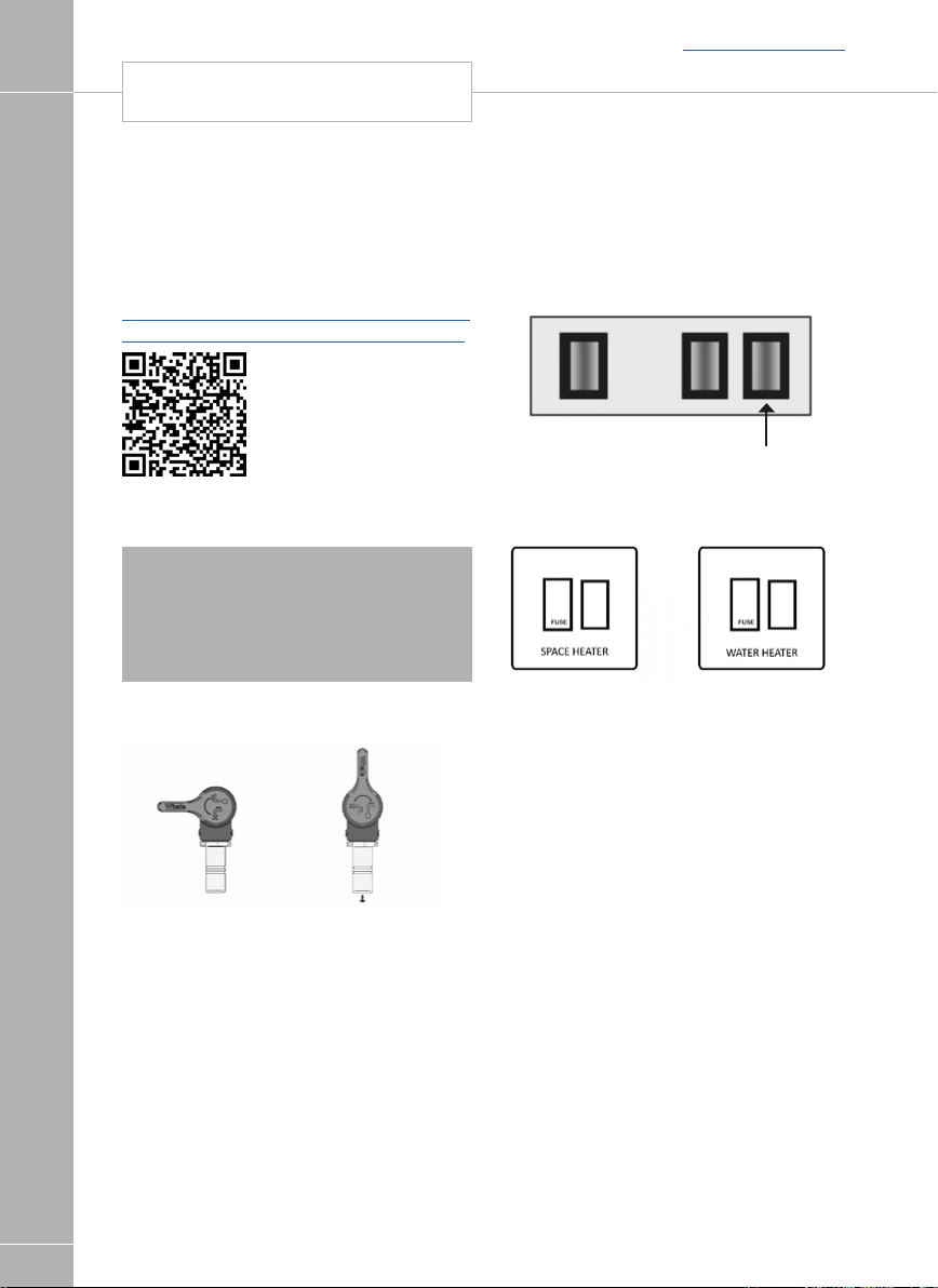
WHALE WATER HEATER
Back to section menu
Whale Water Heater
Your caravan is equipped with a Whale eight
litre gas / electric water heater. Quick reference
and detailed instructions are available for the
water heater, please read these before using
the water heater. They are available at:
http://www.whalepumps.com/rv/resourceslibrary.aspx?Application_listItem_ID=11394
FITTED EQUIPMENT
If you are unable to view the documents on
line, please contact the supplier, your dealer or
Swift for an electronic or paper copy.
Note: Never operate the water heater
without water in it. Please ensure the water
system is primed (water heater drain valve
closed, and water system filled with water),
and that the vehicle is level, before operating
the water heater.
Whale water heater drain valve
Electrical operation of Whale
Water Heater
Once the water system is primed, the 230v
isolation button on the Sargent Power Supply
unit can be switched ON.
Heating
system
In addition, in the base of the wardrobe are
two switched fused spurs which individually
isolate the 230v supply to the Whale space
heating and water heating appliances. These
will be labelled Space Heater and Water
Heater, and once the water system is primed,
the switch marked WATER HEATER must also
be switched ON for electric water heating.
90
Closed Open
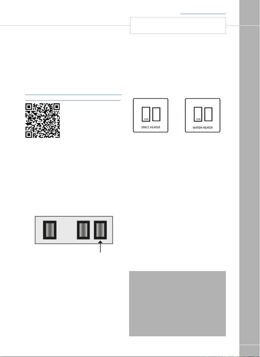
Back to section menu
WHALE SPACE HEATER
FITTED EQUIPMENT
Whale Space Heater
Your caravan is equipped with a Whale
underfloor gas / electric space heater. Quick
reference and detailed instructions are
available for the space heater, please read
these before using the heating system. They
are available at:
http://www.whalepumps.com/rv/resourceslibrary.aspx?Application_listItem_ID=11394
If you are unable to view the documents on
line, please contact the supplier, your dealer or
Swift for an electronic or paper copy.
Electrical Operation of Whale
Space Heater
Before the heating system is used for heating
using electrical (230v) energy, the 230v isolation button on the Sargent Power Supply unit
must be switched ON.
Heating
system
In addition, in the base of the wardrobe are
two switched fused spurs which individually
isolate the 230v supply to the Whale space
heater and water heating appliances. These
will be labelled Space Heater and Water
Heater, and the switch marked Space Heater
must also be switched ON for electric space
heating.
As described in the earlier water heater
instructions, the switched fused spur marked
WATER HEATER must only be switched on if
the water system has been primed, and the
water heater itself is full of water.
Troubleshooting
The Space Heater is equipped with an
electronic diagnostic system which will detect
fault conditions ranging from poor gas or d.c.
supply to internal Space Heater malfunctions.
In the unlikely event of a failure, the red LED on
the Control Panel will light.
In the unlikely event of a failure, the red ‘!’
LED on the Control Panel will light. To identify
the lockout press and hold the Space Heater
Function Button. The temperature control bars
will light to indicate the fault code e.g if 1 bar
lights, the fault code is one, if 2 bars light, the
fault code is 2 etc. Please refer to the table
over page.
Note: To clear a lock out.
If 1, 3, 4 or 5 bars are lit indicating a
lockout - turn the d.c. power ‘off’ and then
‘on’ again at the vehicle’s power supply unit.
If this does not clear the lockout, or any
other lockout is displayed (i.e. 2 or all 12
bars lit) - please press the red Reset Button
on the Water Heater once for one second.
If the problem persists contact:
Whales Support on +44 (0)845 217 2933.
91

REFRIGERATOR
Back to section menu
Warranty
WHALE® is a registered trademark of
Munster Simms Engineering Ltd (also trading
as Whale®).
The Whale® Space Heater is covered by a
3 year warranty. Please complete the
enclosed warranty card and return to Whale.
FITTED EQUIPMENT
For warranty details, please see the enclosed
warranty statement.
Munster Simms Engineering Ltd.
2 Enterprise Road, Bangor
N. Ireland
BT19 7TA
Tel:+44 (0)28 9127 0531
www.whalepumps.com
Email: info@whalepumps.com
Dometic absorption refrigerator
Before you start using the refrigerator,please
read the operating instructions carefully.
These instructions provide you with the
necessary guidance for the proper use of your
refrigerator. Observe in particular the safety
instructions. Observation of the instructions
and handling recommendations is important
for dealing with the refrigerator safely and for
protecting you from injury and the refrigerator
from damage. You must understand what you
have read before you carry out a task.
Keep these instructions in a safe place close
to the refrigerator so they may be referred to
at any time.
Your Basecamp caravan is fitted with a
Dometic RM8406 absorption refrigerator.
Using this model number, please read the
user instructions for the refrigerator, which are
available from the following location:
http://td.dometicgroup.com
92
If you are unable to view the documents on
line, please contact the supplier, your dealer
or Swift for an electronic or paper copy.
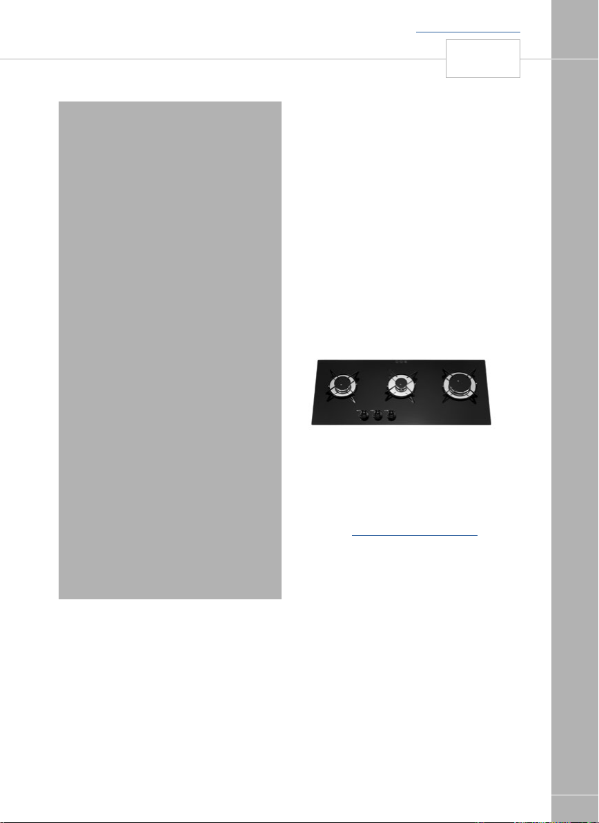
Back to section menu
HOB
FITTED EQUIPMENT
! WARNING:
• Appliances and accessible parts become
hot during use.
• Avoid touching heating elements.
• Children less than 8 years of age shall be
kept away unless continuously supervised.
• This appliance can be used by children
aged from 8 years and above, persons
with reduced physical, sensory or mental
capabilities and/or lack of experience and
knowledge only if they have been given
supervision or instruction concerning
use of the appliance in a safe way and
understand the hazards involved.
• Children shall not play with the appliances.
• Cleaning and user maintenance shall not
be made by children without supervision.
• Unattended cooking on a hob with fat or
oil can be dangerous and may result in
fire.
• Never extinguish a fire with water, switch
off the appliance and cover flame with lid
or fire blanket.
• Danger of Fire: Do not store items on the
cooking surface.
• Do not use harsh abrasive cleaners or
sharp metal scrapers to clean the oven
door glass since they can scratch the
surface, which may result in shattering of
the glass.
• Never use a steam cleaner to clean
appliance.
Our policy is one of continuous development
and improvement. Specifications and
illustrations may change subsequent to
publication.
Provision of ventilation
The use of a gas cooking appliance results in
the production of heat, moisture and
products of combustion in the room in which
it is installed. Ensure that the kitchen is well
ventilated especially when the appliance is in
use: keep natural ventilation holes open.
Prolonged intensive use of the appliance
may call for additional ventilation, for example
opening of a window.
Thetford hob 900 Series
Read the safety instructions and information
on use and maintenance of the hob carefully
before continuing. This will enable you to
use the hob safety and efficiently. Retain this
manual for future reference.
For the latest version of the Thetford Manual,
please visit www.thetford-europe.com.
Symbols
Key symbols:
Introduction
These appliances are designed for cooking
foods, any other use is incorrect and
dangerous. Failure to install the appliances
correctly or improper use, will invalidate any
warranty or liability claims.
This appliances must be installed in
accordance with the local, national and
European regulations in force. Particular
attention shall be given to the requirements
regarding ventilation. Read the instructions
before using the appliances.
WARNING Risk of injury and/or damage
!
CAUTION Hot surface. Risk of injury
ATTENTION Important information
Safety
and/or damage
! This appliance may be used by children
aged 8 years or older and persons with
reduced physical, sensory or mental
capabilities and/or lack of experience and
93

HOB
Back to section menu
knowledge only if they are supervised or
have been given instructions on the safe
use of this application and understand the
potential hazards.
! Keep children younger than 8 years away
from the appliance, except under constant
supervision.
! Do not allow children to play with the
FITTED EQUIPMENT
appliance
! Do not allow children to clean or maintain
this equipment unattended.
! Use only park supplied by the
manufacturer.
! Do not change or adjust anything on the
appliance, unless the change is authorised
by the manufacturer or its representative
! Use the appliance for cooking only and
not for anything else, for example room
heating. This can lead to carbon monoxide
poisoning and overheating.
! The manufacturer cannot be held liable for
damage resulting from improper use or
incorrect setting of controls.
! This appliance is not intended to be
operated by means of an external timer or
separate remote control system.
! The use of the gas cooking appliance
results in the production of the heat in
which it is installed.
! Ensure room has sufficient ventilation when
then appliance is in use. During prolonged
use, additional ventilation may be needed
by opening a window or increasing the
extraction force of the hood.
! Never extinguish a cooking fire with water.
Turn the burner off and cover the flame
with the lid of a fire blanket.
! The burners and pan supports are hot
during and after use. Allow all parts to cool
before touching them, as this can cause
serious injury.
! Unattended cooking on a hob with fat or
oil can be dangerous and may result in fire.
Do not leave the appliance unattended
when in use.
94
! The use of inappropriate hob guards can
cause accidents.
! Do not store items on the cooking surface
of the hob.
! Do not use steam cleaners or pressure
washers to clean the appliance. See
Maintenance and cleaning for instructions.
! Do not allow oil or fat to build up on the
appliance. Clean the appliance after each
use.
1. Gas burners
2. Pan supports
3. Control panel
Before Use
Before using the appliance:
• Ensure that all the packaging materials have
been removed.
• Clean the appliance with warm water and
household detergent and dry carefully with a
soft cloth.
• Ensure that the gas supply is connected and
turned on.
• Ensure that the appliance is connected to
the 12V DC battery for the spark ignition.
• Ensure that the pan supports are positioned
properly.
• Ignite the gas burner and let them burn to
expel odours and vapours first

Back to section menu
HOB
FITTED EQUIPMENT
! ATTENTION: Only use LPG (Liquified
Petroleum Gas). The appliance operates on
propane or butane. Propane is preferred
over butane, because butane provides poor
performance at an ambient temperature
below 10°C and cannot be used at an
ambient temperature below 5°C
Use of the burners
For the exact location of the control knobs,
see main components.
Turning on:
• Push and turn the control knob.
• Turn the control knob anti-clockwise to the
full rate position
-For automatic ignition models: The
automatic ignition sparks and lights.
-For non-ignition models: Hold a lit match or
gas match to the burners.
• Keep the control knob pressed for about 1015 seconds and then release it.
• Adjust the height of the flame.
If the burner accidentally extinguishes turn the
control knob to the 0 position and wait at least
1 minute before re-igniting the burner.
If the burner has not lit within 15 seconds
turn control knob back to the 0 position and
release it. Wait at least 1 minute and repeat
the steps above to turn on the appliance.
Turning Off
• Turn the control knob clockwise to the 0
position to turn off the burner.
Always make sure the control knob is in the 0
position when you have finished using the gas
burner.
Safe cooking
• Do not allow cooking vessels to overlap the
edges of the appliance- use the correct sizes
of pans and position them centrally over the
burners.
Lay-out based on Topline 167
Burner set-up: 1x1, 0kW: 2x1,5kW
• Ensure that there is at least a 10mm gap
between the pans and the edges of the hob.
• Turn the pans so that the handles do not
overhang the front of the appliance.
• Ensure that the flame of the gas burner heats
the bottom of the pan, not the edges.
• Do not leave the appliance unattended when
not in use.
• Do not use the appliance while the vehicle is
moving.
• Turn the control knob back to the 0 position
after cooking.
• Keep the appliance clean and prevent
accumulation of grease and food scraps.
95

HOB
Back to section menu
Maintenance and cleaning
Thetford recommends an annual inspection
service by an approved service centre.
Between annual servicing, clean the appliance
regularly after use. Before any cleaning work is
started, the appliance should be have been left
to cool and be disconnected from the gas and
electrical supplies.
FITTED EQUIPMENT
• Always remove any spills or contamination
immediately after use with soap and hot
water. Towel dry the surface with a soft cloth.
• Use a non-abrasive multi-purpose cream
cleaner and a nylon scourer pad to clean
more stubborn dirt or grease.
• For routine cleaning of the glass surface, use
a cleaning cream and clean cloth or paper
towel. After cleaning, wipe dry with a dry
paper towel.
! WARNING: Do not use abrasive
cleaners, metal scouring pads or hard
brushes. They could damage the appliance.
! WARNING: If you clean the burner rings,
ensure that the holes are not clogged.
Note: The control knobs can be removed
for cleaning. The knobs are easy to replace.
Gas leaks
As soon as you smell gas:
• Ensure that all burners are turned off.
• Extinguish all naked lights and do not
smoke.
• Shut off the gas supply at the gas bottle
immediately.
• Do not use electrical switches.
• Open all doors and windows.
! WARNING: LPG is heavier than air.
Escaping gas accumulates at lower levels.
By following the strong, unpleasant smell of
gas, you can determine where the leak is
located. To investigate where it is exactly,
use a special leak detection spray. Never
use an open flame to find the leak!.
96

HOB TROUBLESHOOTING
Trouble shooting
Problem Problem cause Solution
Burners do not burn or
burn unevenly
Automatic ignition does
not spark
Control knobs do not function Knobs are mounted
If you cannot solve a problem, contact
the authorised local Services Centre or
Thetford Customer Service in your country.
Gas bottle is empty
Gas tap is closed
Burner caps are not correctly
positioned
Burners are wet or clogged
12V DC battery is discharged
Connections are loose
Ignition points is wet or dirty
incorrectly
Fill bottle
Open tap
Allow caps to cool, then
reposition them
Dry or clean burners
Charge battery
Secure connections
Dry or clean ignition point
Install knobs correctly
Servicing
All servicing must be carried out by an
approved competent person. Before any
service work is started, the appliance should
have been left to cool and be disconnected
from both gas and electrical supplies. After
each service the appliance must be checked
for gas soundness and electrical safety.
For service, please contact your authorised
local Service Centre giving details of the model
and serial number on the data badge plus date
of purchase.
Back to section menu
FITTED EQUIPMENT
Putting in storage
• Close the gas valve at the gas bottle.
• Disconnect the battery.
• Ensure that the control knobs are in the 0
position.
• Wipe the appliance clean and dry.
97

HOB TECHNICAL SPECIFICATION
Technical Specifications
FITTED EQUIPMENT
Back to section menu
98
This application is suitable for use with LPG
(liquefied Petroleum Gas) and should not be
used with any other gas.
! WARNING: This application must be
earthed
Disposal
Your product has been designed and
manufactured with high quality materials and
components, which can be recycled and
reused. When your product has reached the
end of life, dispose of the product according to
the local rules. Do not dispose of the product
with the normal household waste. The correct
disposal of your old product will help prevent
potential negative consequences to the
environment an human health.

Questions
If you have questions about your product,
parts, accessories or authorised services:
• Visit www.thetford-europe.com
• If you cannot solve a problem, contact the
authorised local Service Centre or Thetford
Customer Service in your country.
Warranty
Thetford BV offers the end users of its
products a three-year-warranty. In case
of malfunction within the warranty period,
Thetford will replace or repair the product.
In this situation, the costs of replacement,
labour costs for the replacement of defective
components and/or the costs of the parts
themselves will be paid for by Thetford.
Purchased space parts carry a one-yearwarranty. Any fitting and/or labour costs are
not covered by warranty.
1. To submit a claim under this warranty, the
user must take the product to an authored
Thetford Service Partner. The claim will be
assessed there.
2. Components replaced during repair under
warranty become the property of Thetford.
3. This warranty does not prejudice current
consumer protection laws.
4. This warranty is not valid in the case of
products that are used for commercial
purposes.
5. Warranty claims falling into one of the
following categories will not be honoured:
• The product has been improperly used
or the instructions in the manual have not
been followed
• The product has not been installed in
accordance with the instructions
• Modifications have been made to the
product
• The product has been repaired but not by
an authorised Thetford Service Partner
• The serial number or product code has
been tampered with or removed
• The product has been damaged by
misuse
Back to section menu
HOB
FITTED EQUIPMENT
99
 Loading...