

Page 1

Bare case parts nomenclature
NO PARTS PS
1 BEZEL, FRONT 1
2 BEZEL, FRONT, SUB 1
3 BUTTON, POWER 1
4 BUTTON, RESET 1
5 LENS 1
6 COVER, 5.25 FDD 4
7 COVER, 3.5 FDD 2
8 SPRING 1
9 PLATE, CAGE, 5.25 2
10 SPEAKER 1
11 BULKHEAD ASSY 1
12 SHIELD, I/O 1
13 CAGE, 3.5 ASSY 1
14 CARDGUIDE 1
15 POWER SUPPLY 1
16 BRACKET, P/S 1
17 COVER, TOP 1
18 CHASSIS, BOTTOM 1
uiet Power
Q
FS20-H20 series
Liquid cooled case
Installation guide
NO PARTS PS
19 PANEL, FRONT 1
20 PANEL, REAR 1
21 SIDE, PANEL 2
22 CAGE, 5.25 1
23 FILLER TOP 3.5 1
24 BRACKET, HDD 1
25 SLIDE BRACKET P/S 1
26 BASE, M/B 1
27 CROSS BAR 1
28 BRACKET, LED ASSY 1
29 FAN 120MM 1
30 SNAP RIVET 8
31 SHIELD 1
32 THUMB SCREW 2
33 SCREW 1
34 RIVET, ALUMINUM 49
35 RIVET-SUS 8
36 SCREW 20
MEMORY BOARD CROSS
37
BAR
1
Swiftech Inc., 1703 E. 28th St., Signal Hill, CA 90755 T. (562) 595-8009 F. (562) 595-8769 - 1 -
Page 2

Swiftech Inc., 1703 E. 28th St., Signal Hill, CA 90755 T. (562) 595-8009 F. (562) 595-8769 - 2 -
Page 3

BEFORE YOU BEGIN!
Components inst allation
1. Open the side-panel #21 by loos ening thumb screws #32
2. Remove the main cross bar #27.
3. A special memory board cross bar (#37) specific to server applications is provided with the lose parts. It is not shown in the schematic above,
and can be safely discarded in most consumer applications.
4. Loosen screw #33, and remove the front bezel #1
5. Remove the top cover #17
You now have full access inside the case to proceed with the installation of your power-supply, motherboard, hard drive (s) and various components.
Liquid cooling circuit notes
• The wat er-block is installed onto the back-panel for safe shipping. Unscrew the 4 springs ass emblies, and remove the four standoffs used to
secure the block onto t he back-panel. You will need these standoffs later, together with the spring and screw assemblies to install the water-
block to your motherboard.
• During installation of your motherboard inside the case, it is good practic e to strap the block out of the way, using a rubber band for example.
• Your cooling circuit is already filled with coolant (90% pure water, 10% coolant). All you need to do is to install the water-block to your CPU.
Water-block pre-installation notes:
Intel
The MCW 462 water-block is shipped with Intel
Intel’s various mounting form f actors. Please refer to the Intel
motherboard.
AMD
Please remove the Intel
below.
Please f ollow the separate installation guides for AMD or INTEL p roces sors.
• Power to the pump: a spare power cord is provided t o supply A/C power to the pump. It needs to be connected to an A/C outlet.
®
processors
®
pr ocess ors
®
Pentium® 4 brackets pre-installed. These brackets feature different mounting holes to accommodate
®
Pentium® 4 brackets from the MCW462 water-block, using the provided socket wrench, then follow the AMD® installation guide
®
installation guide below, to identify the holes that will be needed for your particular
Parts list
Parts AMD INTEL QTY PARTS AMD INTEL QTY
Water-block Common to both 1 6-32 lock-nuts Common to both 4
6-32 x 1 ½” screws (f or HS) Common to both 4 Black fiber washers X 8
Standoff s Common to both 4 Thermal grease Common to both 1
Springs Common to both 4 Tube insert Common to both 2
Nylon flat washers X 8 P4 brackets X 2
Nylon shoulder washers X 4 4-40 socket screws X 4
Swiftech Inc., 1703 E. 28th St., Signal Hill, CA 90755 T. (562) 595-8009 F. (562) 595-8769 - 3 -
Page 4

• Install standoffs in M B
• Install the MB inside the case.
II. Water-block installation
• The case should be laying flat on a table.
• Insert the processor into the s ocket, and lightly coat the processor core with the
included thermal compound (Arctic Alumina). Only a paper-thin coat is
necessary. It should be applied using pref erably a razor blade, or a credit card,
held between thumb and index at a 45-degree angle. It is critical to ascertain that
the entire core is covered with a unif orm coat of thermal compound. Thermal
performance will dramatically decrease if any portion of the core is not covered by
thermal c ompound.
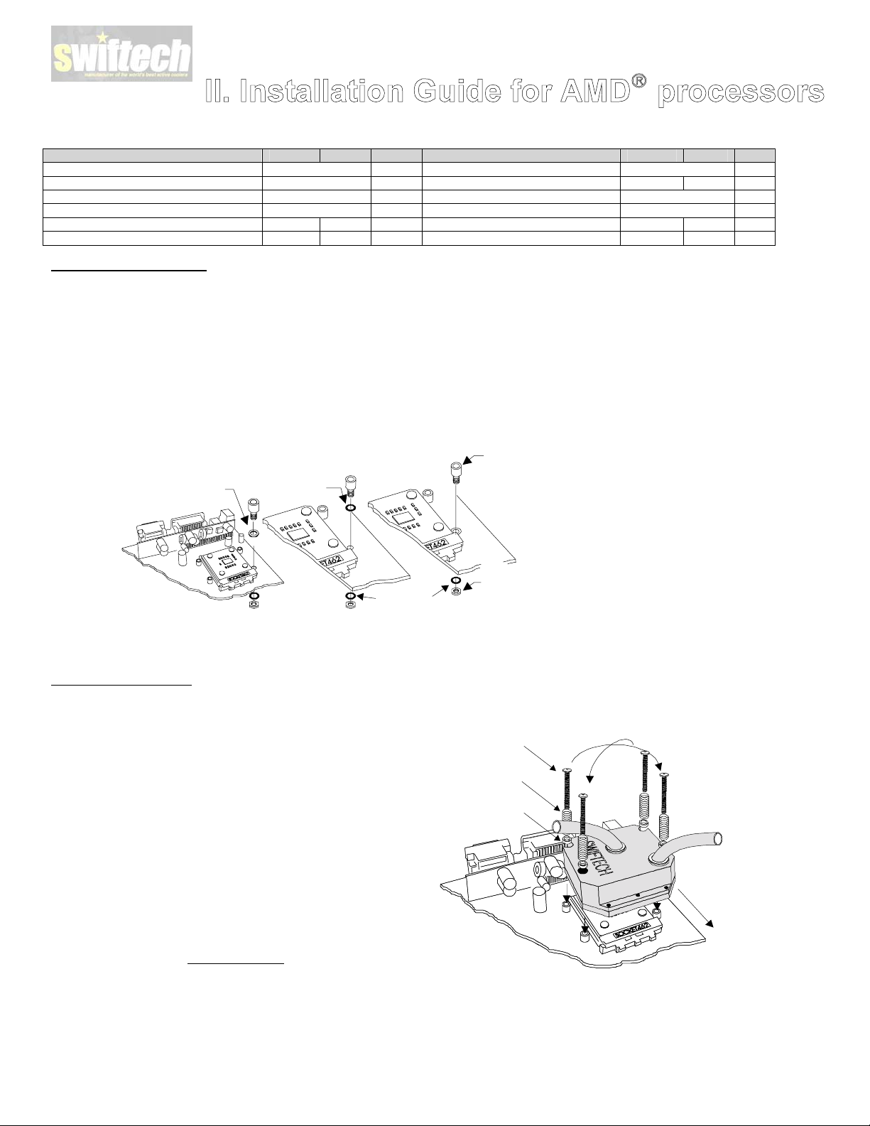
I. Prepar ing the motherboard
Fiber washer
Standoff
Lock-nut
to back side of
the MB
Remove the stock heatsink support base (the black
plastic frame that clips down to your motherboard).
This will reveal the four mounting holes we use to
install our standoffs. Install a standoff in each one of
the holes. Keep the standoff centered over the MB
holes, and secure with fiber washers and locknuts on
backside of the MB.
• Prepare 4 assemblies composed of a 1 ½” screw,
and 1 spring.
• Identify the mounting holes on the bracket for
your processor, as shown in the schematic
below
Crisscros
tightening
pattern
2"
1 1/2“ screw
2"
Spr ing
2"
2"
• Install the MCW462-U on the CPU.
• Gradually tighten the screws in a crisscross pattern until you feel that they reach the bott om of the standoff. A “finger-tight” lock is sufficient.
Adjustments such as tightening the screws only partially are strictly prohibited
core and the heat sink, and result in CPU overheating.
. Such attempts will result in improper cont act between the CPU
Swiftech Inc., 1703 E. 28th St., Signal Hill, CA 90755 T. (562) 595-8009 F. (562) 595-8769 - 4 -
Page 5
Parts list
Parts AMD INTEL QTY PARTS AMD INTEL QTY
Water-block Common to both 1 6-32 Lock-nuts Common to both 4
6-32 x 1 ½” screws (f or HS) Common to both 4 Black fiber washers X 8
Standoff s Common to both 4 Thermal grease Common to both 1
Springs Common to both 4 Tube insert Common to both 2
.230x.096 Nylon spacers X 8 P4 brackets X 2
.220x.046 Nylon spacers X 4 4-40 s ocket screws X 4
I. Prepar ing the motherboard
• Install standoffs in M B
Determine which standoff washers to use, depending on your MB mounting holes:
o Large holes .230”(5.8mm) diameter : use .220x.046 Nylon spacers. The washers fit inside the MB hole.
o Small grounded holes .150”(3.8mm) diameter: you c an recognize gr ounding by a silver ring around the holes; no washers needed nor
necessary.
o Small holes, NOT grounded (bare circuit board): you must use black fiber washers, or damage to the MB may occur.
MB with
large holes
Use .220x.046
nylon spacer
(fit inside the hole)
Install standoff in each one of the four holes
surrounding the socket. Keep the standoff &
washer centered over the MB holes, and secure
with a fiber washer and lock-nut on backside of
the MB.
MB with
small holes,
NOT grounded
Use black
MB with
small holes,
grounded
No washer
necessary
Standoff
Fiber washer
Fiber washer
• Re-install the MB inside the case.
II. Water-block installation
• The case should be laying flat on a table.
• Insert the processor into the s ocket, and lightly coat the
• Prepare 4 assemblies composed of a 1 ½” screw, 1 nylon
• Install the MCW462-U block on the CPU. The copper base of
• Gradually tighten the screws in a crisscross pattern until you
process or core with the included high quality thermal
compound (Arctic Alumina). Only a paper-thin coat is
necessary. It should be applied using pref erably a razor blade,
or a credit card, held between thumb and index at a 45-degree
angle. It is critical to ascertain that the entire core is covered
with a uniform coat of thermal compound.
spacer, and 1 spring as shown in Figure 2. Drop each
assembly into the MCW 462-U mounting holes.
the MCW 462-U f eatures a large step f or clearance with the
socket cam box. Make sure to respect this orientation. Keep
the heat sink mounting holes lined up with the standoffs. Avoid
twisting the block to pr event smearing the thermal compound.
feel that they reach the bottom of the standoff. A “finger-tight”
lock is sufficient. Adjustments such as tightening the screws
only partially are strictly prohibited
in improper contact bet ween the CPU c ore and the heat sink,
and result in CPU overheating.
. Such attempts will result
Fiber washer
Lock-nut
on back side of
the MB
1 1/2“ Philips
screw
Spring
.230x.096
Nylon spacer
Crisscros
tightening
pattern
Large step side
over cam box
Swiftech Inc., 1703 E. 28th St., Signal Hill, CA 90755 T. (562) 595-8009 F. (562) 595-8769 - 5 -
Page 6

II. Temperature troubleshooting
IMPORTANT WARNING: AMD compatible motherboards measure the CPU t emperature via a ther mal probe located inside the socket. The probe only
measures the air temperature underneath the CPU. Motherboard manuf acturers use mathematic formulas to extrapolate the actual CPU temperature.
Such formulas use corr ection f actors to account for airflow around the socket generated by a conventional heatsink f an cooler. In a liquid cooling
environment, there is no airflow at all around the socket, since there is no fan attached to the water-block. This leads to erroneous readings from the
motherboard thermal probe, which reports much higher CPU temperatur es than actual. Troubleshooting help is available on our web site at
http://www.swiftnets.com
in the Servic e & Support section, Troubleshooting sub-section.
Parts list
Parts QTY PARTS QTY
MCW40™ assembly 1 3/8” vinyl tubing 3’
2-56 S/S socket screw 4 Tube insert 4
Nylon screw spacer 4 Thermal compound 1
Nylon washer 4 Socket wrench 1
Spring 4
Installation diagram
Tube insert
Nylon washer
Spring
Nylon screw spacer
2-56 S/S socket screw
1. Preparing your graphics card
a. Remove the existing heat sink
b. Carefully clean the GPU (graphics processing unit)
c. Lightly coat the GPU with the pr ovided thermal compound. Only a paper-thin coat is necessary. It should be applied using
preferably a razor blade, or a credit card, held between thumb and index at a 45-degree angle.
2. Installing the MCW40™ GPU Cooler
a. The MCW 40™ retention mechanism uses the four mounting holes standard specified in GeForce™ GPU 's as shown in the
schematic above. It c an also be installed with other graphics processors by using permanent bonding agents, such as thermally
conductive epoxies. W e recommend Arctic Silver™ or Arctic Alumina™ epoxy.
b. The MCW 40™ can be oriented in any position, as needed to clear components on the board, except for one: the inlet and outlet
should not be oriented towards the motherboard as the block would otherwis e interfere with installation of the graphics card.
Swiftech Inc., 1703 E. 28th St., Signal Hill, CA 90755 T. (562) 595-8009 F. (562) 595-8769 - 6 -
Page 7

or replac e the heat sinks with low profile aft er-market parts. To re-install these heat sinks, Arctic Alumina™ epoxy is
recommended f or optimum performanc e inst ead of thermally conductive tape.
d. Note concerning removal of the tubing: Push in collet squarely against f ace of fitting. With the collet held in this position, the
tube can be removed wit h a firm pull. D o not attempt to pull the tube out without pushing s quarely against the c ollet. This may
result in damaging the fitting. Further details for using quick-connect fittings are als o available here:
http://www.johnguest.com/install_6.shtm#disconnect
c. If the graphics card comes equipped with memory heat sinks, it may become necess ary to remove
e. Re-install the gr aphics card in the AGP slot, and proceed with filling and bleeding the cooling circuit. A mix of 75% purified water
and 25% antifreeze is recommended
3. Final inspection
Once the installation is completed, it is always a good idea to test the circuit for leaks, prior to powering up the computer.
Troubleshooting help is available on our web site at www.swiftnets.com
The Quiet Power Case is equipped with an inline centrifugal pump operating on AC. In order to allow the pump to operate concurrently with the rest of the
computer, the pump is connected to a relay s witch as shown here:
, or by calling customer support at 562-595-8009.
The relay switch MUST be connected to one of the power supply 4-pin
connectors, AND the socket needs to be connected to an A/C source
with the provided cord. OTHERWISE YOUR PUMP WILL NOT WORK !
Swiftech Inc., 1703 E. 28th St., Signal Hill, CA 90755 T. (562) 595-8009 F. (562) 595-8769 - 7 -
Page 8

Pump Relay switch operations
For normal operations, the L wire from the A/C socket is
connect ed to the N/O (normally open) position of the switch. This
means that when the computer is off, there is no current from the
power supply to the switch, and the relay is opened, disallowing
A/C to the pump. Conversely, as soon as you turn the computer
on, the switch becomes energized by the power supply, and the
relay closes, allowing A/C current to pass to the pump.
For maintenance operations, if you want to turn the pump on
without operating the rest of the computer, you may temporarily
connect the L wire to the N\C (normally closed) position. T his is
particularly us eful for filling and bleeding the circuit, as you
wouldn’t want the computer running while the cooling circuit is
not completely operational. WARNING: do not forget to
reconnect to N\O once you are ready to run the computer: if
you leave the L wire connected to N\C, the pump will shut
off as soon as the relay is energized by the power supply.
Relay switch connection diagram
E
N
N\O N\C
_
+
A/C
Socket
L
Pump’s
Switch
CB
From Power Supply
From Pump
+12v
Ground
Black
White
Green
Swiftech Inc., 1703 E. 28th St., Signal Hill, CA 90755 T. (562) 595-8009 F. (562) 595-8769 - 8 -
Page 9

How to use quick connect fittings
Cut tube square
Disconnecting a fitting
Ensure s ystem is depressuris ed before removing fitting.
Cut the tube square. It is ess ential that the outside
diameter be free of score marks and that burrs and sharp
edges be removed before inserting into fitting. For soft or
thin walled plastic tubing we recommend the use of a
tube insert.
Insert tube
Fitting grips before it s eals. Ensure tube is pushed in to the
tube stop.
Push up to tube stop
Push the tube into the fitting, to the tube stop. The collet
(gripper) has st ainless steel teeth which hold the tube
firmly in position while the 'O' ring provides a permanent
leak proof seal.
Pull to check secure
Push in c ollet squarely against face of fitting.
With the collet held in this position, the pipe can be removed. The fitting c an then be re-used.
Your kit also c ontains a releas e aid tool which you can place over the
collet, and helps pushing the collet squarely while removing the tube:
General guidelines with regards to tube bending:
In general, you should avoid sharp bends. A sharp bend may
result in kinking the tube, and restrict or c ompletely prevent the
flow.
Once all the elements are in place, you can install your
motherboard inside the case and proc eed, with the water block
installation.
Pull on the tube to check it is secure. It is good practice to
test the system prior to leaving site and/or before use.
Swiftech Inc., 1703 E. 28th St., Signal Hill, CA 90755 T. (562) 595-8009 F. (562) 595-8769 - 9 -
Page 10

Filling & bleeding the circuit
We recommend using the following mix: 90% purified
water, and 10% of one of the following pr oducts:
Swiftech’s specially f ormulated HydrX coolant, or
RedLine water wetter,
or Zerex Racing Coolant.
In order to fill and bleed the circuit, you will need to activate
the pump. Sinc e you do not want to run the c omputer until the
cooling circuit is completely operational, you should
temporarily connect the L wir e to the N\C position of the
switch. WARNING: do not forget to reconnect to N\O once
you are ready to run the computer: if you leave the L wire
connected to N\C, the pump will shut off as soon as the
relay is energized by the power supply, and there would
be no flow in the cooling circuit, causing your CPU to
overheat.
1. Place a holding tank containing your cooling fluid
above the computer.
2. Connect the ¼” tube provided with your kit. Tube 1
goes to valve 1 and tube 2 goes to valve 3
3. Plunge tube 1 only into the holding tank, making sure
it is entirely submerged
4. Open valve1, close valve 2, open valve 3
5. Prime the circuit by gently sucking in air from tube 2,
just enough that you see the liquid starting to flow
down in tube 1
6. Now, you can plunge tube 2 back into the holding
tank
7. Start the pump
8. Let the pump run for 1 minute as shown in the picture
to the right. The liquid should be flowing freely from
tube 2 into the holding tank.
9. Important step: after a minute, and while the
pump is still running:
• Take the holding tank and tubes into one hand –
making sure that the tubes remain plunged int o
the liquid,
• Then lay the c omputer down f or just a few s econds
once flat on it’s back, and once flat on its belly. This
will bleed any air still trapped int o the circuit.
Swiftech Inc., 1703 E. 28th St., Signal Hill, CA 90755 T. (562) 595-8009 F. (562) 595-8769 - 10 -
Page 11

1. Open valve 2 for a couple of s econds, to allow
a
e
air trapped into the valve to escape. Close valv
again.
2. Now, close val ves 3 and 1, and open valve 2.
The system is now full, bled, and ready to use,
as shown in the picture to the right.
3. Turn off the pump by disconnecting it from
A/C.
4. With both tubes still inside valves 1 and 3,
carefully place the holding tank below the
computer (on the floor for example)
5. Disconnect the tubes f rom valves 1 and 3.
Whatever little liquid was still trapped in the
tubes will flow back into the holding tank
without making a mess :-)
6. FINALLY, REMEMBER to reconnect the L
wire from the s ocket to the N\O position on the
switch !
- Intentionally left blank -
Swiftech Inc., 1703 E. 28th St., Signal Hill, CA 90755 T. (562) 595-8009 F. (562) 595-8769 - 11 -
Page 12

In summary
Swiftech Inc., 1703 E. 28th St., Signal Hill, CA 90755 T. (562) 595-8009 F. (562) 595-8769 - 12 -
 Loading...