

Page 1

Copyright Swiftech 2006 - Subject to change without notice - While all efforts have been made to provide the most comprehensive tutorial possible, Swiftech assumes no liability expressed or implied for any damage(s) occurring to your components as a result of using Swiftech cooling products, either due to mistake or omission on our part in the above instructions, or
due to failure or defect in the Swiftech™ cooling products. In addition, Swiftech assumes no liability, expressed or implied, for the use of this product, and more specifically for any, and all damages caused by the use of this product to any other device in a personal computer, whether due to product failure, leak, electrical short, and or electro-magnetic emissions.
Next, estimate the most direct route for the
tubing to the Apogee water-block, leave sufficient tube length to make a nice and wide radius,
cut any excess and connect the tubes to the
Apogee barbs (in no particular order).
Tighten each tube to the barbs with the provided
hose clamps. Make sure the clamps close to the
last click.
You are now ready to move to the next step: fillingup the system.
For safety reasons, do not connect the
power-supply to an electrical outlet, and
do not connect the motherboard to the power-supply at this point.
Swiftech assumes no liability expressed or implied
for any injury or death occuring as a result of electrical shocks, including as a direct or indirect result
of defects in Swiftech components.
Mix the 2oz bottle of HydrX included with your
accessories to 1/2 a liter of distilled water (do not
use tap or mineral water), and proceed with the next
steps.
We suggest that you install the Apogee
water-block to the motherboard before you
install the motherboard into the case. This will be
more convenient to cut the appropriate length of
tubing.
Please follow the Apogee inst allation guide included
in the box for how to setup your water-block with different microprocessors.
Once done, proceed with the installation of the
motherboard into the case as shown in the following
steps.
Lay the case flat on its back, and engage the motherboard with the rear connectors side first as shown
above.
Gently push the tubing aside to free a passage for
the motherboard.
The motherboard is now ready to be fastened to the
chassis.
Unfasten screws from both side-panels, and set
panels aside
This is the system as shipped
Unfasten and remove both hard drive cages: your
accessories are inside
Unfasten and remove the power supply frame: your
water-block is inside
You are now ready to populate the Quiet
Power case with your components just as
you would any other case.
We do recommend installing the power supply first.
Standard ATX PSU’s will fit without issues. Modular
units are 1 inch longer than normal, and require
relocation of the pump and the lowermost 120mm
fan and duct assembly. A second set of holes is
available to relocate the pum
p.
Please go to steps A thru E if you
are using a modular PSU.
1
2
3
4
5
6
7 8 9
11
10
Loosen the two screws holding the reservoir to the
chassis by a few turns.
Start pouring the coolant until the reservoir is full.
Loosen and set aside the reservoir fill-cap.
Gently pull the reservoir outwards.
12
13
14 15
SWIFTECHTMQUIET POWER P180 INSTALLATION GUIDE
Toll Free Tech Support Hot Line: (888)-857-9438
(Mo-Sat 8am-8pm Pacific Standard Time)
Page 2
Copyright Swiftech 2006 - While all efforts have been made to provide the most comprehensive tutorial possible, Swiftech assumes no liability expressed or implied for any damage(s) occurring to your components as a result of using Swiftech cooling products, either due to mistake or omission on our part in the above instructions, or due to failure or defect in the Swiftech™
cooling products. In addition, Swiftech assumes no liability, expressed or implied, for the use of this product, and more specifically for any, and all damages caused by the use of this product to any other device in a personal computer, whether due to product failure, leak, electrical short, and or electro-magnetic emissions.
Snap out the fan & duct assembly.
Unfasten the 4 screws holding the fan to the fan
duct, and discard the duct as it will no longer be
needed.
Unfasten the 2 nuts holding the pump to the case
floor, lif t the pump from its post s, and set the pump
out of the way.
Unfasten the two posts, and relocate them as
shown to the right.
Power-on the power supply, keeping your
finger on the button. The pump will start after 1
second delay and immediately syphon-off all the
fluid from the reservoir. Promptly power-off the
power supply to prevent damage to the pump:
W
W
arning!
arning! the pump cannot run “dry” for more than
a few seconds or this will damage its bearing permanently and void your warranty. Now refill the
reservoir, and repeat this procedure: normally only
one more time is needed until the reservoir is at
about half-level and the pump can run without
interruptions.
While the pump is running at first, the fluid will be
full of micro-bubbles, and appear milky and foamy
as shown below. Simply allow the pump to run
10~15 minutes for all the bubbles and foam to
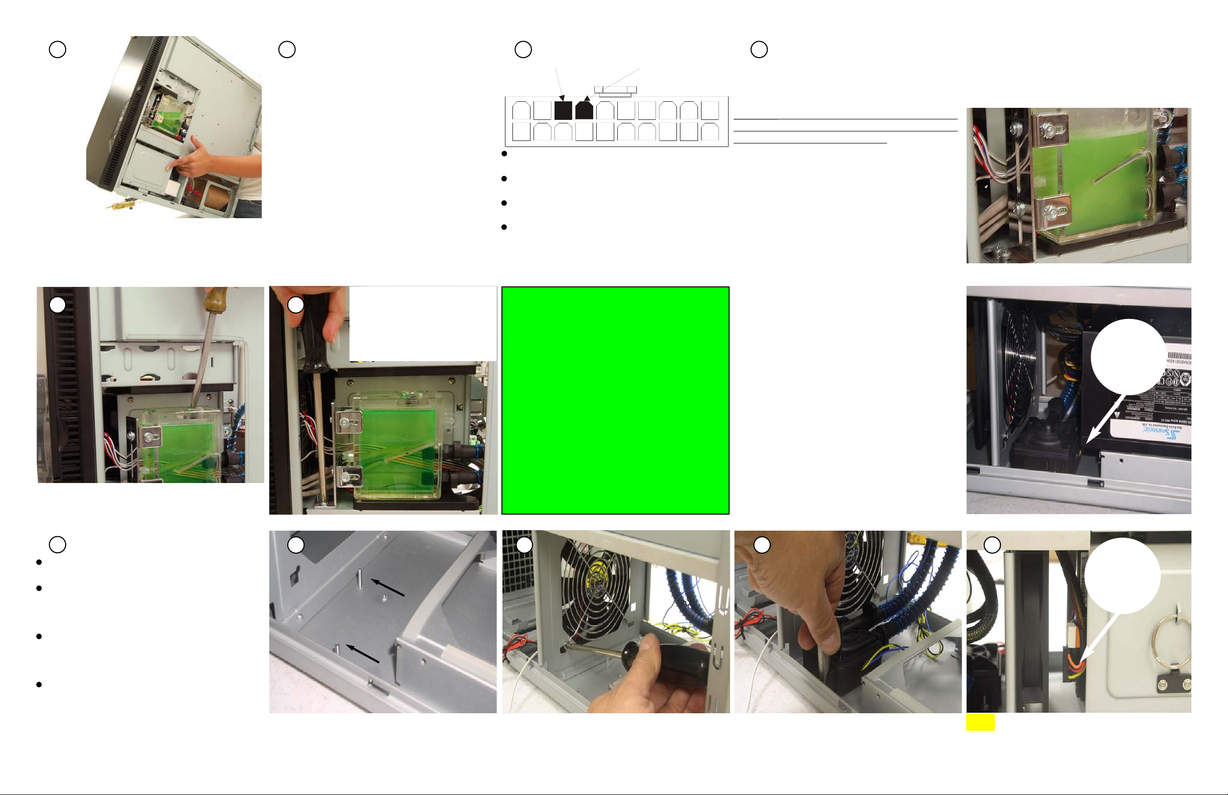
At this point, you need to be able to startup the pump in order to complete the fill-up procedure.
For safety reasons, you must be able to power
on the PSU without connecting it to the motherboard. The Internet contains numerous references
on how to use a paper-clip to short-out pins 14
(PS-ON, green wire) and 13 (GND, black) of the 20
pin ATX connector (shown to the right) but we recommend instead using a power-supply tester.
These common devices are widely available on the
Internet (Google key word: "PSU tester"), and
among Swiftech resellers.
Use “elbow” power and SATA connectors
for your hard drives.
16 17
19
18
20 21
A
B C D
Tilt the case backwards: this will allow more fluid to
fill-up the system, then top-off the reservoir again.
clear up.
Place the fill-cap back, and gently tighten it, preferably with a wide tip screw driver.
Push the reservoir as far back as
possible, and tighten both
screws; finally connect the LED
Molex connector to the power
supply.
This completes the installation of
your Swiftech liquid cooling system. Please allow your system to
run for a few hours and inspect it
for leaks before you complete the
electrical connections to mother-
board and other components.
~
Please refer to Antec’s installa-
tion guide for the chassis electri-
cal connections.
Now, connect the pump 4-pin molex connector to
the power supply.
Inspect the bench area to make sure that there is
no moisture anywhere.
Verify that the power button of the power supply
is off .
Finally Connect the power supply to an A/C out-
let.
MODULAR POWER SUPPLIES
STEPS A THRU E
The following steps are only required when a modular power supply is used.
In effect, Modular Power Supplies are longer than
standard. The pump and the lowermost 120mm fan
and duct assembly need to be relocated - as shown
to the right, in order to allow the additional clearance needed for the power suppply and cables.
Relocate the pump mounting posts as shown
above.
Re-install the fan as shown, the fan label should be
facing the power supply.
Fasten the pump back to its new location. A 5/16
“deep” socket is ideal to tighten these nuts. “Finger
tight” is only needed.
E
Longer than
standard
Elbow
Connectors
TIP:
13
14
(GND) BLACK
(PS-ON) GREEN
 Loading...