

Page 1
Packing list
Parts Qty Parts Qty
Heat Sink 1 Springs 4
Fan 1 Nylon flat washers 8
Fan guard 1 Nylon 6-32 Hex nuts 4
6-32 x 2” screws (for fan) 4 Black fiber washers 4
6-32 x 1 ½” screws (for HS) 4 Thermal grease 1
Standoffs 4 4-40 socket screws 4
I. Preparing the motherboard
1. You must uninstall your MB prior to installing the MCX478 heat sink.
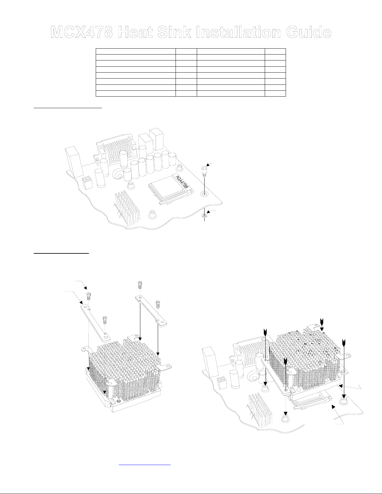
2. Install standoffs in MB.
Mounting Brackets 2
3. Re-install the MB inside the case.
II. Heat sink Installation
1. Install the two mounting brackets onto the heat
4-40 x 1/4“
socket screw
sink, using the provided 4-40 x 1/4” socket screws:
Bracket
Install standoff in each one of the four
holes surrounding the socket. Keep the
standoff centered over the MB holes, and
secure with nylon hex nuts on backside
of the MB. If you are going to
Standoff
Nylon, hex nut
on back side of
the MB
assemble/disassemble the heat sink
frequently, we recommend finishing the
installation by putting a drop of “Crazy
Glue “ at the junction between standoff &
MB, and between nylon hex nut & MB.
This will lock the standoff onto the MB,
and further prevent it from spinning lose
during frequent assembly and
disassembly operations.
3. Insert the processor into the socket, and lightly coat the processor core
with high quality thermal compound. Only a paper thin coat is
necessary. It should be applied using preferably a razor blade, or a credit
card, held between thumb and index at a 45 degree angle. It is critical to
ascertain that the entire core is covered with a uniform coat of thermal
compound. Thermal performance will dramatically decrease if any portion
of the core is not covered by thermal compound. We recommend Arctic
Silver or similar high end compound for superior thermal conductivity.
4. Place the bare MCX478 heat sink over the CPU as shown in the picture
below. The step side should be located over the socket’s cam box. Keep
the heat sink mounting holes lined up with the standoffs.
2. For the next step, the case should be laying flat on
a table
Copyright Swiftech 2001 – All rights reserved – Last revision date: Oct. 2001
Rouchon Industries, Inc., dba Swiftech – 1703 E. 28
E Mail: Swiftech @swiftnets.com – URL: http://www.swiftnets.com
th
Street, Signal Hill, CA 90806 – Tel. 562-595-8009 – Fax 562-595-8769
Socket
cam box
Page 1
Information subject to change without notice
Step
side
Page 2
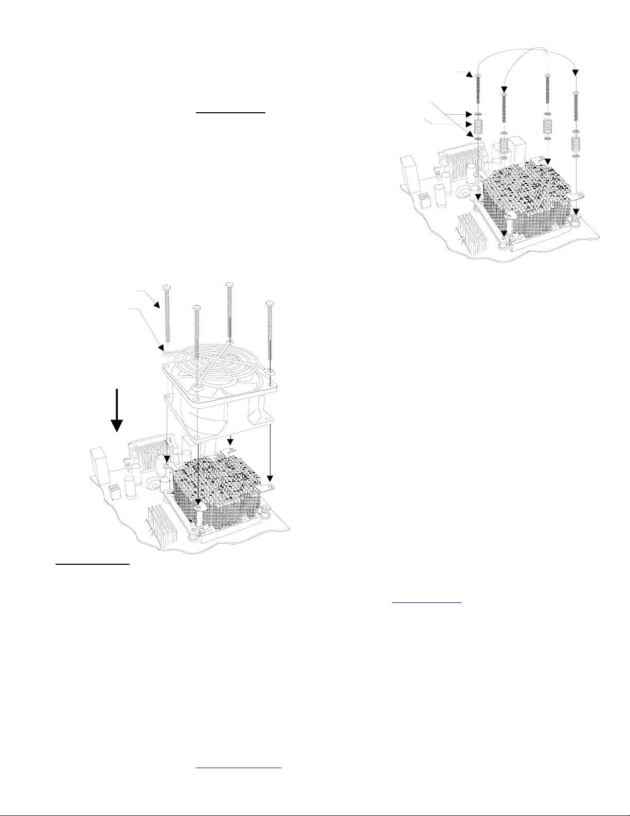
5. Prepare 4 assemblies composed of a 1 ½” screw, 2 nylon flat
washers, and 1 spring as shown in the picture to the right. Drop each
assembly in the bracket mounting holes. While gently pressing at the
center of the heat sink, start tightening the screws gradually in a
crisscross pattern until you feel that they reach the bottom of the
standoff. A “finger-tight” lock is sufficient. Over tightening may result in
stripping the nylon hex nut. Conversely, adjustments such as tightening
the screws only partially are strictly prohibited
result in improper contact between the CPU core and the heat sink, and
result in CPU overheating.
. Such attempts will
Criscross tightening pattern
6-32 x 1 ½“
Philips screw
Nylon flat
washers
Spring
6-32 x 2“
Philips screw
Fan guard
Direction of
the flow
(fan label
facing down)
III. Final inspection
Now that the heat sink is installed, startup your computer, go into the BIOS and observe the CPU temperature. Under normal ambient
temperature conditions, the processor temperature should never exceed 55° C (130 ° F). If it does, shut down the computer immediately,
and review your entire installation. Troubleshooting help is available on our web site at www.swiftnets.com
support at 562-595-8009.
DISCLAIMER: Swiftech assumes no liability whatsoever, expressed or implied, for the use of these products.
6. Fan Installation: Place the fan over the heat sink. The airflow should
be blowing down (fan label facing down). Place the fan guard over the
fan. Tighten the four 6-32 x 2” screws. The fan is equipped with two
connectors: a four pin molex connector which must be connected to the
power supply, and a 3 pin single wire connector which connects to the
MB fan sensor header.
7. Optional fan rheostat: a rheostat model # RH070 is sold separately,
and allows to adjust the fan speed. It connects between the fan power
connector and the power supply connector. Please consult your
distributor if you wish to purchase this item. Reducing the fan speed
reduces fan noise up to 9 dBA. It also reduces thermal performance,
and will affect overclocking performance accordingly. It is however
perfectly appropriate for non overclocked processors.
, or by calling customer
Copyright Swiftech 2001 – All rights reserved – Last revision date: Oct. 2001
Rouchon Industries, Inc., dba Swiftech – 1703 E. 28
E Mail: Swiftech @swiftnets.com – URL: http://www.swiftnets.com
th
Street, Signal Hill, CA 90806 – Tel. 562-595-8009 – Fax 562-595-8769
Page 2
Information subject to change without notice
 Loading...