

Page 1
Packing list
Parts Qty Parts Qty
Heat Sink 1 Springs 4
Fan 1 .230x.096 Nylon spacers 8
Fan guard 1 .220x.046 Nylon spacers 4
6-32 x 2” screws (for fan) 4 Nylon 6-32 Hex nuts 4
6-32 x 1 ½” screws (for HS) 4 Black fiber washers 8
Standoffs 4 Thermal grease 1
I. Preparing the motherboard
1. You must uninstall your MB prior to installing the MCX462-U heat sink.
2. Install standoffs in MB
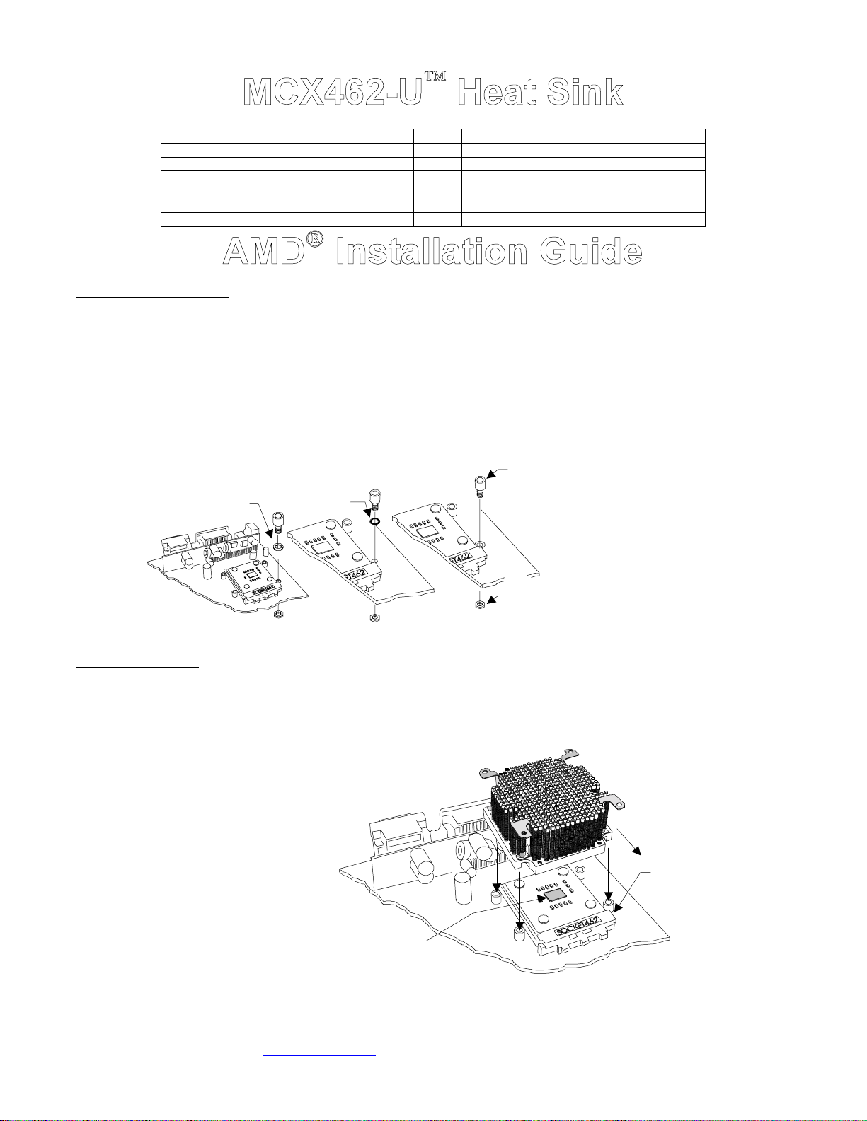
Determine which standoff washers to use, depending on your MB mounting holes:
• Large holes .230”(5.8mm) diameter : use .220x.046 Nylon spacers. The washers fit inside the MB hole.
• Small grounded holes .150”(3.8mm) diameter: you can recognize grounding by a silver ring around the holes; no washers
needed nor neces sary.
• Small holes, NOT grounded (bare c ircuit board): you must us e black fiber washers, or damage t o the MB may occ ur.
MB with
MB with
large holes
Use .220x.046
nylon spacer
MB with
small holes,
NOT grounded
Use black
Fiber washer
small holes,
grounded
No washer
necessary
Standoff
(fit inside the hole)
Nylon, hex nut
on back side of
the MB
3. Re-install the MB inside the case.
II. Heat sink Installation
1. The case should be laying flat on a table.
2. Insert the processor into the socket, and lightly coat the processor core with high quality thermal compound. Only a paper thin coat is
necessary. It should be applied using preferably a razor blade, or a credit card, held between thumb and index at a 45 degree angle. It is
critical to ascertain that the entire core is covered with a uniform coat of thermal compound. Thermal performance will dramatically
decrease if any portion of the core is not covered by thermal compound. We recommend Arctic Silver or similar high end compound for
superior thermal conductivity.
3. Place the bare MCX462-U heat sink
over the CPU as shown in the pic ture to
the right. The step side should be
located over the socket’s cam box. Keep
the heat sink mounting holes lined up
with the standoffs.
Ins tall standoff in each one of the
four holes surrounding the socket.
Keep the standoff & washer centered
over the MB holes, and secure with
nylon hex nuts on backside of the
MB. If you are going to
assemble/disas semble the heat sink
frequently, we recommend finishing
the installation by putting a drop of
“Crazy Glue “ at the junction between
standoff & MB, and between nylon
hex nut & MB. This will lock the
standoff onto the MB, and further
prevent it from spinning lose during
frequent assembly and disassembly
operations .
Step side
CPU core
Copyright Swiftech 2001 – All rights reserved – Last revision date: Oct. 2001
Rouchon Industries, Inc., dba Swiftech – 1703 E. 28
E Mail: Swiftech @swiftnets.com – URL: http://www.swiftnets.com
th
Street, Signal Hill, CA 90806 – Tel. 562-595-8009 – Fax 562-595-8769
This way
over cam box
Page 1
Information subject to change without notice
Page 2
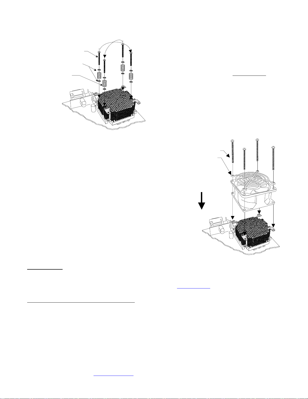
Crisscros
tightening
pattern
6-32 x 1 ½“
Philips screw
.230x.096
Nylon spacers
Spring
5. Fan Installation: Place the f an over the heat sink. The airflow should
be blowing down (fan label facing down). Place the fan guard over the
fan. Tighten the four 6-32 x 2” screws. The fan is equipped with two
connectors: a four pin molex connector which must be connected to
the power supply, and a 3 pin single wire connector which connects to
the MB fan sensor header.
6. Optional fan rheostat: a rheostat model # RH070 is sold separately,
and allows to adjust the fan speed. It connects between the fan power
connector and the power supply connector. Please consult your
distributor if you wish to purchase this item. Reducing the fan speed
reduces fan noise up to 9 dBA. It also reduces thermal performance,
and will affect overclocking performance accordingly. It is however
perf ectly appropriate f or non overclocked processor s.
4. Prepare 4 assemblies compos ed of (1) 1 ½”
screw, (2) .230x.096 Nylon spacers, and (1) spring
as shown in the picture to the left. Drop each
assembly in the heat sink mounting holes. While
gently press ing at the center of the heat sink, start
tightening the screws gradually in a crisscross
pattern until you feel that they reach the bottom of
the standoff. A “finger-tight” lock is sufficient.
Over tightening may result in stripping the nylon hex
nut. Conversely, adjustments such as tightening the
screws only partially are strictly prohibited
attempts will result in improper contact between the
CPU core and the heat sink, and result in CPU
overheating.
. Such
6-32 x 2“
Philips screw
Fan guard
Direction of
the flow
(fan label
facing down)
III. Final inspection
Now that the heat sink is installed, s tartup your computer, go into the BIOS and observe the C PU temperature. Under normal ambient
temperature c onditions, the processor temperature should never exc eed 55° C (130 ° F). If it does, shut down the computer immediately, and
review your entir e installation. Troubleshooting help is available on our web sit e at www.swiftnets.com
595-8009.
Uninstall note: CPU removal f rom some soc ket motherboar ds
Once in place, the standoffs may slightly interfere with CPU removal in some motherboards:
Depending on the manufacturers, sockets use either a plastic locking arm, or a metal locking arm. Sockets using a plastic locking arm require that
the arm be slightly pried open at the center in order to release it from its retaining tab. This can easily be done by inserting a thin screwdriver in
between the socket body and the arm’s mid-section, and by slightly twisting the screwdriver in either direction, while pulling on the arm. This will
slightly arch the mid-sec tion of the arm, and release it f rom its locking tab.
DISCLAIMER: Swiftech assumes no liability whatsoever, expressed or implied, for the use of these products.
Copyright Swiftech 2001 – All rights reserved – Last revision date: Oct. 2001
Rouchon Industries, Inc., dba Swiftech – 1703 E. 28
E Mail: Swiftech @swiftnets.com – URL: http://www.swiftnets.com
, or by calling customer support at 562-
th
Street, Signal Hill, CA 90806 – Tel. 562-595-8009 – Fax 562-595-8769
Information subject to change without notice
Page 2
Page 3
I. Preparing the motherboard
4. You must uninstall your M B prior to installing the MCX462-U heat sink.
5. Install standoffs in MB.
6. Re-install the MB inside the case.
II. Heat sink Installation
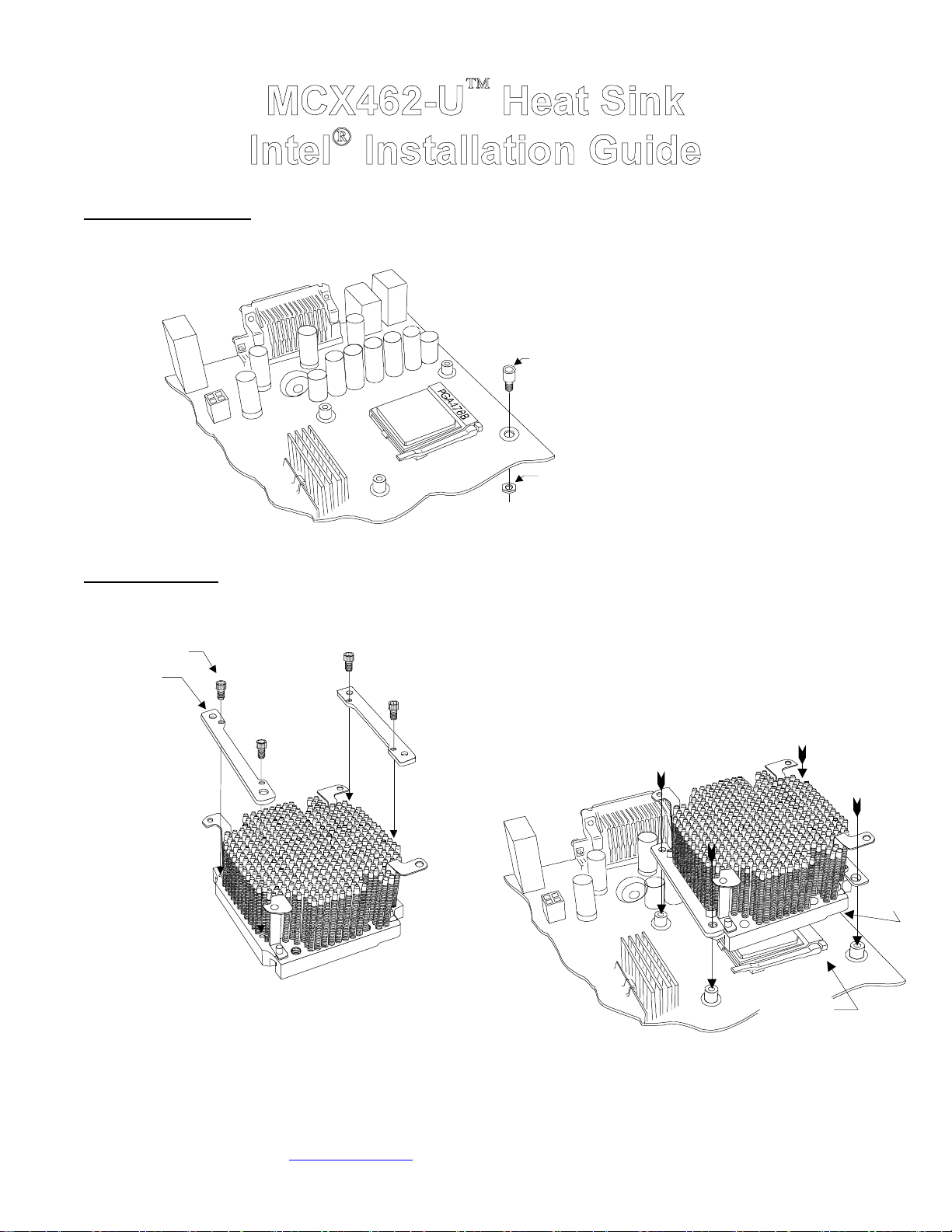
1. Install the two mounting brackets ont o the heat
4-40 x 1/4“
socket screw
sink, using the provided 4-40 x 1/4” socket screws:
Bracket
Do not install, or remove (if already
installed) Intel stock retention
mechanism (black plas tic f rame).
Ins tall standoff in each one of the four
holes surrounding the socket. Keep the
Standoff
Nylon, hex nut
on back side of
the MB
3. Insert the processor into the socket, and lightly coat the process or core
with high quality thermal compound. Only a paper thin coat is necessary.
It s hould be applied using preferably a razor blade, or a credit card, held
between thumb and index at a 45 degree angle. It is critical to ascertain that
the entire core is covered with a uniform coat of thermal compound. Thermal
performance will dramatically decrease if any portion of the core is not
covered by thermal compound. W e recommend Arctic Silver or similar high
end compound for superior thermal conductivity.
4. Place the bare MCX462-U heat sink over the CPU as s hown in the
pic ture below. T he s tep side should be located over the s ocket’s c am box.
Keep the heat sink mounting holes lined up with the standoffs.
standof f centered over the MB holes, and
secure with nylon hex nuts on backside of
the MB. If you are going to
assemble/disassemble the heat sink
frequently, we recommend finishing the
installation by putting a drop of “Crazy Glue
“ at the junction between standoff & MB,
and between nylon hex nut & MB. This will
lock the standoff onto the MB, and further
prevent it from spinning lose during
frequent assembly and disassembly
operations .
2. For the next step, the cas e should be laying flat on a
table
Copyright Swiftech 2001 – All rights reserved – Last revision date: Oct. 2001
Rouchon Industries, Inc., dba Swiftech – 1703 E. 28
E Mail: Swiftech @swiftnets.com – URL: http://www.swiftnets.com
th
Street, Signal Hill, CA 90806 – Tel. 562-595-8009 – Fax 562-595-8769
Socket
cam box
Page 3
Information subject to change without notice
Step
side
Page 4
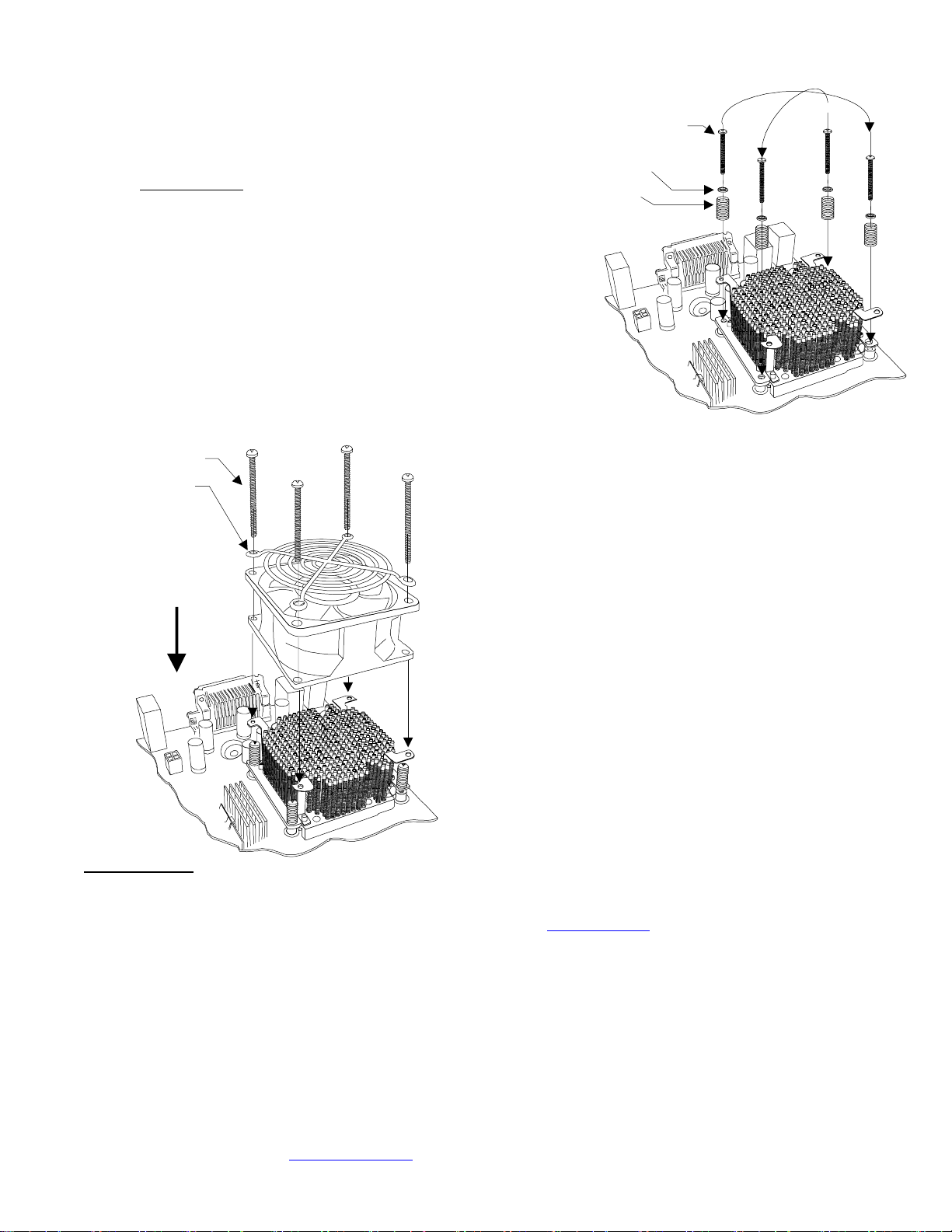
5. Prepare 4 assemblies compos ed of a 1 ½ ” s crew, 2 nylon flat washers,
and 1 spring as shown in the picture to the right. Drop each assembly in
the bracket mounting holes. While gently pressing at the center of the heat
sink, start tightening the screws gradually in a crisscross pattern until you
feel that they reach the bottom of the standoff. A “finger-tight” lock is
sufficient. Over tightening may result in stripping the nylon hex nut.
Conversely, adjustments such as tightening the screws only partially ar e
strictly prohibited
the CPU core and the heat sink, and result in CPU overheating.
. Such attempts will result in improper contact between
Criscross tightening pattern
6-32 x 1 ½“
Philips screw
Nylon flat
washer
Spring
6-32 x 1 5/8“
Philips screw
Fan guard
Direction of
the flow
(fan label
facing down)
III. Final inspection
Now that the heat sink is installed, s tartup your computer, go into the BIOS and observe the C PU temperature. Under normal ambient
temperature c onditions, the processor temperature should never exc eed 55° C (130 ° F). If it does, shut down the computer immediately, and
review your entir e installation. Troubleshooting help is available on our web sit e at www.swiftnets.com
595-8009.
DISCLAIMER: Swiftech assumes no liability whatsoever, expressed or implied, for the use of these products.
6. Fan Installation: Place the f an over the heat sink. The airflow should be
blowing down (fan label facing down). Place the fan guard over the fan.
Tighten the four 6-32 x 1 5/8” screws. The fan is equipped with two
connectors: a four pin molex connector which must be connected to the
power supply, and a 3 pin single wire connector which connects to the MB
fan sensor header.
7. Optional fan rheostat: a rheostat model # RH070 is sold separately, and
allows to adjust the fan speed. It connects between the fan power
connector and the power supply connector. Please consult your distributor
if you wish to purchase this item. Reducing the fan speed reduces fan
noise up to 9 dBA. It also reduces thermal performance, and will affect
overclocking performance ac cordingly. It is however perfectly appropr iate
for non over clocked pr ocessors .
, or by calling customer support at 562-
Copyright Swiftech 2001 – All rights reserved – Last revision date: Oct. 2001
Rouchon Industries, Inc., dba Swiftech – 1703 E. 28
E Mail: Swiftech @swiftnets.com – URL: http://www.swiftnets.com
th
Street, Signal Hill, CA 90806 – Tel. 562-595-8009 – Fax 562-595-8769
Page 4
Information subject to change without notice
 Loading...