

Page 1
Packing list
Parts Qty Parts Qty
Thermoelectric Heat Sink assembly 1 6-32 Hex Lock-Nuts (for
motherboard)
Snap-rivets (f or 80mm fan) 4 Black fiber washers (f or
motherboard)
Spring assembly – pre-installed 4 2 pole euro-style wire
connector
Standoffs 4 Thermal grease – Arctic
Alumina
.220x.046 Nylon spacers (for motherboard) 4 Motherboard gaskets 2
Preamble:
4
10
1
1
This product is intended for expert users only. Please consult with a qualified technician for installation. Improper installation may result in damage
to your components.
their installation.
I. Preparing the motherboard
1. You must uninstall your MB prior to installing the MCX462+ heat sink.
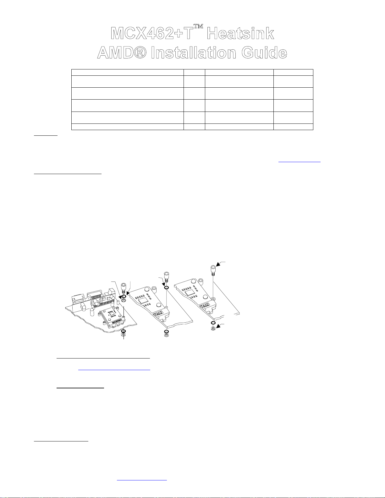
2. Install standoffs in MB
Determine which standoff washers to use, depending on the mounting holes sizes of your particular MB model:
• Large holes .230”(5.8mm) diameter, use in the following order: standoff, black fiber washer, .220x.046 Nylon spacers (fits inside the
• Small grounded holes .150”(3.8mm) diameter (you can recognize grounding by a silver ring around the holes), use in the following
• Small holes, NOT grounded (bare c ircuit board): you must us e black fiber washers, or damage to the MB may occ ur: us e in the
Swiftech assumes no liability whatsoever, expressed or implied, for the use of these products, nor
The following instructions are subject to change without notice. Please visit our web site at www.swiftnets.com for updates.
MB hole), then on the other side of the MB, black fiber washer, and lock-nut.
order: standoff directly to the MB (black fiber washer is NOT necessary), then on the other side of the MB, black fiber washer, and locknut.
following order: standoff, black fiber washer, then on the other side of the MB, black fiber washer, and lock-nut.
MB with
small grounded
holes, no washer
necessary on
this side
Standoff
MB with
large holes
Use .220x.046
nylon spacer
MB with
small
non-grounded
must use
fiber washer
holes
(fit inside the hole)
Ins tall standoff in each one of the
four holes surrounding the socket.
Keep the standoff & washer centered
over the MB holes, and secure with
hex lock nuts on backside of the MB.
Hex lock-nut
to back side of
the MB
Figure 1
• Fill-up the socket with dielectric grease:
the CPU. Dielectric grease is used to prevent condensation where parts are exposed to cold. We use Luberex (available on our web site
under the liquid cooling accessories section
Fill-up the socket center cavity (grease is to be level with the upper surface of the socket), and coat the socket pinholes with greas e.
Spread the grease with your finger so that it will penetrate inside the pinholes.
• Insert the processor
make sure that the processor is completely inserted into the socket. Apply paper-thin coat of thermal compound to processor core,
using a razor blade, or a credit card, held between thumb and index at a 45° angle. It is critical to ascertain that the entire core is covered
with a uniform coat of thermal compound. Thermal performance will dramatically decrease if any portion of the core is not covered by
thermal compound.
• Remove the peel-of f paper back of the motherboard gas ket, and install it as shown Fig. 2, s ticky side towards the motherboard.
• Apply the provided neoprene stic ker to the bac k of the motherboard as shown in Fig. 2
3. Install the MB inside the case..
II. Heat sink Installation
Copyright Swiftech 2002 – All rights reserved – Last revision date: Sep 11, 2002
Rouchon Industries, Inc., dba Swiftech – 1703 E. 28
E Mail: Swiftech @swiftnets.com – URL: http://www.swiftnets.com
into the socket. Since there is grease inside the socket, some hydraulic pressure lift may occur: for this reason,
Do not confuse dielectric grease with the provided thermal compound that is only used for
), but any similar product can be us ed, as long as it clearly s tates “ good dielectric properties ”.
th
Street, Signal Hill, CA 90755 – Tel. 562-595-8009 – Fax 562-595-8769
Information subject to change without notice
Page 1
Page 2
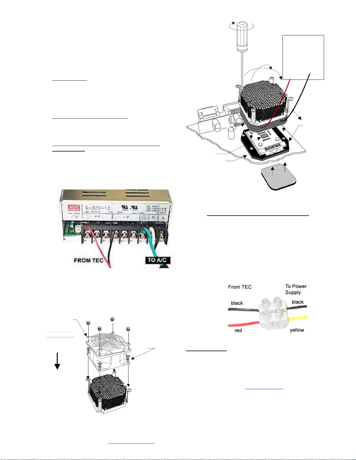
1. The case should be laying flat on a table.Install the
MCX462+T heatsink onto the CPU as shown in f ig. 2,
heats ink step s ide over the soc ket’s cam box. T ighten the
mounting screws in a crisscross pattern. Important note: Due
to wide variations in gasket thickness tolerances, we
suggest that you uninstall the heatsink once following the initial
assembly, just to verify that you have good contact between
cold plate and CPU. Inspect the grease imprint that the CPU
left on the copper plate: it should be perfectly even!
2. Fan installation:
! Use provided snap-rivets as shown in fig. 4 to secure fan to
heats ink.
! Recommended fans
Minimum 68cfm 80mm fans, such as but not limited to Delta
FFB0812SHE, FFB0812EHE, or Vantec 84cfm Tornado.
3. Thermoelectric module installation
! IMPORTANT WARNING: Solder joints of the wires to the
thermoelec tric module are extremely fragile. Bending the wires
at their root will break the solder joint, with no possible repair.
Swiftech will not honor the warranty for broken wires.
! Connection to a dedicated auxiliary power supply
(recommended):
# The TEC module is provided with “bare wires” to facilitate
installation with screw type terminals. We recommend the
“Meanwell S320-12” power supply, available on our website
in the liquid cooling accessories section. Connect red wire
from TEC module to the +V terminal, and black wire to the
–V terminal as shown in figure 3 below:
# Minimum requirements for a dedicated power supply: 20A
@ +12 V.
# If adjustable voltage is available: s etting the voltage higher
than +12V is not recommended. Lower voltage, can be
safely used, down to 9 volts.
:
Figure 3
Fan guard
and fan sold
Separately
TO POWER
Crisscros
tightening
pattern
SUPPLY
(min 20A at 12V)
Connect
Red wire
to +12 VDC
CPU core
MB gasket
Neoprene sticker
to back of MB
Figure 2
! Connection to an ATX computer power supply:
# Important Warning: to connect the MCX462+T cooler
to your computer power supply, you must carefully
consider the existing requirements of other devices
connected on the +12V line. Connecting to an
underpowered unit will definitely damage the power
supply.
#
Minimum requirements for an ATX computer power
supply: 28A at +12V in a typical setup.
#
Only use the provided euro-style wire connector
shown in fig 4 below. Connect red wire from TEC
module to +12V of P/S (Yellow wire), and black wire to
black wire:
Connect
black wire
to - VDC
Step side
This way
over
cam box
Direction of
the fan flow
(fan label
facing down)
Figure 4
Provided
Snap rivets
here
Copyright Swiftech 2002 – All rights reserved – Last revision date: Sep 11, 2002
Rouchon Industries, Inc., dba Swiftech – 1703 E. 28
E Mail: Swiftech @swiftnets.com – URL: http://www.swiftnets.com
th
Street, Signal Hill, CA 90755 – Tel. 562-595-8009 – Fax 562-595-8769
Figure 5
III. Final inspection
Now that the heat sink is installed, startup your computer, go into the
BIO S and obs erve the CPU temperature. Under normal ambient
temperature conditions, the proc essor temperature s hould never
exceed 55° C (130 ° F). If it does, shut down the computer
immediately, and review your entire installation. T roubleshooting help
is available on our web site at www.swiftnets.com
customer support at 562-595-8009.
DISCLAIMER: Swiftech assumes no liability whatsoever,
expressed or implied, for the use of these products.
, or by calling
Page 2
Information subject to change without notice
 Loading...