

Page 1

Hex lock-nut and
Parts
MCX4000 with TEC & gaskets assy.
Motherboard installation hardware pack
Fan retentions screws 1 ½” 4
Fan retention screws 2 ½” 4
This product is intended fo
damage to your components.
products, nor their instal
www.swiftnets.com
r expert users only. Please consult with a qualified technician for installation. Improper installation may result in
for updates
Swiftech Inc., 1703 E. 28th St., Signal Hill, CA 90755 T. (562) 595-8009 F. (562) 595-8769
Parts list
QTY PARTS
1
1
Swiftech assumes no liability whatsoever, expressed or implied, for the use of these
lation.
The following instructions are subject to change without notice. Please visit our web site at
Arctic Alumina Thermal compound
Euro-style connector
Fan retention screws 2 ¼” 4
1
1
QTY
1. Preparing the motherboard:
Remove the stock heatsink retention frame (the blac
clips down to your motherboard). This will reveal the four mounting
holes used to install the MCX4000-T retention standoffs.
Install a standoff in each one of the holes. Diameter of the mounting
holes is much larger than diameter o
standoff approximately centered in the MB holes, and secure them with
hex locknuts, and a fiber washer on backside of the MB.
k plastic frame that
f the standoff stem: keep the
Standoff
fiber washer
to backside of
the MB
Figure
1
Use a ¼” socket tool to drive the standoff, and a
prevent the locknut from spinning. Torque value should not to exceed
16 in. lbs.
small
pair of pliers to
Page 1 of 4
Figure
2
Page 2

Swiftech Inc., 1703 E. 28th St., Signal Hill, CA 90755 T. (562) 595-8009 F. (562) 595-8769
2. Condensation prevention:
Fill-up the socket with dielectric grease.
Do not c
onfuse dielectric grease with thermal compound. Dielectric
grease is used to prevent condensation where parts are exposed to
cold. We recommend Luberex (available on our web site under the
accessories section), or any similar product, with good dielectric
properties. Fill-up the socket center cavity (grease is to be level with
the upper surface of the socket), and coat the socket pinholes with
grease. Spread the grease with your finger so that it will penetrate
inside the pinholes.
Insert the processor
Figure
into the socket.
3
Figure
4
Remove the peel-off paper back from the motherboard gasket, and
install it as shown Figure 5.
motherboard.
The sticky side should be towards the
Since you have grease inside the socket, some hydraulic pressure lift
may occur: for this reason, make su
perfectly flat, and is inserted all the way into the socket. Then, coat
the processor core with high quality thermal compound.
paper-thin coat is necessary
a razor blade, or a credit card held between thumb and index at a 45
degree angle as shown on figure 4.
re that the processor sits
Only a
. It should be applied using preferably
-
Page 2 of 4
Figure
5
Page 3

Figure
Swiftech Inc., 1703 E. 28th St., Signal Hill, CA 90755 T. (562) 595-8009 F. (562) 595-8769
Install the MCX4000-T assembly onto your processor, as shown on
figure 6.
Gradually tighten the screws
th
Conversely, adjustments such as tightening the screws only partially are
strictly prohibited
the CPU core and the heat sink,
To further prevent condensation to occur behind the motherboard, a
neoprene sticker is provided with your MCX4000-T accessories
Apply it to the back of the motherboard, directly behind the
processor.
6
ey reach the bottom of the standoff. A “finger-tight” lock is sufficient.
. Such attempts will result in improper contact between
CRITICAL INSTRUCTIONS:
Never run a thermoelectric module without a fan.
This will result in catastro
element, and may cause any/all of the following:
permanent failure of the Peltier module
permanent damage to the CPU and/or
motherboard due to excess heat
in a crisscross pattern until you feel that
and result in CPU overheating.
phic failure of the cooling
.
Figure
7
Now, you can re-install the MB inside the case.
It is highly recommended
supply for the
supply. This will prevent the Peltier module to operate without a
fan.
For this purpose, we recommend the following accessory,
available in our online shopping cart:
PRS Kit II,
Includes:
Relay S
This relay switch is rated for
inrush
current. It is suitable for use with the S-320-12 Meanwell
power supply recommended in paragraph 3, page 4.
If you run
time, it is also a good practice to setup an alarm temperature,
which will shut down the computer in case the CPU overheats.
Such alarm/shut down process should be tested as functional.
thermoelectric module to the computer power
witch Circuit board AC socket, S/S socket cover, power cord
your computer unattended for extended periods of
that
you de
dicate the auxiliary power
110 to 220~240 volts and up to 50A
-
Page 3 of 4
Page 4
Swiftech Inc., 1703 E. 28th St., Signal Hill, CA 90755 T. (562) 595-8009 F. (562) 595-8769
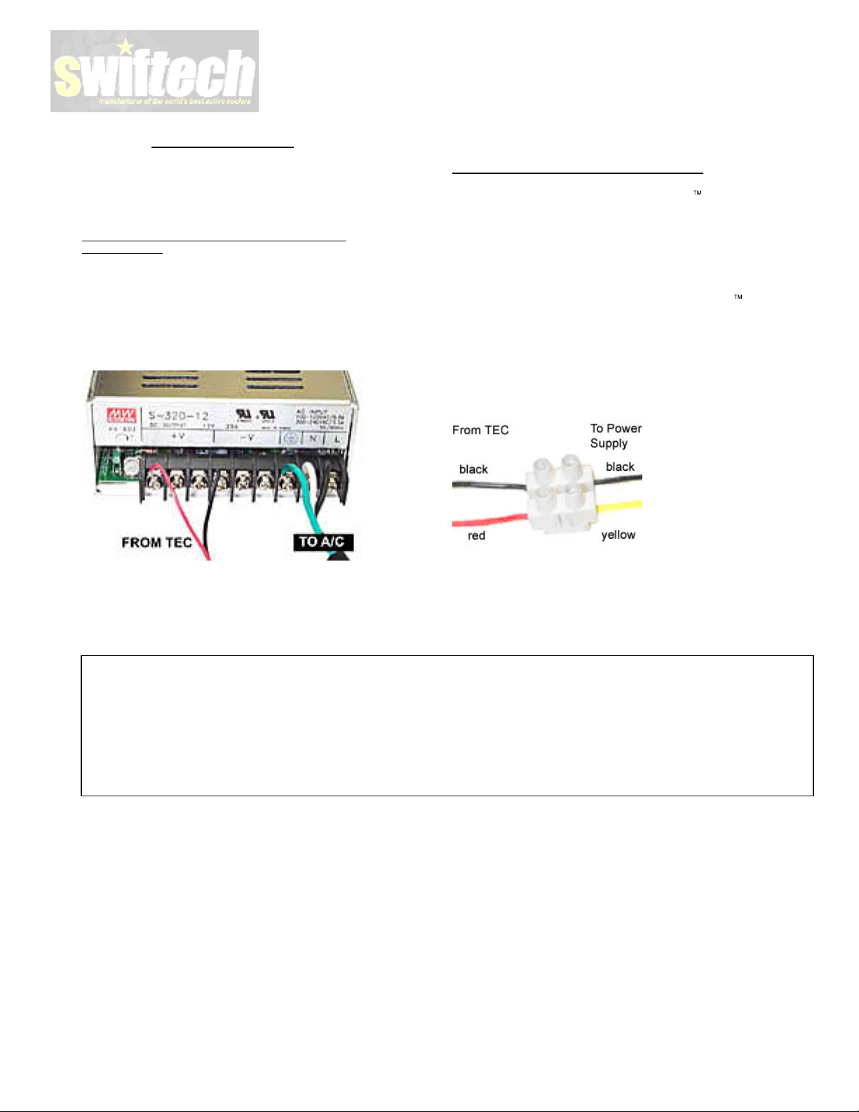
3. Thermoelectric installation
IMPORTANT WARNING:
thermoelectric module are
root will break the solder joint, with no possible repair.
not honor the warranty for broken wires
Connection to a dedicated auxiliary powe
(recommended):
The TEC module is provided with “bare wires” to facilitate installation
with screw type terminals. We recommend the “Meanwell S320-12”
power supply, available on our website in the Thermoelectric
accessories section.
Connect red
to the –V terminal as shown in figure 3 below:
wire from TEC module to the +V terminal, and black wire
Solder
joints of the wires to the
extremely fragile. Bending the wires at their
.
r supply
Swiftech will
Connection to an ATX computer power supply
Important Warning:
computer power supply, you must carefully consider the existing
requirements of other de
to an underpowered unit will definitely damage the power supply.
Minimum requirements for an ATX computer power supply: 37A at
+12V in a typical computer setup.
If you are nevertheless going to connect the
computer power supply, you need to cut the wiring to one of the power
supply Molex connectors, and use a different connector between power
supply, and thermoelectric. This is because Molex connectors are not
rated for 25 Amps current, and may o
Use a euro-style
device with a current rating of at least 25 amps. Connect red wire from
TEC module to +12V of P/S (Yellow wire), and black wire to black wire:
to connect the
vices connected on the +12V line. Connecting
wire connector as shown in fig 4 below, or similar
MCX4000-Tcooler to an ATX
verheat.
:
MCX
4000-Tto a
Minimum requirements for a dedicated power supply: 25A @ +12 V.
If adjustable voltage is available: setting the voltage higher than +12V
is not reco
volts
mmended. Lower voltage, can be safely used, down to 9
.
FAN R
ECOMMENDATIONS: THE MINIMUM RECOMMENDED AIRFLOW RATING IS 68CFM. FOR OPTIMUM PERFORMANCE, 80 CFM
IS PREFERRED.
AIR COOLED THERMOELECTRIC DEVICES REJECT A SIGNIFICANT AMOUNT OF HEAT INSIDE YOUR CASE. YOUR PROJECT
DESIGN SHOULD INCLUDE CAREFUL CONSIDERATI
DISCLAIMER: Swiftech assumes no liability whatsoever, expressed or implied, for the
ON TO CASE VENTILATION.
If you need wiring extension
the extension to the existing wires with
butts, and insulate with shrink tubing.
FINAL TIPS:
s: use 16 gage stranded wire.
use of these products.
terminal splices
, or solder the
Connect
Page 4 of 4
 Loading...