

Page 1
Compatible with AMD® Duron™, Athlon™, MP, XP 2000 & higher, and Intel® Pentium™ III processors
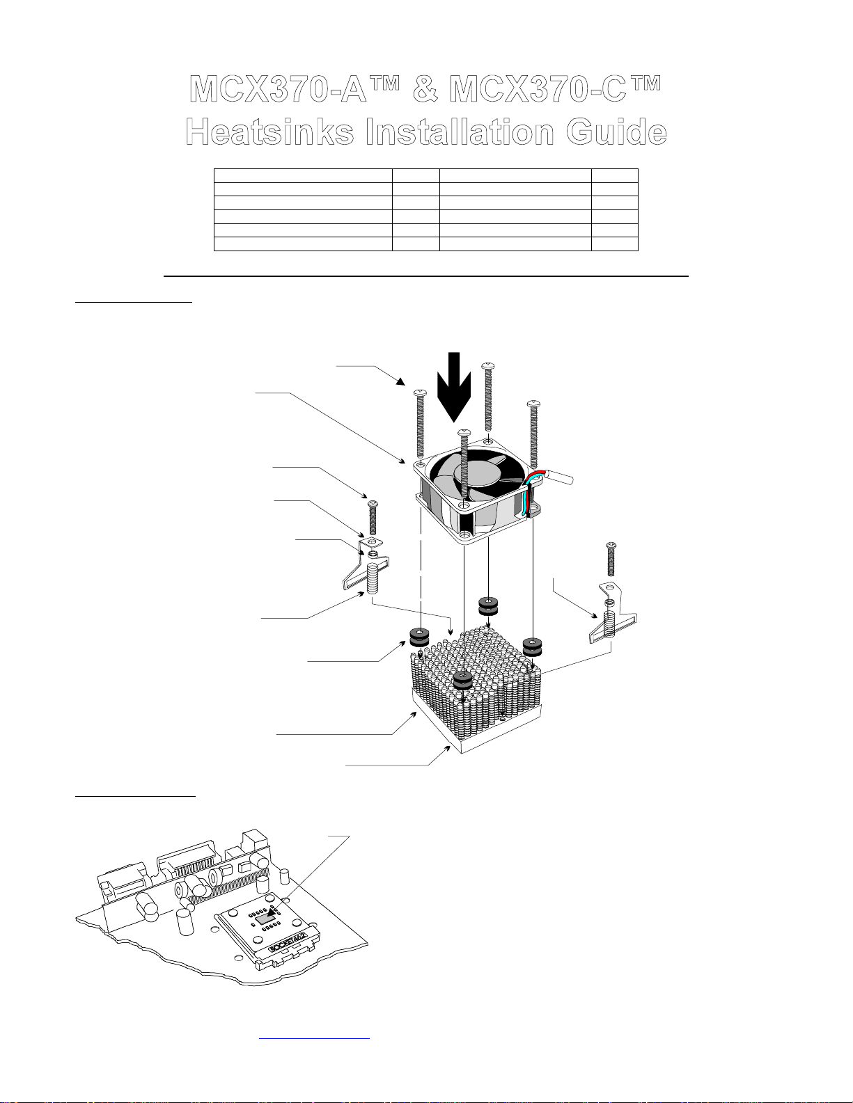
I. Assembly schematic
Packing list
Parts Qty Parts Qty
Heat Sink 1 Nylon spacers 2
Fan NO Long spring 1
6-32 x 2 ½ ” screws (for fan) 4 Short spring 1
6-32 x 1” screws (for HS) 2 Rubber washers 8
Clips 2 Thermal greas e 1
Fan ai r flow
direction
6-32 x 2 1/2“ screw
Fan
6-32 x 1 1/2“
screw
To power supply
Clip
II. Heat sink Installation
Nylon spacer
Long
spring
Rubber washer
Heat sink
Step in heat sink base
Thermal compound
here
Short
spring
• We recommend that you lay down your computer flat on a table.
• Lightly coat the processor core with the included thermal compound.
Only a paper thin coat is necessary. It should be applied using
pref erably a razor blade, or a credit c ard, held bet ween thumb and
index at a 45 degree angle. It is critical to ascertain that the entire core
is covered with a uniform coat of thermal compound. Thermal
performance will dramatically decrease if any portion of the core is not
covered by thermal compound.
Copyright Swiftech 2001 – All rights reserved – Last revision date: Oct. 2001
Rouchon Industries, Inc., dba Swiftech – 1703 E. 28
E Mail: Swiftech @swiftnets.com – URL: http://www.swiftnets.com
th
Street, Signal Hill, CA 90806 – Tel. 562-595-8009 – Fax 562-595-8769
Page 1
Information subject to change without notice
Page 2
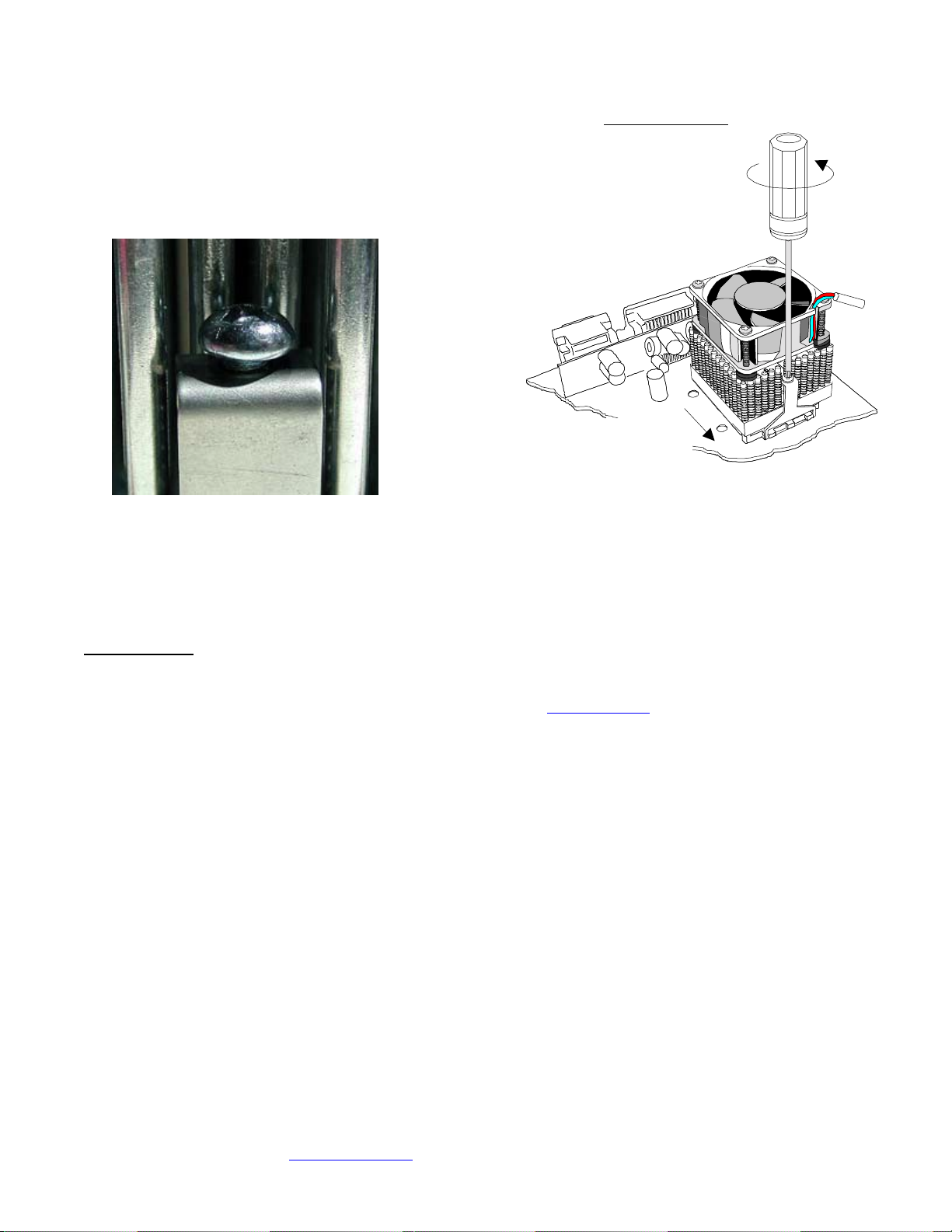
• The heat s ink bas e features a s tep which should be placed over the
socket’s c am box as s hown in schematic to the right.
• Plac e the heat s ink fan assembly onto the CPU making sure that the clips
hook to the tabs on each side of the socket. Should the factory setting be a
little short, do not attempt to force the heat sink down by rocking it one side
or another. Simply sc rew cloc kwise until the clips hook onto the tabs.
Turn screw driver
counter clockwise
to
secure assy.
To CPU
• Then, turn both screws counter-clockwise until the head of the screw
clears the top of the clip by approximately 1/16” (1.5mm) as shown in the
pic ture below. As s oon as the head of the sc rew is no longer touching the
top of the clip, the spring is under full tension.
Step side
over socket
cam box
• Note: Should you disassemble the mounting screws and compression
• Finally, connect the fan power cord to the power supply.
III. Final inspection
DISCLAIMER: Swiftech assumes no liability whatsoever, expressed or implied, for the use of these products.
springs for any reason in the future, pleas e note that the springs are of
unequal length. The short spring goes on the side of the heat sink that
features a step in the base, whereas the long spr ing goes to the opposite
side (s ee assy. schematic on page 1).
Now that the heat sink is installed, s tartup your computer, go into the BIOS and observe the C PU temperature. Under normal ambient
temperature c onditions, the processor temperature should never exc eed 60° C (140 ° F). If it does, shut down the computer immediately, and
review your entir e installation. Troubleshooting help is available on our web sit e at www.swiftnets.com
595-8009.
, or by calling customer support at 562-
Copyright Swiftech 2001 – All rights reserved – Last revision date: Oct. 2001
Rouchon Industries, Inc., dba Swiftech – 1703 E. 28
E Mail: Swiftech @swiftnets.com – URL: http://www.swiftnets.com
th
Street, Signal Hill, CA 90806 – Tel. 562-595-8009 – Fax 562-595-8769
Page 2
Information subject to change without notice
 Loading...