

Page 1
Packing list
Parts Qty Parts specific to AMD installations Qty Parts specific to AMD installations Qty
Heat Sink 1 AMD Brackets 2 Black fiber washers 6
40mm fan & screws 1 4-40 x 3/16” socket screws 2 Nylon spacers 2
Wire-Springs 2 4-40 x 1 ¼” Philips screws and
mini-nuts
Thermal grease – Arctic Céramique 1 Nylon tensions limiters 2 Springs 2
Neoprene pads (strip of 4) 1 Hex wrench 1 4-40 x 3/8” socket screws 2
Pre-installation Notes
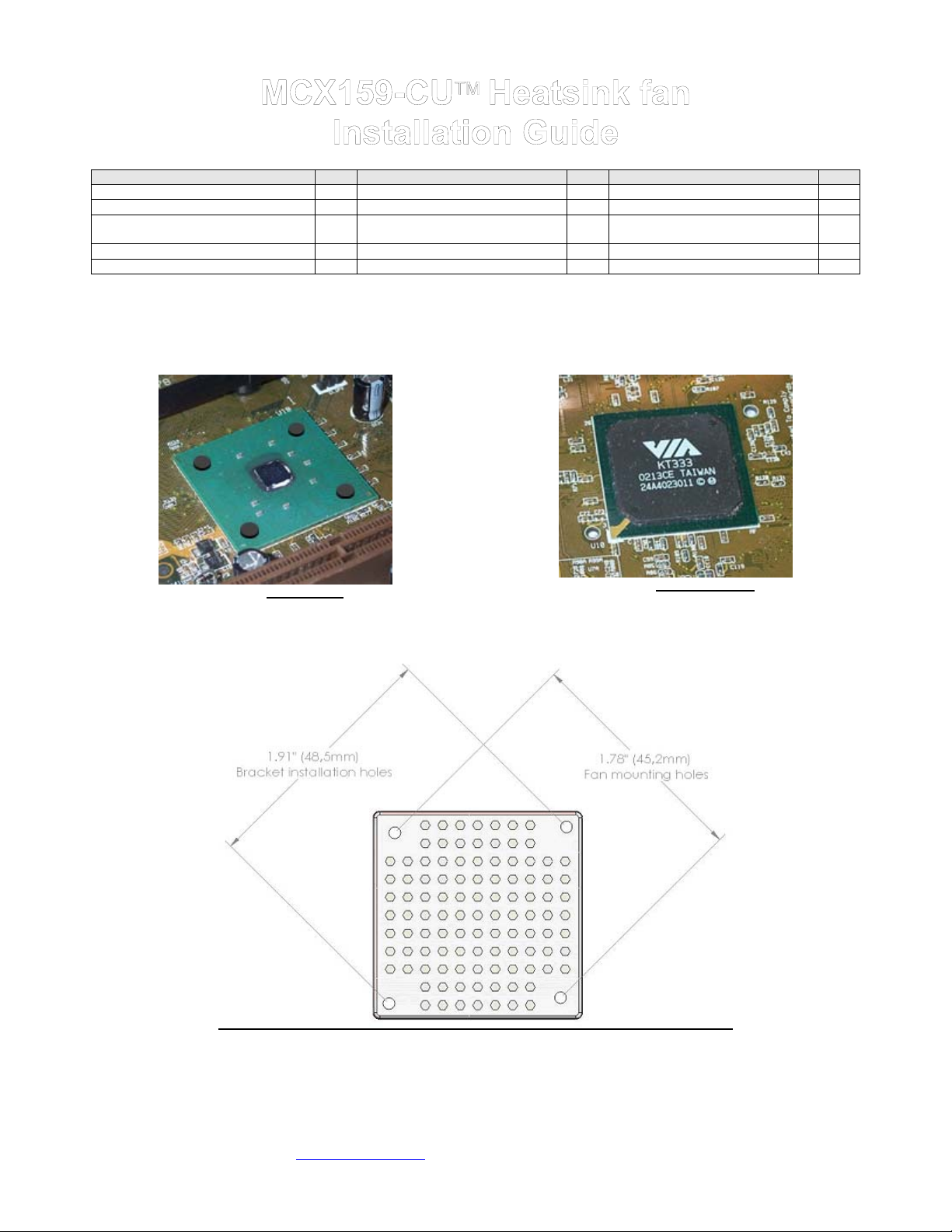
a. The MCX159-CU ships with 4 small neoprene pads. These are used for two purposes: stabilize the heatsink, and minimize the risk of
damaging the processor core upon installation. These pads must be removed when installed on chipsets protected by a heat spreader. Below
are examples or when to use the pads, and when NOT to use the pads:
2 Knurled knobs 2
Figure 1 - Pads needed
b. The bracket installation and fan mounting holes are spaced differently. Be careful to use the right holes for the correct purpose as
shown below:
Figure 2 - Pads not needed
Figure 3
Copyright Swiftech 2005 – All rights reserved – Last revision date: 8-16-05
Rouchon Industries, Inc., dba Swiftech – 1703 E. 28
E Mail: Swiftech @swiftnets.com – URL: http://www.swiftnets.com
th
Street, Signal Hill, CA 90755 – Tel. 562-595-8009 – Fax 562-595-8769
Page 1
Information subject to change without notice
Page 2
1. Heatsink fan Installation for Motherboards equipped with wire loops (Intel Platforms)
Installation does not necessitate removal of the motherboard from the chassis.
Remove the existing heatsink and carefully clean the microprocessor with alcohol
Lightly coat the CPU with the provided Céramique™ thermal compound. Follow this link
http://www.arcticsilver.com/ceramique_instructions.htm
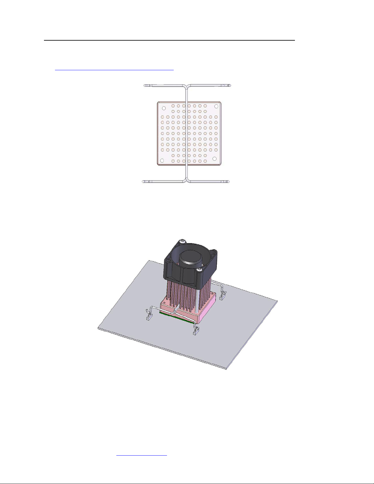
Remove the fan from the heatsink, and engage both wire-clips in the centermost row of pins as shown below:
for detailed instructions.
Figure 4
Re-install the fan onto the heatsink.
Apply the provided neoprene pads onto the chipset if applicable (see figures 1 and 2 page 1)
Fasten the heatsink onto the chipset as shown below by simply engaging one end of the hook into a motherboard retention
loop then engaging the opposite hook, and repeating the process for the second clip. Then, make sure to center the heatsink
between the arms of the wire-clips.
Figure 5
Finally, connect the fan to an available 3-pin power connector on the motherboard. Note that this fan does not feature an RPM
sensor. If applicable, you should therefore turn-off the Bios monitoring functions for the header in use with this fan.
Installation is complete!
Copyright Swiftech 2005 – All rights reserved – Last revision date: 8-16-05
Rouchon Industries, Inc., dba Swiftech – 1703 E. 28
E Mail: Swiftech @swiftnets.com – URL: http://www.swiftnets.com
th
Street, Signal Hill, CA 90755 – Tel. 562-595-8009 – Fax 562-595-8769
Page 2
Information subject to change without notice
Page 3
2. Heatsink fan installation thru motherboard holes (mostly AMD, some Intel platforms)
2.1 Pre-installation steps
Installation of the heatsink always necessitates removal of the motherboard from the chassis.
Remove the existing heatsink and carefully clean the microprocessor with alcohol
Apply the provided neoprene pads onto the chipset if applicable (see figures 1 and 2 page 1)
2.2 Installation of the mounting posts
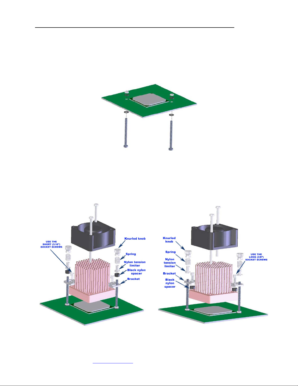
Follow Figure 6 below to install the retention posts: install two 4-40 x 1.25” Philips screws with fiber washers on both sides of the
motherboard, and secure them with the provided 4-40 mini-nuts.
Figure 6
2.3 Heatsink assembly
Please refer to figure 3 page 1 to identify the adequate mounting holes for the brackets.
The heatsink brackets can be installed in two different fashions to allow more or less clearance with neighboring components:
a. Bracket will be attached directly onto the heatsink as shown in figure 7.
b. A spacer will be placed between the bracket and the heatsink to position the bracket higher, and allow clearance for capacitors
in some motherboards (Asus A8N-SLI for example), as shown in figure 8.
c. To determine which of the above will be used, simply place the heatsink on the chipset, and visually identify possible clearance
issues.
Figure 7
Copyright Swiftech 2005 – All rights reserved – Last revision date: 8-16-05
Rouchon Industries, Inc., dba Swiftech – 1703 E. 28
E Mail: Swiftech @swiftnets.com – URL: http://www.swiftnets.com
th
Street, Signal Hill, CA 90755 – Tel. 562-595-8009 – Fax 562-595-8769
Figure 8
Page 3
Information subject to change without notice
Page 4

2.4 Fasten the heatsink to the motherboard
Lightly coat the CPU with the provided Céramique™ thermal compound. Follow this link
http://www.arcticsilver.com/ceramique_instructions.htm
Fasten the heatsink to the motherboard as shown in figure 7 or figure 8 as appropriate. Gently tighten the knurled knobs
incrementally until resistance from the tension limiter is felt.
Finally, connect the fan to an available 3-pin power connector on the motherboard. Note that this fan does not feature an RPM
sensor. If applicable, you should therefore turn-off the Bios monitoring functions for the header in use with this fan.
Re-install the motherboard into chassis.
for detailed instructions.
Installation is complete!
IMPORTANT DISCLAIMER: While all efforts have been made to provide the most comprehensive tutorial possible, Swiftech assumes no
liability expressed or implied for any damage(s) occurring to your components as a result of using Swiftech cooling products, either due to
mistake or omission on our part in the above instructions, or due to failure or defect in the Swiftech cooling products.
WARRANTY: Our products are guaranteed for 12 months from the date of delivery to the final user against defects in materials or
workmanship. During this period, they will be repaired or have parts replaced provided that: (I) the product is returned to the agent from which
it was purchased; (II) the product has been purchased by the end user and not used for hire purposes; (III) the product has not been misused
(*), handled carelessly, or other than in accordance with any instructions provided with respect to its use. This guarantee does not confer rights
other than those expressly set out above and does not cover any claims for consequential loss or damage. This guarantee is offered as an
extra benefit and does not affect your statutory rights as a consumer.
Copyright Swiftech 2005 – All rights reserved – Last revision date: 8-16-05
Rouchon Industries, Inc., dba Swiftech – 1703 E. 28
E Mail: Swiftech @swiftnets.com – URL: http://www.swiftnets.com
th
Street, Signal Hill, CA 90755 – Tel. 562-595-8009 – Fax 562-595-8769
Page 4
Information subject to change without notice
 Loading...