

Page 1

Copyright Swiftech 2005 - All rights reserved - Last revision date: 05-09-06 - One or more Patents Pending
Rouchon Industries, Inc., dba Swiftech - 1703 E. 28th Street, Signal Hill, CA90755 - Tel. 562-595-8009 - Fax 562-595-8769 E Mail: Swiftech@swiftnets.com - URL: http://www.swiftnets.com - Information subject to change without notice
MMMMCCCCWWWW66660000 VVVVGGGGAAAA CCCCOOOOOOOOLLLLIIIINNNNGG
GG
IIIINNNNSSSSTTTTAAAALLLLLLLLAAAATTTTI
IIIOOOONNNN GGGGUUUUIIIIDDDDEE
EE
Thank you for purchasing the MCW60 VGA cooling system. This product is intended for expert users. Please consult with a qualified
technician for installation. Improper installation may result in damage to your components. Swiftech™ assumes no liability whatsoever,
expressed or implied, for the use of this product, nor its installation. The following instructions are subject to change without notice.
Please visit our web site at www.swiftnets.com for updates.
Overview
The MCW60 is shipped with a pre-assembled hold-down plate compatible with all nVidia High-end GeForce and ATI Radeon using a
four-hole fastening system. Mid-range ATI products using a 2-hole bolt-down are also compatible by using the included haldware.
Please refer to our product page for further information.
1/ ATI 2-hole bolt-down ONLY: pre-installation steps
You will need to remove the chrome hold-down plate as shown below, before you can install the product with ATI 2-hole boards. Once
done, please follow the steps common to all VGA adapters, and the installation schematic provided page 2.
2/ Common Installation steps to all graphics cards
General information
• The MCW60 VGA water-block may be installed in any direction.
• The inlet and outlet are interchangeable with respect to flow direction.
• Coolant: use of distilled water is mandatory. Swiftech's HydrX coolant is recommended as an antifungal, and corrosion
inhibitor.
BEFORE INSTALLATION:
• Install the barb fittings with their o-rings into the water-block before you fasten the water-block to the VGA card. The MCW60
is shipped with 2 sets of fittings in the US: 1/2” barbs, and 3/8” barbs, and an additional set of 1/4” barbs in Europe.
• Tighten each fitting until the flange of the fitting mates with the ledge of the water-block o-ring groove, then lock it by
adding ¼ to ½ turn.
• Remove the existing cooling solution from the graphics card, and carefully clean off the GPU with an electronics degreaser.
• Apply the provided Arctic Céramique thermal compound to the GPU following the comprehensive installation instructions pro-
vided here: http://www.arcticsilver.com/ceramique_instructions.htm
• Install the MCW60 water-block following the individual installation schematic for the type of GPU setup correponding to your
VGA adapter and provided page 2 and 3 hereafter.
AFTER INSTALLATION:
• Connect the tubing to the water-block hose-barbs. Use the provided hose-clamps to secure the tubing to the barbs. Always
test your setup extensively for leaks before you energize the graphics card!
4 -holes setup
Remove all four screws
with the provided Hex
key, and set aside the
chrome hold-down plate,
as it will not be needed.
Re-install the four screws, using the provided lock-washers. Your water-block is now
ready to use with ATI 2-hole bolt pattern.
2-holes setup
Page 2
Copyright Swiftech 2006 - All rights reserved - Last revision date: 05-09-06 - One or more Patents Pending
Rouchon Industries, Inc., dba Swiftech - 1703 E. 28th Street, Signal Hill, CA90755 - Tel. 562-595-8009 - Fax 562-595-8769 E Mail: Swiftech@swiftnets.com - URL: http://www.swiftnets.com - Information subject to change without notice
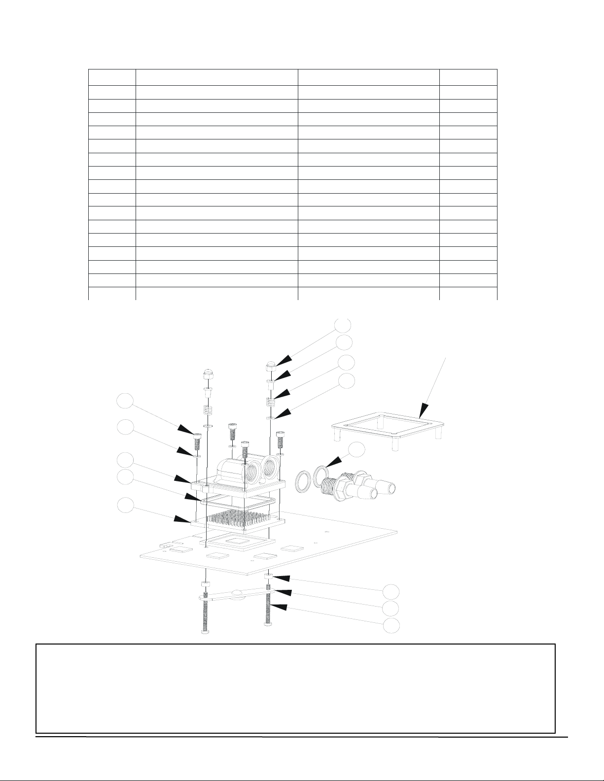
Installation with ATI Radeon (2 mounting holes)
ITEM
PART NUMBER
DESCRIPTION
QTY
.
1
mcw60-housing-rev2 1
2
MCW60 BASE PLATE 1
3
O-RING_3-32
Body o-ring
1
4
1-4-NPSMx3-8-barb
1/4" NPSM X 3/8" Barb fitting
2
5
O-RING-9557K473
1-4'" NPSM barb fitting O-Ring
2
6
92196A146 6-32 x 5/8 socket screw 4
7
stiffening-bar
1
8
4-40x1-25-philips-91400A124
4-40 x 1.25 philips screw
2
9
70700S
spring
2
10
X800-XT 1
11
13ME028
Nylon metric flat washer
2
12
4-40-acorn-nut
Nylon Nut 4-40 - 0500440CN
2
13
washer-240x140x0038 2
14
SCREW INSULATOR10SC004025 2
15
LOCK-WASHER#6
#6 lock washer x 0.030"
4
16 MCW60-HDP-R2 WCW60 HOLD-DOWN PLATE R2
1
17 - Discard
12
14
9
13
6
15
1
3
2
11
7
8
5
• Remove the existing heatsink
• Clean off the GPU with a degreaser, and spread some of the included thermal compound over it.
• Install the MCW60 onto the GPU
• Install screws #8, back-plate #7 and nylon spacers #11 thru the circuit board and the MCW60 water-block.
• Install washers #13, springs #9, compression limiter #9 and acorn nut #12, then gradually and alternatively fasten acorn
nuts (#12) until they bottom out.
• Installation of the water-block is now complete.
Page 3
Copyright Swiftech 2006 - All rights reserved - Last revision date: 05-09-06 - One or more Patents Pending
Rouchon Industries, Inc., dba Swiftech - 1703 E. 28th Street, Signal Hill, CA90755 - Tel. 562-595-8009 - Fax 562-595-8769 E Mail: Swiftech@swiftnets.com - URL: http://www.swiftnets.com - Information subject to change without notice
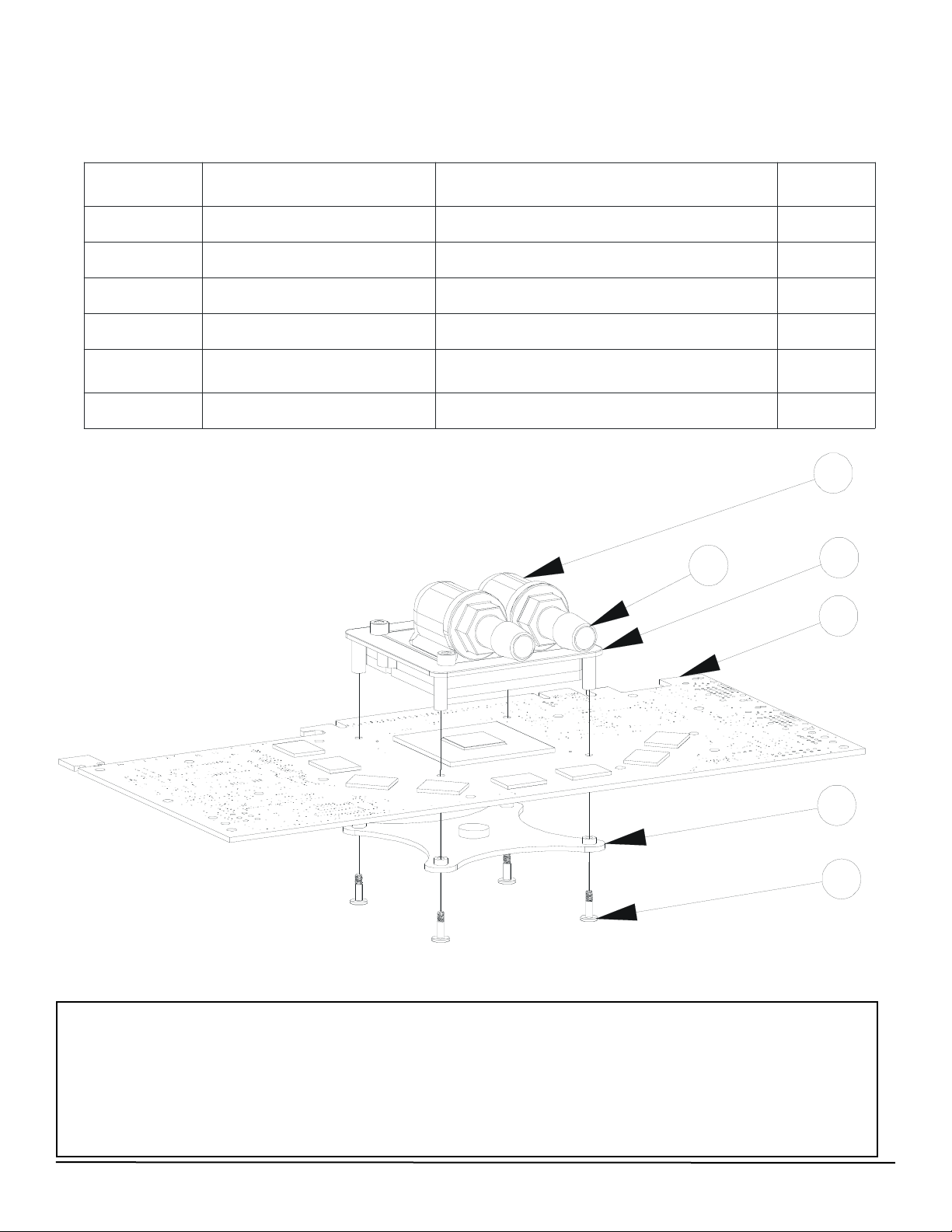
Installation with nVidia GeForce 6800 to 7900 series
& ATI X1800 and above
(four mounting holes)
ITEM NO. PART NUMBER DESCRIPTION QTY
.
1MCW60 WATER-BLOCK 1
2 1-4-NPSMx3-8-barb 1/4" NPSM X 3/8" Barb fitting 2
3 MCW60-HDP-R2 MCW60 HOLD-DOWN PLATE R2 1
4 MCW60-CB-R2 MCW60 CROSS-BRACKET R2 1
5 MCW60-2-56-PFH-CS 2-56 CUSTOM SCREW 4
6 REFERENCE VGA ADAPTER 1
1
3
2
6
4
5
• Remove the existing heatsink
• Clean off the GPU with a degreaser, and spread some of the included thermal compound over it.
• Position the MCW60 over the GPU, aligning the 4 feet of the hold-down plate to the circuit board thru-holes
• Insert screws #5 thru cross-bracket #4, thru the circuit board, and fasten them into the legs of hold-down plate #3,
tightening the screws gradually and in a cross pattern.
• Installation of the water-block is now complete
Page 4
Copyright Swiftech 2006 - All rights reserved - Last revision date: 05-09-06 - One or more Patents Pending
Rouchon Industries, Inc., dba Swiftech - 1703 E. 28th Street, Signal Hill, CA90755 - Tel. 562-595-8009 - Fax 562-595-8769 E Mail: Swiftech@swiftnets.com - URL: http://www.swiftnets.com - Information subject to change without notice
Fittings compatibility notes:
The provided fittings thread is 1/4” NPSM. This thread is compatible with BSPP and G 1/4 threads.
G ¼, or BSPP fittings will fit, but may not necessarily seal properly; each must be checked prior to assuming that it will not leak just
because they fit together. Both NPSM and G ¼ (BSPP) are parallel thread and nominally the same size, the principal difference being
18 threads per inch for NPSM and 19 threads per inch for G ¼ (BSPP). Since most male end G ¼ fittings have a short thread length
they can generally be engaged in the NPSM threads without difficulty. The joint seal is effected with an o-ring which for the NPSM
barb is in a groove on the waterblock top and compressed by the flange nut barb. G ¼ fittings have the o-ring captured in a groove
under the fitting nut. G ¼ fittings will seal so long as there is a straight portion under the nut flats sufficient to bring the G ¼ fitting’s oring into contact with the bottom of the waterblock o-ring groove, a depth of 0.080”.
ALWAYS CHECK YOUR CIRCUIT FOR LEAKS PRIOR TO POWERING-UP YOUR COMPONENTS!
Installation of the MC14 BGA Ramsinks
Common steps:
1. Remove the existing memory heatsink
2. Carefully clean-off the BGA modules with an electronics degreaser
Plug-and-play installation
1. Peel-off the protection paper from the MC14 Ramsink
2. Firmly press the Ramsink onto the BGA module for 5 to 10 seconds. Installation is complete.
Advanced Installation
For a superior mechanical joint and enhanced thermal conductivity, the MC14 Ramsinks may be permanently attached to the
memory modules using a thermally conductive epoxy glue such as Arctic Alumina or Arctic Ceramique Epoxy. Non electrically conductive or non-capacitive glue should be used to prevent damage to the memory, thus precluding the use of Arctic Silver Epoxy
which is capacitive. Please refer to http://www.arcticsilver.com for installation guidelines.
Please note again that such installation is permanent and will void your Warranty
1. Peel-off the protection paper from the MC14 Ramsink, and carefully clean off the thermal adhesive with a solvent
2. Carefully clean-off the BGA modules with an electronics degreaser
3. Apply a small amount of epoxy glue to the memory modules.
3. Gently rub the MC14 ramsink on the BGA module in a circular motion in order to spread the epoxy evenly
4. Allow the epoxy to dry following manufacturer instructions.Installation is complete.
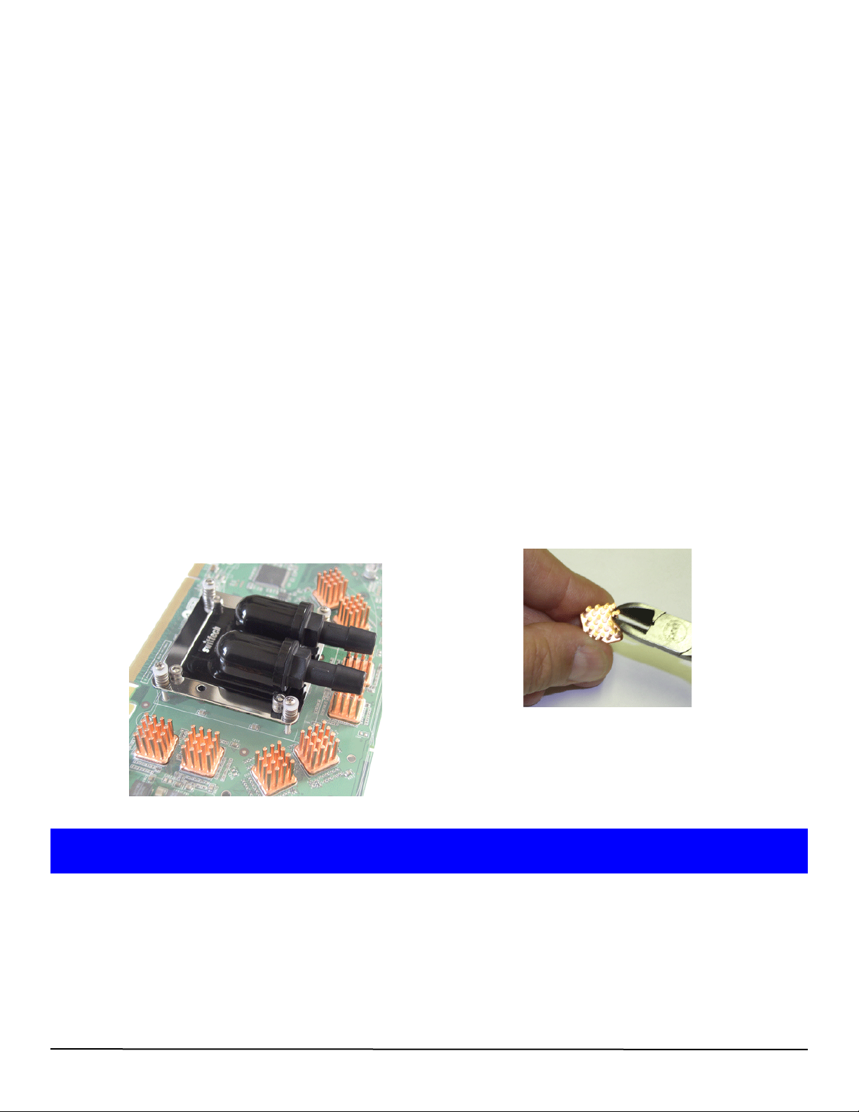
Installation issues with 1/2” barbs and 3/4” or 5/8” OD tubing.
In some instances, there may not be sufficient clearance to install the Ramsinks on the memory modules located directly under
the water-block inlet and outlet when using the above mentioned tubing. This issue does not affect smaller diameter tubing such as
3/8” and 1/4” (1/2” OD and 3/8” OD). The pins of two of the memory Ramsinks can be easily shortened to provide clearance.
Simply use a small pair of pliers, and cut the pins individually as shown below:
Installation is complete !
 Loading...