

Page 1

MMMMEE--112200772233
USER
’’
S MANUAL
MAN-12 Automatic
Embroidery Machine
SSuunnSSttaarr CCOO..,, LLTTDD..
Page 2

Page 3

1. This manual explains and describes the operation methods and
related issues of “Automatic Embroidery Machine” to
ensure the proper use. Please have a thorough understanding of
the manual before operating the machine.
2. The manual is subject to change without prior notice to enhance
the quality of the embroidery machine and may be different a bit
from the purchased product. If you have any inquiry on the product
and manual, please contact a sales agency.
3. The manual must be passed on to next users.
Page 4

4
Contents
1. MACHINE TYPES AND SPECIFICATIONS
...................................................................................
6
1.1) MACHINE TYPES
.................................................................................................................................
6
1.2) MODELS
................................................................................................................................................
6
1.3) SPECIFICATIONS
..................................................................................................................................
6
1.4) PERIPHERALS
.......................................................................................................................................
6
2. SAFETY RULES
.......................................................................................................................................
7
2.1) SAFETY INDICATIONS
.......................................................................................................................
7
2.2) MACHINE DELIVERY
.........................................................................................................................
8
2.3) MACHINE INSTALLATION
................................................................................................................
9
2.4) MACHINE OPERATION
.......................................................................................................................
9
2.5) REPAIR
................................................................................................................................................
10
3. PRODUCT FEATURES
........................................................................................................................
11
4. MACHINE INSTALLA TION AND PRECAUTIONS
...................................................................
13
4.1) INSTALLATION CONDITION
...........................................................................................................
13
4.2) ELECTRICITY INSTALLATION ENVIRONMENT
.......................................................................
14
4.3) LEVELING THE MACHINE
..............................................................................................................
14
5. MACHINE USE AND PRECAUTIONS
...........................................................................................
16
5.1) TYPES OF SAFETY LABELS
............................................................................................................
16
5.2) LOCATIONS OF SAFETY LABELS
.................................................................................................
17
6. NAMES OF MACHINE PARTS
.........................................................................................................
18
7. PERIPHERALS ASSEMBLY
.............................................................................................................
19
7.1) STAND ASSEMBLY (Optional)
..........................................................................................................
19
7.2) CHANGE CAP TO TUBULAR
...........................................................................................................
19
8. BASIC FUNCTIONS FOR MACHINE OPERATION
.................................................................
21
8.1) BASIC OPERATION
............................................................................................................................
21
8.2) NEEDLE-HOOK TIMING AND RELATED TIPS
...........................................................................
33
8.3) THREAD DETECTOR ASSEMBLY AND FUNCTIONS
...............................................................
39
8.4) COVER ASSEMBLY
...........................................................................................................................
40
Page 5

5
Contents
9. MAINTENANCE AND INSPECTION
..............................................................................................
43
9.1) CHECK POINTS FOR REGULAR INSPECTION
............................................................................
43
9.2) CLEANING
...........................................................................................................................................
43
9.3) OIL SUPPLY
.........................................................................................................................................
45
10. ADJUSTING MAJOR PARTS OF THE MACHINE
.................................................................
50
10.1) TRIMMER ADJUSTMENT
..............................................................................................................
50
10.2) ADJUSTING UPPER THREAD HOLDER
.....................................................................................
51
10.3) ADJUSTING LOW-NOISE PRESSER FOOT
.................................................................................
51
10.4) RELATIONSHIP BETWEEN PRESSER FOOT AND NEEDLE
..................................................
53
10.5) ADJUSTING HALF-TURN FILM
....................................................................................................
54
10.6) ADJUSTING ENCODER
...................................................................................................................
55
10.7) ADJUSTING JUMP SOLENOID
......................................................................................................
56
10.8) ADJUSTING TENSION OF EACH DRIVE BELT
.........................................................................
57
11. TROUBLESHOOTING
.......................................................................................................................
59
11.1) CAUSES AND TROUBLESHOOTING
...........................................................................................
59
11.2) ERROR DISPLAY AND TROUBLESHOOTING
...........................................................................
70
12. SETTING
.................................................................................................................................................
74
Page 6
6
MACHINE TYPES AND SPECIFICATIONS
01
1.1) MACHINE TYPES
1.2) MODELS
1.3) SPECIFICATIONS
Machine
MAN-12
HeadColor
Semi-Wide Cap FrameWide Cap FrameTubular
360×230 360×75 180×83
Emb. space (X,Y)
12
1
Stitch Length 0.1~12.7mm
Speed Max. 1000 rpm
Motor
BLDC Motor×1 (Main Shaft Motor)
Pulse Motor×2 (Frame Driving Motor)
Electricity 1-Phase : 100V, 110V, 120V, 200V, 220V, 240V (50~60 Hz)
Power Consumption 700W
1.4) PERIPHERALS
Bobbin Winder Standard
Memory Capacity Max. 10,000,000
Memory Medium USB Memory Stick
Hook 1.7 Fold Capacity Hook (Option)
Device (Option) Boring Device, Stand, Cap Frame, Laser Point, Bobbin Winder
M A N - 12
Mother
Series
New Network System
No. of Needles
Page 7
SAFETY RULES
02
7
2.1) SAFETY INDICATIONS
The following set of safety rules categorized as , , and indicates
possibilities of physical or property damages if not fully observed.
CAUTIONWARNINGDANGER
No. Names
Content
CAUTION
WARNING
DANGER
CAUTION
Users may be subject to physical or property damages if
not fully observe the CAUTION.
Users may be subject to death or severe damages if not
fully observe the WARNING.
Users may be subject to death or severe damages and
emergency if not fully observe the DANGER.
WARNING
DANGER
Page 8
8
2.2) MACHINE DELIVERY
DANGER
ONLY TRAINED AND EXPERIENCED PERSONS, FAMILIAR WITH THE
RELEVANT SAFETY INSTRUCTIONS, SHOULD HANDLE THE MACHINE. MAKE
SURE TO FULLY OBSERVE THE FOLLOWING INSTRUCTIONS.
2.2.1) Delivery by hand
Make sure to wear safety boots. Hold the machine tightly at both left and right.
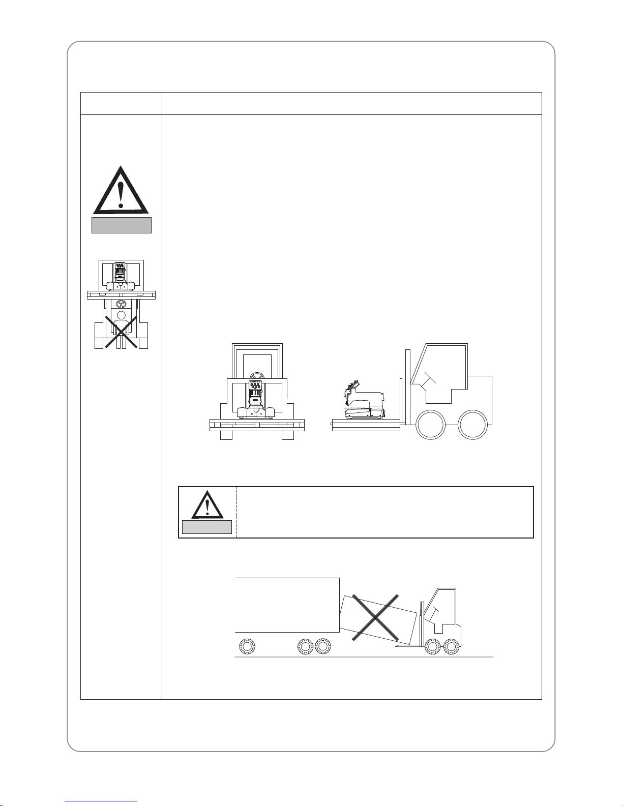
2.2.2) Delivery using a forklift
1) Make sure that size and weight of the forklift is sufficient to support the machine.
2) Place the machine so that its center is on the fork arm. Lift the machine carefully from
behind so that the machine does not tilt to either side.
When unloading the machine from forklift or crane, make sure to
maintain the weight balance in order to prevent injury or machine
damages.
WARNING
Make sure all
persons and
obstacles are out of
the way of the
moving machine.
Warning mark
Description
Page 9
9
2.3) MACHINE INSTALLA TION
CAUTION
2.3.1) Machine malfunctions or physical damages may occur due to
condition of the installation environment. Make sure to meet the
following conditions.
1) The foundation (floor) under the machine must be strong enough to support the
weight of the machine (approximately 3.5 tons).
2) Air conditioning can eliminate dust and humidity , which may cause pollution and
corrosion of the machine. Make sure your machine is regularly maintained.
3) Do not expose the machine to direct sunlight. (Long exposure to direct sunlight can
fade the machine paint or deform the machine shape.)
4) Allow at least 50cm space on each side of the machine (right, left, rear) from the wall
for convenient maintenance.
2.4) MACHINE OPERATION
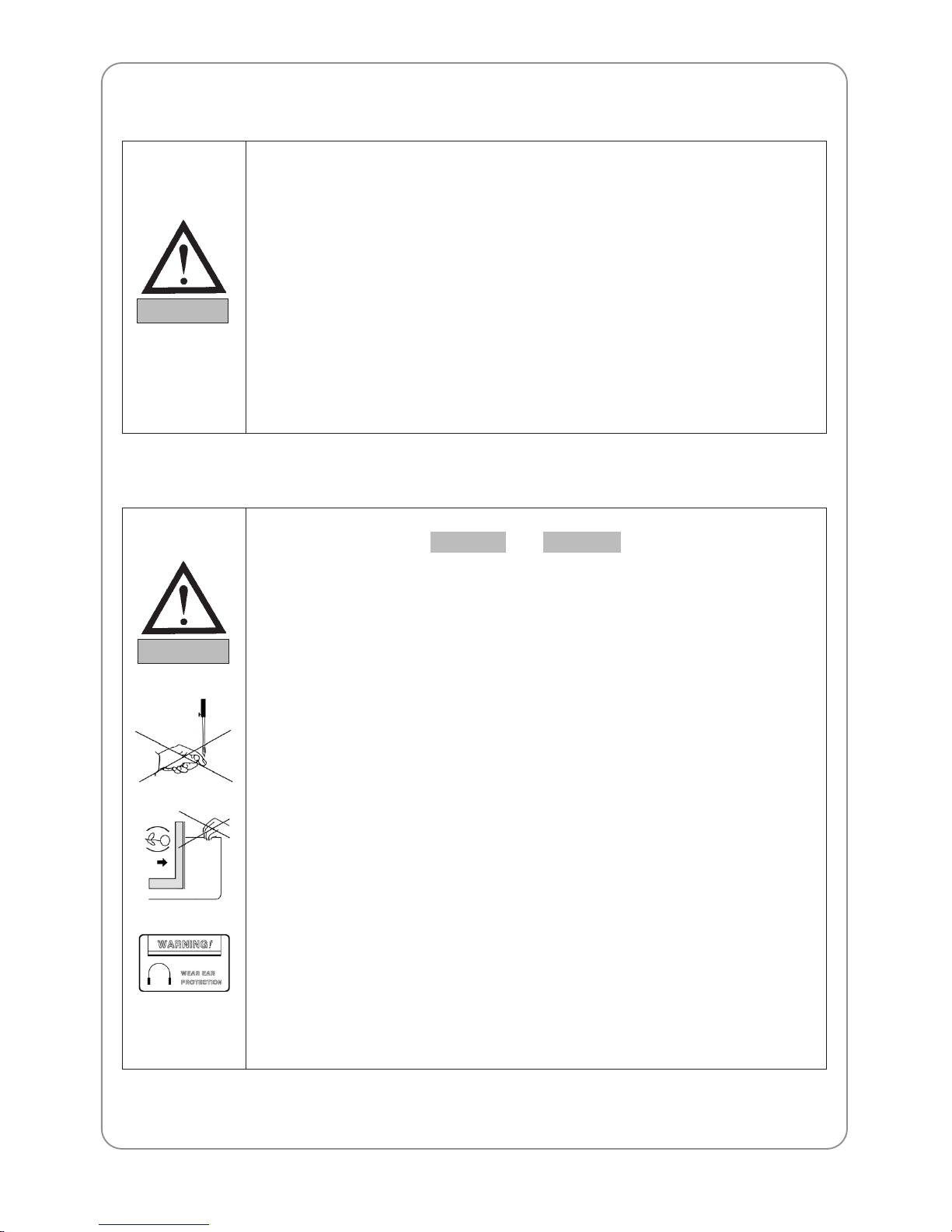
2.4.1) The machine has and labels on each risky
parts. Pay careful attention to the labels and make sure to observe
them during operation.
1) Read thoroughly and fully understand the manual before operating the machine.
2) Dress for safety . Long and unbound hair, jewelry such as necklaces, bracelets, and
wide sleeves can get caught in the machine. Wear shoes with non-slip soles to prevent
slip-off accidents.
3) Check the scope of machine operation to see if there is no problem.
4) Keep your hands or head away from the moving parts of the machine such as needle,
hook, take-up lever, and pulley when the machine is in operation.
5) Do not remove the safety covers on the pulley or shaft when the machine is in
operation for your safety .
6) Be sure the main power is turned off and the power switch is OFF before opening the
cover of any electrical components such as control box.
7) Be sure the main switch is OFF before manually turning the main shaft.
8) Turn OFF the machine when you thread needles or inspect the finished embroidery.
9) Do not lean against the cradle or place your fingers near the pantograph guide
grooves. You may hurt your fingers when the frame moves.
10) The machine noise may exceed 85db when it runs at the maximum speed.
WARNINGCAUTION
WARNING
Page 10
10
2.5) REPAIR
DANGER
2.5.1) Only SWF-trained and designated engineers should perform repair
work.
1) Turn OFF the power before cleaning or repair. W ait for 4 minutes so the machine
electricity is completely discharged.
2) Do not change the settings or any parts on the machine without consulting with SWF.
3) Use only official SWF parts when repairing your machine or replacing parts.
4) Re-install all safety covers when you are finished with the repair.
It takes approximately 10 minutes after turning off the main switch
before the electricity is fully discharged from main shafts and the
X/Y drive box.
CAUTION
Machine changes without consultation with SWF may cause risks
to your safety when you operate the machine.
DANGER
Page 11

PRODUCT FEATURES
03
11
3.1) EXP ANDED MEMORY
- It enables saving up to 200 designs in a memory; the maximum capacity of memory is 10 million needles.
3.2) MIRROR IMAGE CONVERSION
- You can turn the design from 0°to 359°by 1°and also mirror the design (reverse in the X direction).
3.3) ENLARGING AND REDUCING DESIGN
- You can reduce or enlarge the design from 50% to 200% by 1% along the X, Y axis.
3.4) AUTOMATIC SELECTION OF NEEDLE BAR
- You can select the order of the needle bars up to the 300th bar.
3.5) GENERAL REPETITION WORK
- The same design can be repeated up to 99 times along the X, Y axis.
3.6) SPECIAL REPETITION WORK
- It functions to continuously work by changing mirror and angle over a variety of designs.
3.7) AUTOMATIC OFFSET
- The frame automatically returns to the offset point when the embroidery is finished, making it easier for you
to switch the frames. You can select AUTOMATIC OFFSET at PARAMETER SELECT MODE to move
the frame automatically to the desired point, making it easier to do appliqués and to switch the frames.
3.8) RETURN TO START
- The frame can be moved back to the start point of the design during the embroidery .
3.9) NON-STITCHING
- The frame and the needle bar can move backward and forward by the units of 1, 100, 1000, and 10000
stitches and by color without stitching.
3.10) FRAME BACKWARD
- When the thread breaks or runs out of track, you can move the frame back to the starting point of the design
in the units of one to ten stitches.
3.11) AUT OMATIC TRIMMING DEVICE
- The automatic trimming device is performed according to the design and the machine set-up in order to
enhance work productivity and quality of the finished product.
3.12) THREAD TENSION CONTROL SYSTEM
Page 12

12
3.13) FUNCTION THA T HAS AN AUT OMATIC SENSOR OF CUTTING THREAD
- The machine detects when the upper thread breaks or the lower thread is out of the needle and automatically
stops the machine.
3.14) FRAME CENTER
3.15) AUTOMATIC RETURN TO STOP POINT IN UNEXPECTED BLACKOUT
- When the power fails unexpectedly , the frame moves back to the exact point where the stitching stopped.
This helps reduce the number of defects.
3.16) USB INPUT/OUTPUT
- It realizes an easy and simple way of input-output of DATA through the port for USB which is newly
applied. Input-output of DATA is possible while being connected with PC.
3.17) EDITING
- You can delete, change, or insert stitch data and function codes (jump, finish, trimming).
3.18) MULTI-LINGUISTIC SUPPORT
3.19) THE SCREEN WILL INDICA TE THE CAUSE OF ANY MACHINE ST OPS.
3.20) THE SCREEN INDICA TES RPM DATA.
3.21) FRAME MOVEMENT SPEED
- You can adjust the frame speed to high, medium, or low .
3.22) THE SCREEN INDICA TES THE MEMORY AVAILABLE FOR USE.
3.23) OTHER BRAND CODES
- The machine can automatically read designs of various formats stored in the floppy disk.
[ Readable Format ]
1. SST 2. DST
Page 13
MACHINE INSTALLATION AND PRECAUTIONS
04
13
4.1) INSTALLA TION CONDITION
4.1.1) T emperatures
1) When machine in operation: 15 ~ 40℃ (59 ~ 104℉)
2) When machine is idle: -25 ~ 55℃ (-13 ~ 131℉)
4.1.2) Humidity
1) relative humidity : 45~85%
4.1.3) Grounding
Ensure the electricity is properly grounded.
4.1.4) Surrounding environment
Close any doors or windows near the machine to prevent direct sunlight, dust, and humidity .
4.1.5) Place of installation
Foundation (floor) under the machine must be sufficiently strong and flat concrete to support the weight of the
machine.
4.1.6) Industrial environment classification
Installation and use of the machine must be performed in an industrial area.
(SWF machines should be used in Class A environment)
Meet the conditions described in the manual when installing the machine. Failure to follow the
directions may result in unexpected machine malfunctions.
CAUTION
1) Do not let moisture drops on the machine.
2) Provide air conditioning to control humidity and to prevent dust and corrosion.
CAUTION
Ensure properly grounding of the machine to avoid the possibility of electric shock. Use threewire grounding (grounding resistance below 100 ohms).
CAUTION
Page 14
14
4.2) ELECTRICITY INSTALLA TION ENVIRONMENT
4.2.1) Input voltage (to be adjusted at installation)
100V, 110V, 120V, 200V, 220V, 240V, 100V~240V free voltage
4.2.2) Allowed voltage range
Within 10% of the voltage set
4.2.3) Electric capacity and power consumption
3KVA 1.4~1.6KW
4.2.4) Insulation resistance
Over 10M ohms (measured with 500V insulation tester)
4.3) LEVELING THE MACHINE
4.3.1) Leveling the equipment
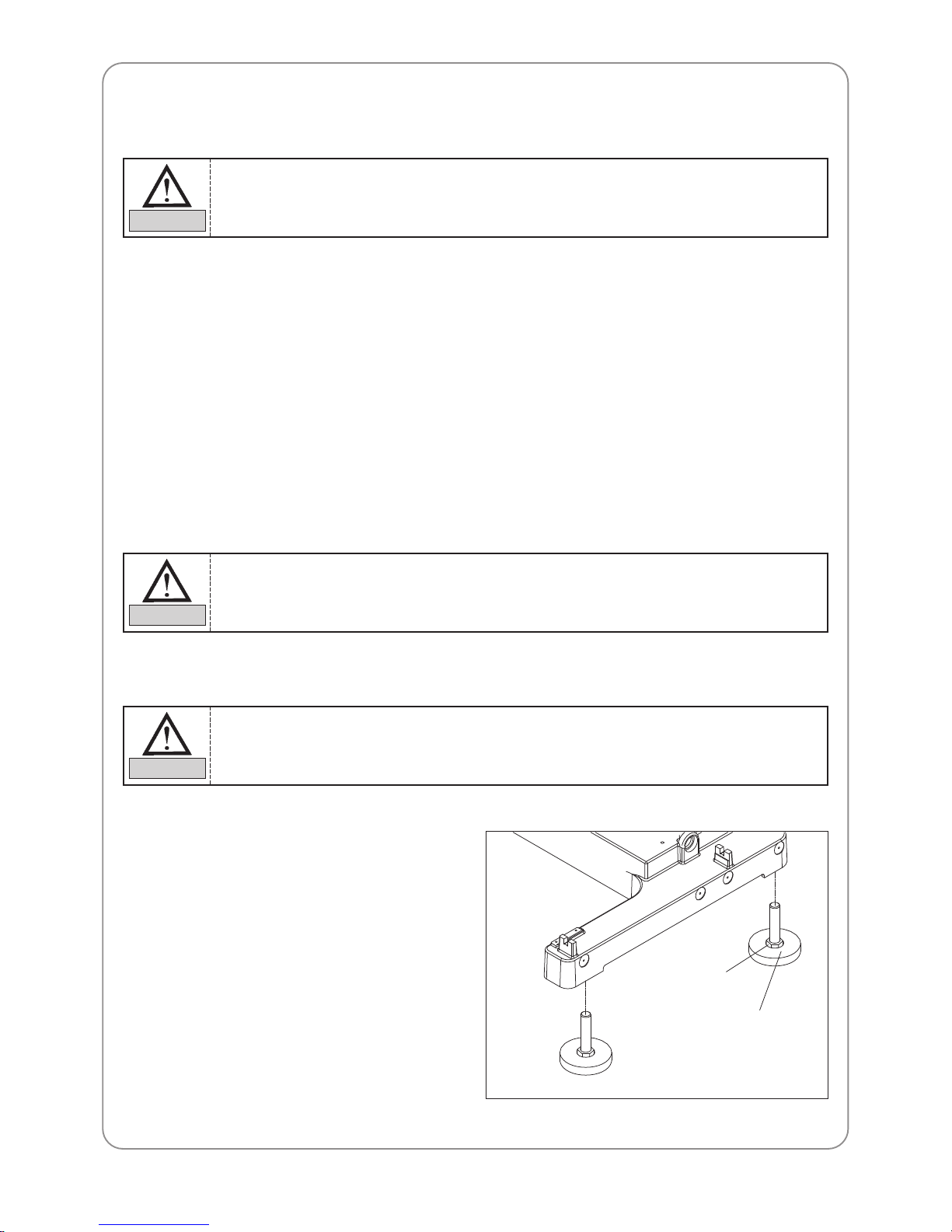
1) Stand
– If the stand is not installed
If the dedicated stand (optional) is not
attached, use the adjusting bolt to adjust the
back & front and left & right balance of the
machine.
Fixing nut
Adjusting bolts
Check if the input voltage of the machine corresponds with the voltage supply before installing
or operating the machine.
WARNING
1) Make sure to check the voltage supply where the machine will be installed.
2) Install the cable away from the operator
’’
s work space to prevent accident or injury.
WARNING
The machine must be accurately leveled (especially front-back) to prevent machine from
deformation or needle from moving out of position.
CAUTION
Page 15
15
– If the stand is installed
If the dedicated stand (optional) is attached,
reach it duly on the stand table.
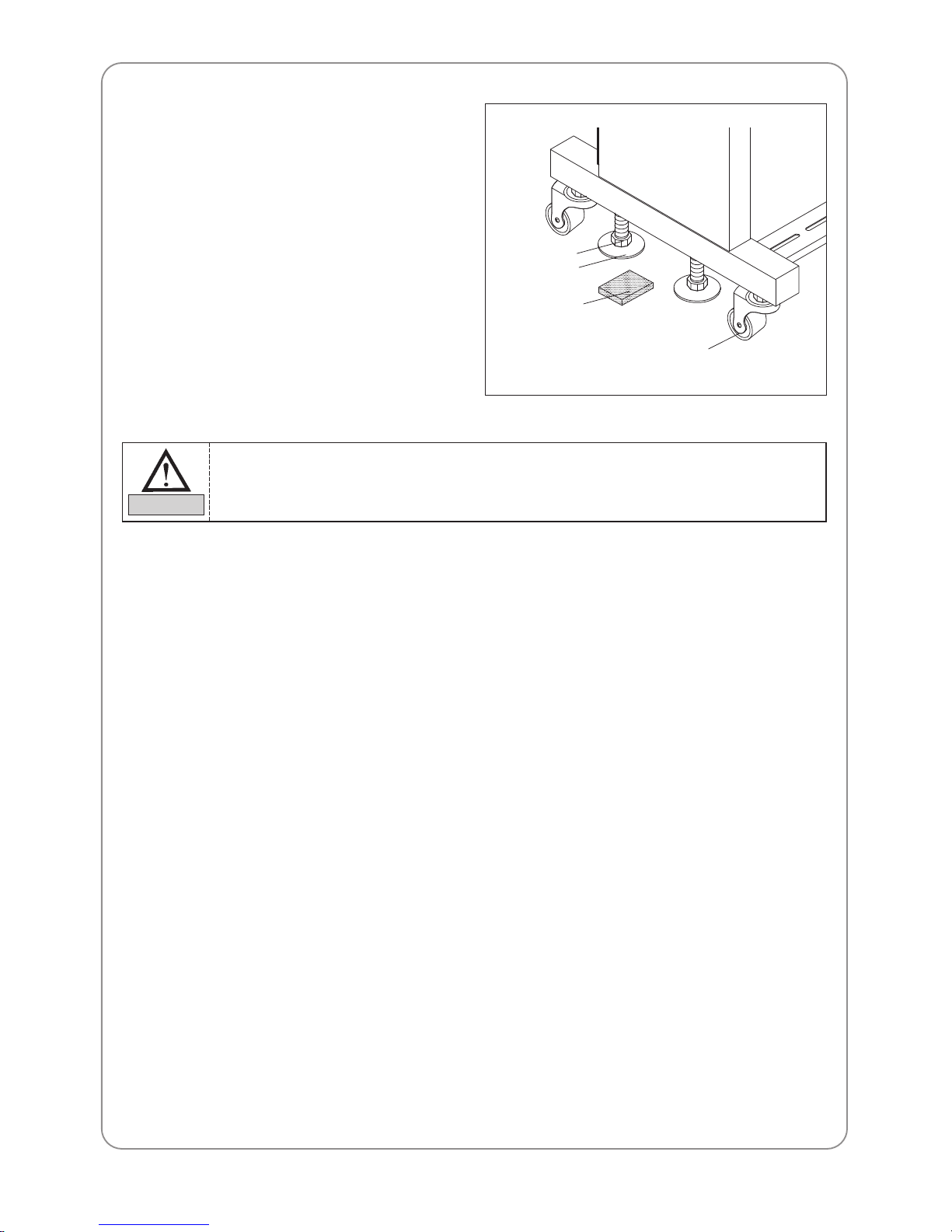
2) Vibration-proof rubber
Place the vibration-proof rubbers (four)
under each leveling adjusting bolts. Adjust
the bolts until the caster rises from the floor.
Use the level gauge to check the leveling.
Caster
Fixing nut
Leveling
adjusting bolt
Vibration-proof
rubber
1) Check the voltage supply where the machine will be installed.
2) If the difference in heights of the four bolts is over 10mm, place spacers beneath the lower
level base to make the heights even.
CAUTION
Page 16
MACHINE USE AND PRECAUTIONS
05
16
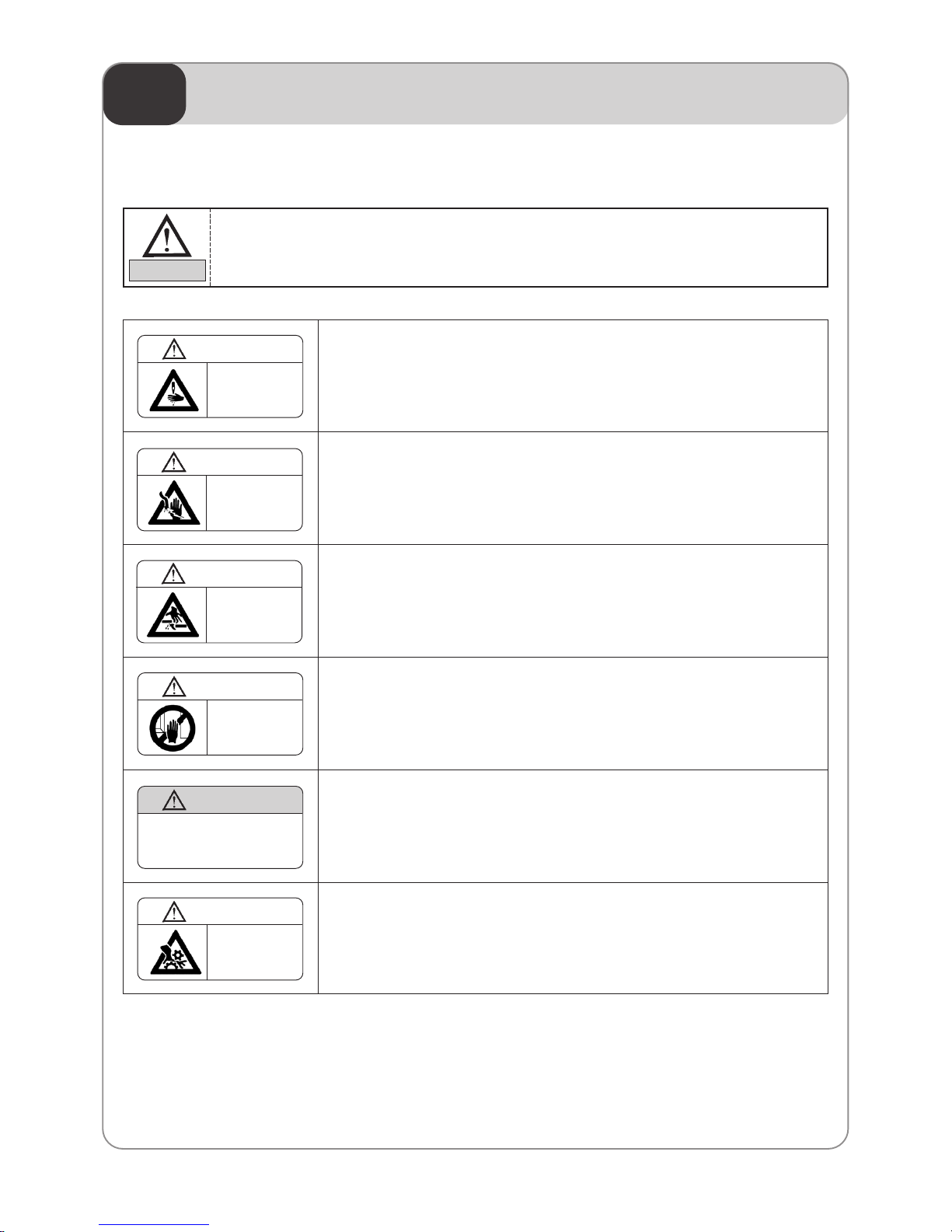
5.1) TYPES OF SAFETY LABELS
※※
NEEDLE
Injury may be caused by moving needle.
Ensure that the machine is in a stop condition before changing, threading
or rethreading of needies or changing of needles.
※※
HIGH VOLTAGE
Fire or death may be caused by high voltage electric shock.
Don’t open the cover except for service man assigned by SWF.
When open the cover turn off power and wait for 6 minutes.
※※
CRACK
Physical injury may be caused by crevice.
Don’’t put your finger in a groove on the table.
※※
HAND
Physical damage may be caused by interposition.
While embroidery frame is running according to the direction of
embroidery frame may be injured your hands by gap between fixed body
and embroidery frame.
※※
MACHINE MOVE
Physical damage may be caused by winding.
Don’t put your hands near the arrow while the main shaft is rotating
※※
MACHINE MOVE
Injury may be caused by winding.
Be sure to turn off the power before cleaning, lubricating, adjusting or
repairing.
Observe the directions on the safety labels for your safety.
CAUTION
Injury may be caused by moving
needle.
Ensure that the machine is in a
stop condition before changing,
threading or rethreading of
needies or changing of needles.
WARNING
WARNING
Fire or death may be caused by
high voltage electric shock.
Don’t open the cover except for
service man assigned by SWF.
When open the cover turn off
power and wait for 6 minutes.
WARNING
Physical injury may be caused
by crevice.
Don’t put your finger in a groove
on the table.
Physical damage may be caused
by interposition.
While embroidery frame is running
according to the direction of
embroidery frame may be injured
your hands by gap between fixed
body and embroidery frame.
WARNING
Injury may be caused by winding.
Be sure to turn off the power
before cleaning, lubricating,
adjusting or repairing.
WARNING
Physical damage may be caused by
winding.
Don’t put your hands near the
needle bar & take-up lever while
machine is running.
WARNING
Page 17
17
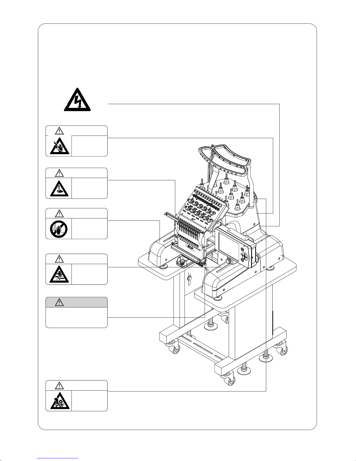
5.2) LOCATIONS OF SAFETY LABELS
WARNING
Fire or death may be caused by
high voltage electric shock.
Don’t open the cover except for
service man assigned by SWF.
When open the cover turn off
power and wait for 6 minutes.
Injury may be caused by moving
needle.
Ensure that the machine is in a
stop condition before changing,
threading or rethreading of
needies or changing of needles.
WARNING
Physical damage may be caused
by interposition.
While embroidery frame is running
according to the direction of
embroidery frame may be injured
your hands by gap between fixed
body and embroidery frame.
WARNING
WARNING
Physical injury may be caused
by crevice.
Don’t put your finger in a groove
on the table.
Injury may be caused by winding.
Be sure to turn off the power
before cleaning, lubricating,
adjusting or repairing.
WARNING
Physical damage may be caused by
winding.
Don’t put your hands near the
needle bar & take-up lever while
machine is running.
WARNING
Page 18
NAMES OF MACHINE PARTS
06
18
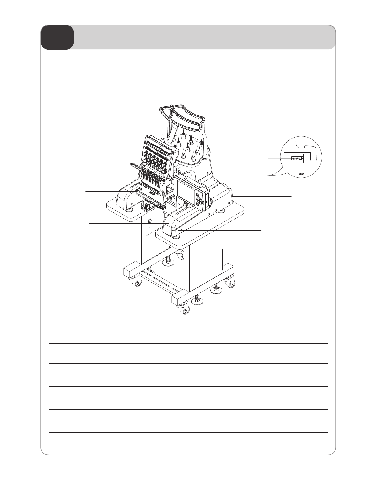
① Machine Body
② Table
③ Thread stand
④ Main shaft drive motor
⑤ Bed
⑥ Trimming drive box
⑦ Arm
⑧ Color change box
⑨ Upper thread holder
⑩ Head
⑪
Thread tension adjustment board
⑫ X-axis driving system
⑬ Y-axis driving system
⑭ Controller box
⑮ Operation box
⒃ Encoder
⒔ Main power switch
⒕ Leveling adjusting bolt
⒖ Lamp
③
⑦
⑪
⑩
⒖
⑨
⑤
⑥
⒕
⑬
②
⑫
⑮
①
⑧
⒃
⒔
⑭
④
Page 19
PERIPHERALS ASSEMBLY
07
19
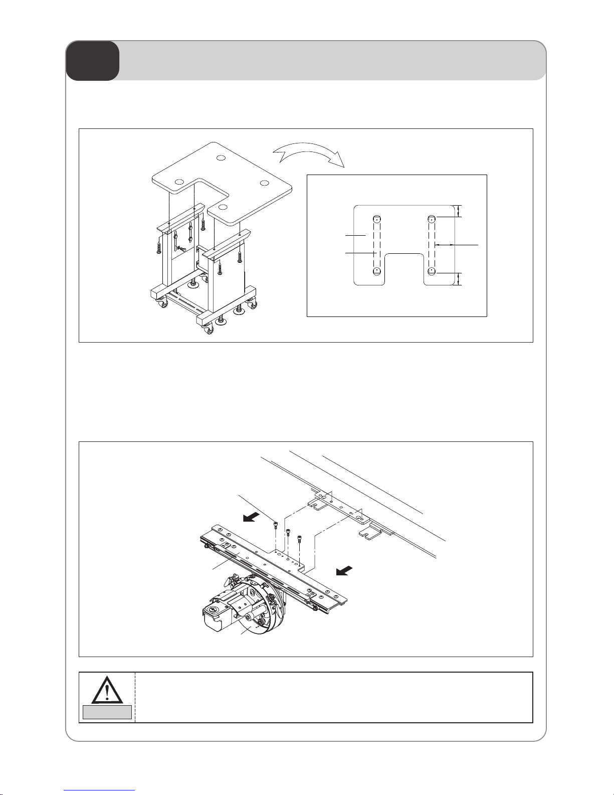
7.1) STAND ASSEMBLY (Optional)
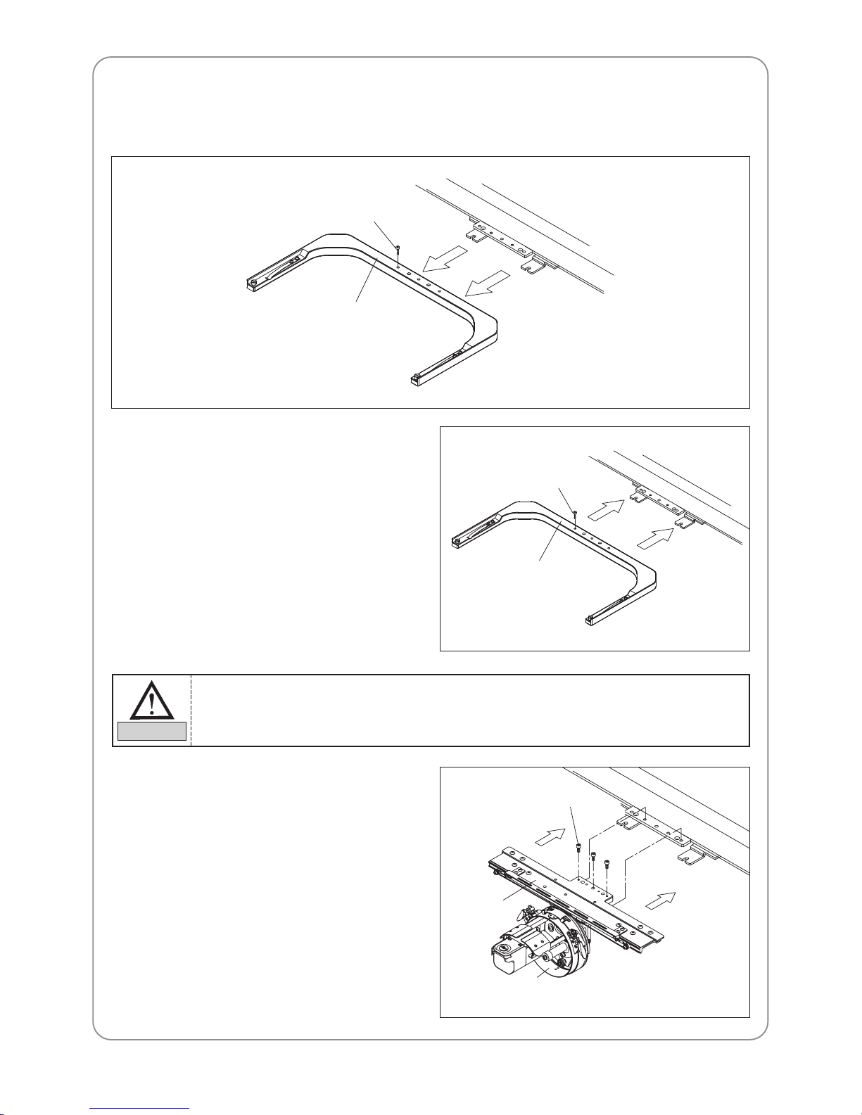
7.2) CHANGE CAP TO TUBULAR
7.2.1) Disassembling the cap frame driving set
Unscrew the fixing bolts to disassemble the cap frame driving set from the frame connection plate.
Fixing bolts (Three)
Frame connection plate
Cap frame unit
Driver ring
You will need the fixing bolts when installing the tubular plate. Keep them safe.
CAUTION
▷
Place the table on the stable in the stable manner and fasten tightening screws.
Stand Table
Stand
171.5mm
105.5mm
99.5mm
Page 20
20
7.2.2) Assembling tubular frame plate
Use the fixing bolts to fix the tubular frame tightly to the frame connecting plate.
Fixing bolts
Tubular plate
Frame connecting plate
7.2.3) Changing tubular to cap
1) Disassembling the tubular plate
Unscrew the fixing bolts to separate the tubular
plate from the frame connecting plate.
2) Assembling the cap driving set
Use the fixing bolts to fix the cap driving set
tightly to the frame connecting plate.
Fixing bolts
Fixing bolts
Frame
connecting
plate
Driver ring
Cap frame
unit
Tubular plate
Frame connecting
plate
You will need the fixing bolts when installing the cap driving set. Keep them safe.
CAUTION
Page 21
BASIC FUNCTIONS FOR MACHINE OPERATION
08
21
8.1) BASIC OPERATION
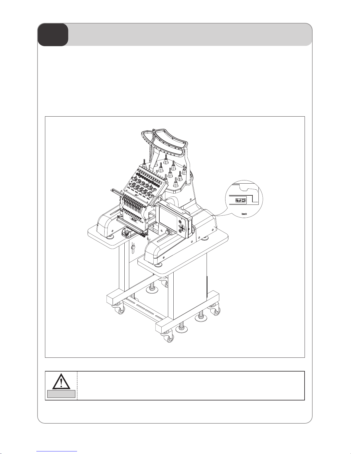
8.1.1) Power
1) Plug in the power of the embroidery machine.
2) Turn on the power switch.
3) OP Box's LCD screen is turned on, and the operating program starts running.
Make sure to plug OFF the power when inspecting the machine.
CAUTION
Page 22
22
8.1.2) For starting embroidery and stopping the machine
You can use START and ST OP switches during machine operation in the following cases.
1) For starting or stopping the embroidery work
2) For moving the frame backward during embroidery work stop
Switch Machine Operation
Press START Machine starts and embroidery work begins.
Hold START Machine “inching (see Note1)”until you release the START switch.
Press STOP Machine stops.
Switch Machine Operation
Press STOP Frame moves backward in selected frame movement units (see Note 2)
Hold STOP Frame starts to move backward.
If you release STOP before the machine goes 10 of the selected
stitches, the machine will stop immediately (the machine moves in the
selected frame movement units). If you release the switch after the
machine traveled 10 of the selected stitches, the machine will continue
to move back.
Press STOP Press STOP again and the machine will stop moving backward.
1) Non-stitching (floating) function is not available in the initial menu.
2) To perform floating at the start of embroidery, press STOP switch. The machine will then go
into STOP MODE. Select FLOAT and set the number of non-stitching desired in the sub
menu.
NOTE
3) For backward non-stitching during embroidery work stop
Same as START/ST OP during embroidery work stop
1) “Inching” refers to low-speed embroidery at 100 rpm range, performed for stable stitching
when the machine is re-started after stop.
2) “Frame movement unit” refers to the “13. BK STITCH UNIT” in “Parameter Set-Up”. You can
select from 1 to 10 stitches (by 1 stitch).
NOTE
Page 23
23
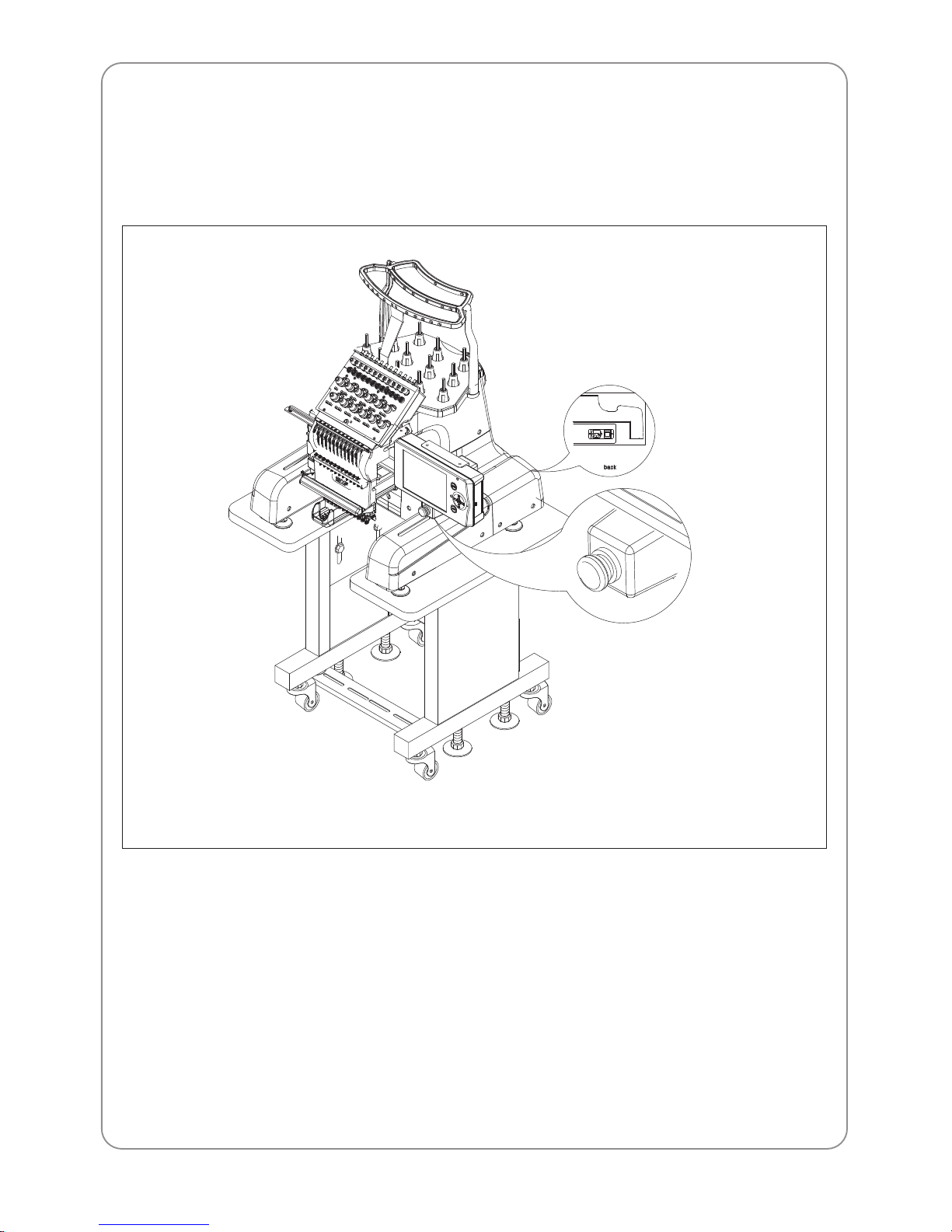
8.1.3) EMERGENCY STOP
Press EMERGENCY STOP if you have to stop the machine urgently due to unstable machine operation.
1) Press EMERGENCY STOP and the machine will stop immediately.
2) Turn OFF the EMERGENCY STOP after addressing the risk factors or problems.
Page 24
24
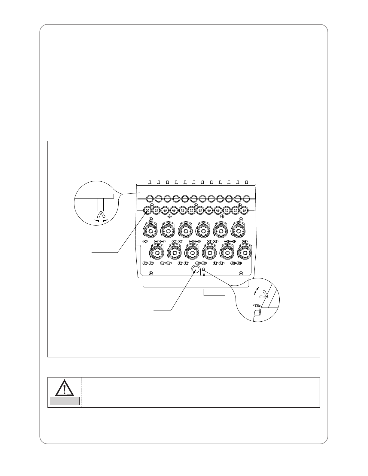
8.1.4) LAMP SWITCH ON THREAD TENSION ADJUSTMENT BOARD
1) Switch
– For normal operation, turn the toggle switch on to turn on the indicator lamp.
– If the machine stopped after detecting a thread break, move the frame back to the location of the thread
break and restart the machine to pick up stitching (design edit).
– T o set the needle bar so a specific head does not work, turn the toggle switch of f.
2) Thread break detector lamp
Lamp on the thread tension adjustment board will blink if upper and lower thread break is detected,
regardless of the toggle switch status.
ON
OFF
Thread break
detection switch
Lamp
Toggle switch
Thread detection roller
ON
OFF
Interference to the thread detector roller (due to foreign substances around the thread detector
roller, etc.) can cause the thread break lamp to blink.
CAUTION
Page 25
25
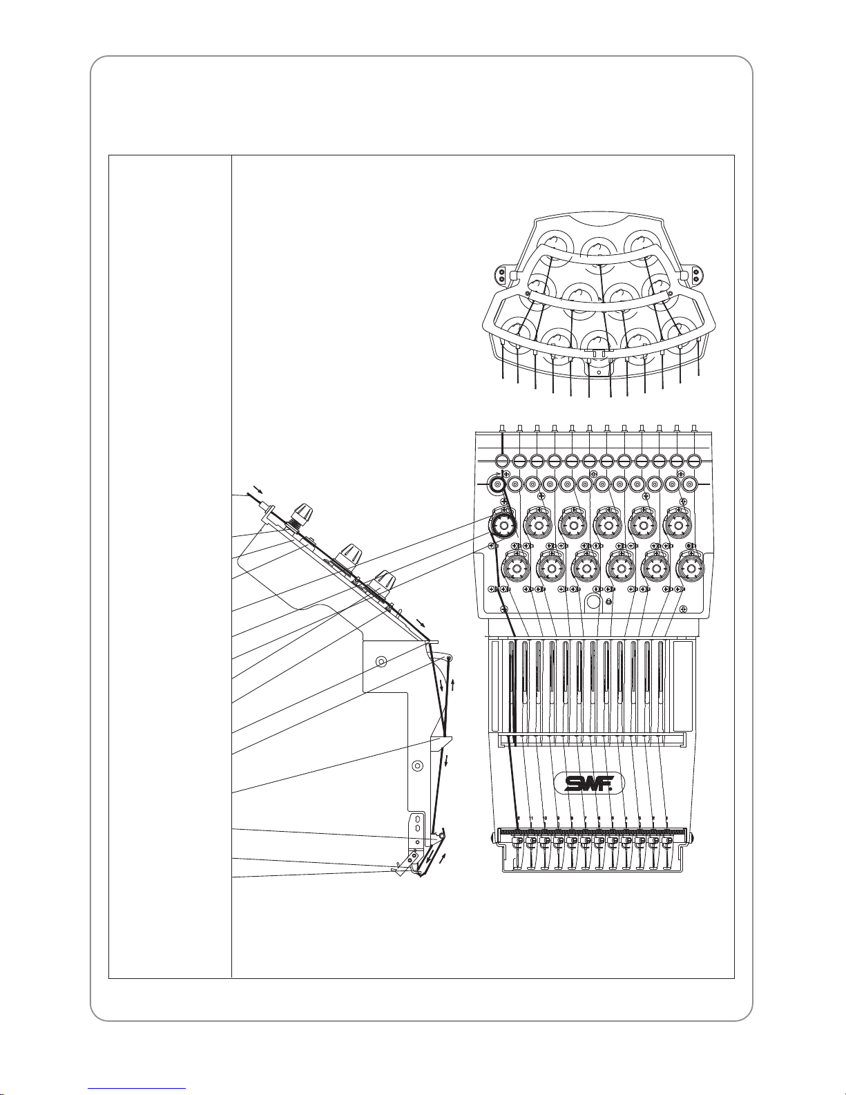
8.1.5) Upper threading and tension adjustment
1) Upper threading
Upper thread stand
Upper thread
(from the upper
thread stand)
Sub thread adjuster
Thread tension
adjustment board
Thread detecting roller
Take-up lever spring
stopper
Take-up spring
Rotary tension disk
Main thread tension
adjuster
Upper thread guide
Thread guide (upper)
Take-up lever
Thread guide (middle)
Upper thread holder
Presser foot
Needle
12
12
11
11
10
10
998
8
77665
5
443
3
2
2
1
1
Page 26
26
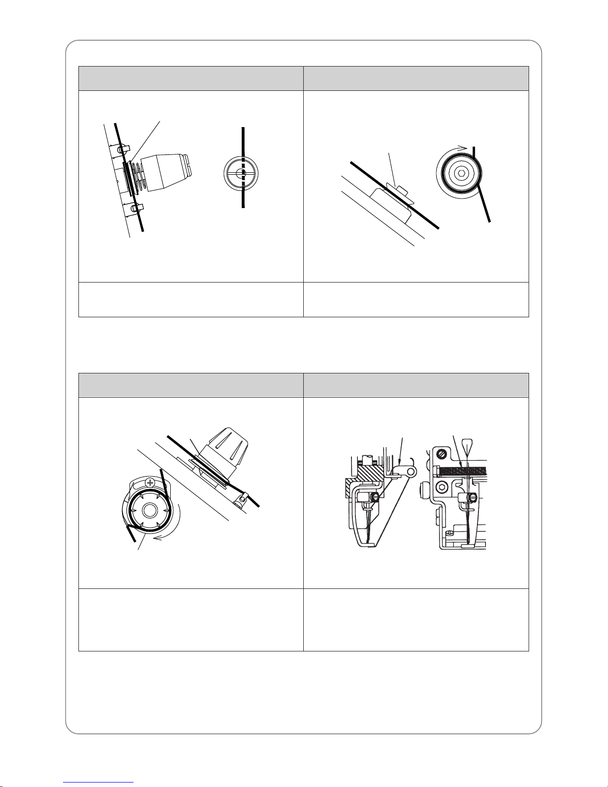
Threading the sub thread adjuster
Thread between the thread guide disk and through the
hole on the axis of the thread adjuster.
Wrap the thread around the V-shaped groove around the
detector roller (1 time).
Threading the thread detector roller
Thread guide disk
(penetrates the
center of the axis)
Thread detector roller
1-round
rotation
Threading the main thread tension adjuster
Wrap the thread 1.5 times around the rotary tension disk
(V-shaped groove.)
Let the thread pass the islet hole of the thread guide
(lower). Thread the needle holder thread guide and the
needle. Fix the upper thread in the upper thread holder
spring of the thread guide (lower).
Threading around the needle
Rotary tension disk
1.5-round rotation
Thread guide(lower)
Upper thread
holder spring
Page 27
27
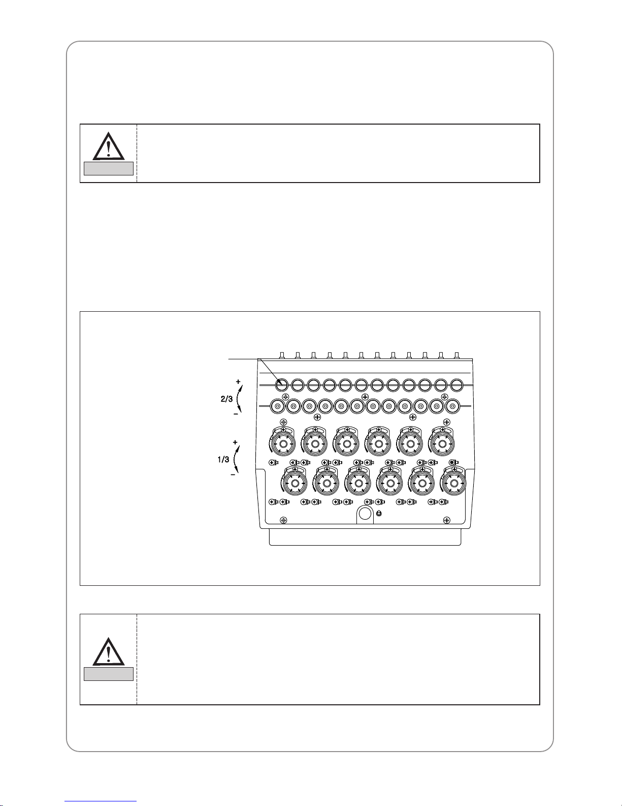
2) Upper Thread T ension Adjustment
Thread tension adjustment is critical for producing high quality of the embroidery . A balance of 2/3 upper
thread and 1/3 lower thread generally indicates good tension.
– The upper thread tension is controlled by sub and main thread tension adjusters. Turn adjusting nut
clockwise to increase the tension and counterclockwise to decrease the tension.
– The sub thread adjuster should control about 2/3 of the upper thread tension.
– The main tension adjuster should handle the other 1/3.
– Set the tension of the sub thread adjuster so the upper thread flows smoothly through the rotary tension
disks and into the rollers of the main tension adjuster.
Adjusting nut
Sub thread
adjuster
Main tension
adjuster
1) If tension is too weak
The upper thread will loop, causing thread tangles or breaks.
2) If tension is too strong
Puckering may occur as well as thread and needle breaks.
CAUTION
1) If tension at the sub thread tension adjuster is too loose, the detector roller may not rotate
well and make wrong detections.
2) After adjusting the tension, check if the upper thread tension is what can be pulled with little
force of around 100-120g.
3) After adjusting the tension, pull the upper thread to see if the detector roller rotates well.
4) Adjust the tension constantly according to the type of thread and fabric used.
CAUTION
Page 28
28
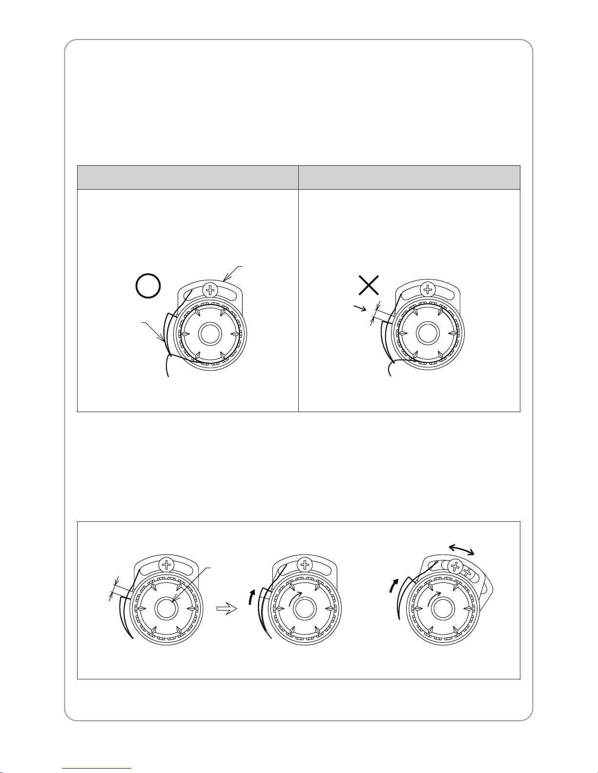
3) T ake-up spring adjustment
– Functions
Difference in the length of the upper thread pulled by the take-up lever and by the hook creates tension or
looping. The take-up spring absorbs the leftover of the upper thread. Increase the tension or the stroke of
the spring to form tight stitches on the embroidery .
– Adjusting tension of the take-up spring
You can adjust the tension of the take-up spring with its shaft. You can increase the spring tension by
turning it clockwise, and decrease the tension by turning it counterclockwise.
– T o adjust the stroke of the take-up spring
You can adjust the stroke of the spring by moving the take-up stopper to right or left.
○○
Correct position of the take-up spring
The take-up spring stopper touches the spring
Gap between the take-up spring stopper and the spring
(due to dust or foreign substances in the stopper)
××
Incorrect position of the take-up spring
Take-up spring
Thread
detecting
plate
Thread adjusting
shaft
Page 29
29
8.1.6) LOWER THREADING AND TENSION
ADJUSTMENT
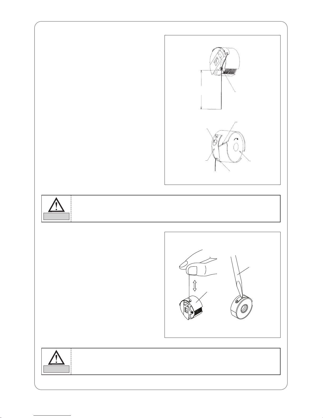
1) Lower threading
– Use cotton yarn (#80-#120) for your lower
thread.
–
Lower threading into the bobbin case
Insert the bobbin into the bobbin case with
the thread coming out from the case slot.
Pull the thread through the thread guide.
– T o prevent lower thread tangles, trim the
thread, leaving the length at 3-4cm, before
inserting the bobbin into the hook.
2) Lower thread tension adjustment
Adjust the tension of the lower thread using the
bolt on the tension spring of the bobbin case.
Turn the bolt clockwise to increase the tension
and counterclockwise to decrease the tension.
3~4cm
Lower threading
Slot
Bobbin
Fixing bolts
Tension spring
Thread guide
Bobbin case
driver
Make sure the bobbin rotates clockwise when you pull the thread holding the bobbin case in
your left hand.
CAUTION
To check if the lower thread tension is adequate, hold the thread from the bobbin and jiggle the
bobbin case lightly up and down. The thread should come out from its own weight and the
tension should be 25-35g.
CAUTION
Page 30
30
8.1.7) BOBBIN WINDER
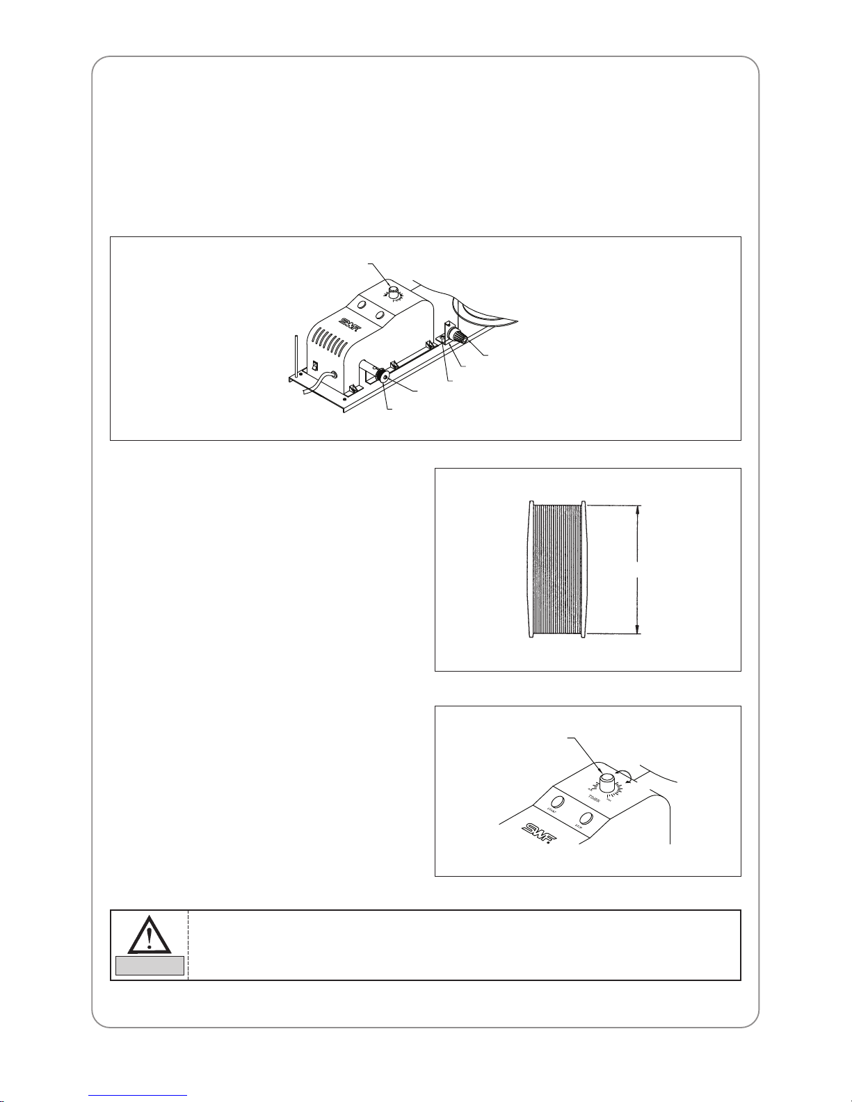
1) Bobbin winding
– Insert the bobbin into the thread winder shaft as in the figure below and manually wind the thread 5 to 6
times on the bobbin in the direction of winding the thread. Then press the start button.
– When the thread winding condition is poor, press the stop button. It will immediately stop the winding
shaft.
min
TIMER
START
STOP
max
2) Adjusting thread volume on the bobbin
– Fill the bobbin 80% and make sure the
thread is parallel to the bobbin as shown in
the figure.
80%
– The thread volume on the bobbin can be
adjusted by using the thread winding knob.
When the knob is turned clockwise, the
thread volume increases. When the knob is
turned counterclockwise, the thread volume
decreases.
1) Overfilling the bobbin may interfere with the smooth pull of the lower thread.
2) For normal bobbin, 80% fill will render around 80m of lower thread.
CAUTION
Knob
Bobbin axis
Bobbin
Thread tension adjustment screw
Tightening screw for the tension adjusting holder
Tension adjusting holder
Decrease
Increase
Knob
Page 31
31
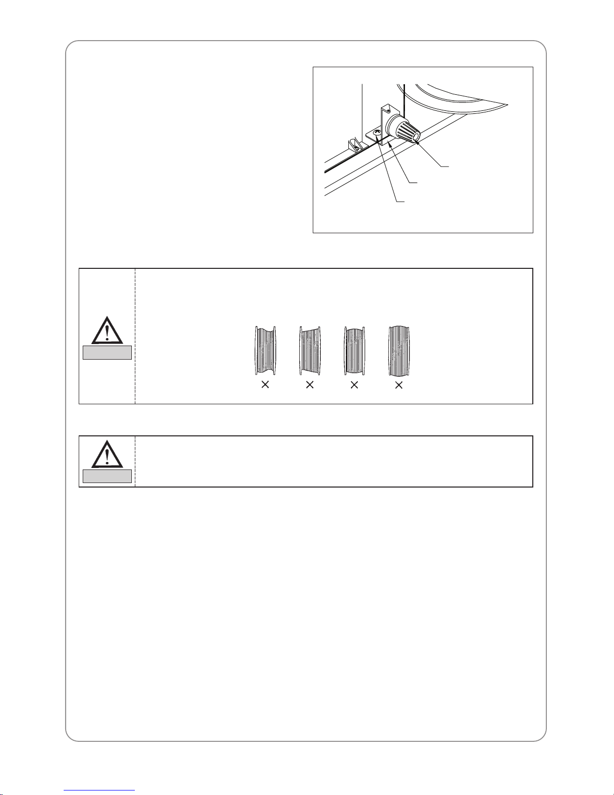
3) Adjusting the bobbin winding condition
– The thread should be wound around the
bobbin in parallel. Otherwise, loosen the
tightening screw for the thread winder's
tension adjusting holder and move the thread
guide body left or right for adjustment.
– Adjust the tension of the bobbin winding
using the tension adjusting nut.
Winding the bobbin off-center or uneven as shown below can cause thread breaks, skipped
stitches, or thread tangles.
CAUTION
Too tight tension of the bobbin winding can block smooth pulling of the thread and cause
thread breaks or short tails.
CAUTION
Tension adjusting holder
Tightening screw for the
tension adjusting holder
Thread tension
adjustment screw
Page 32
32
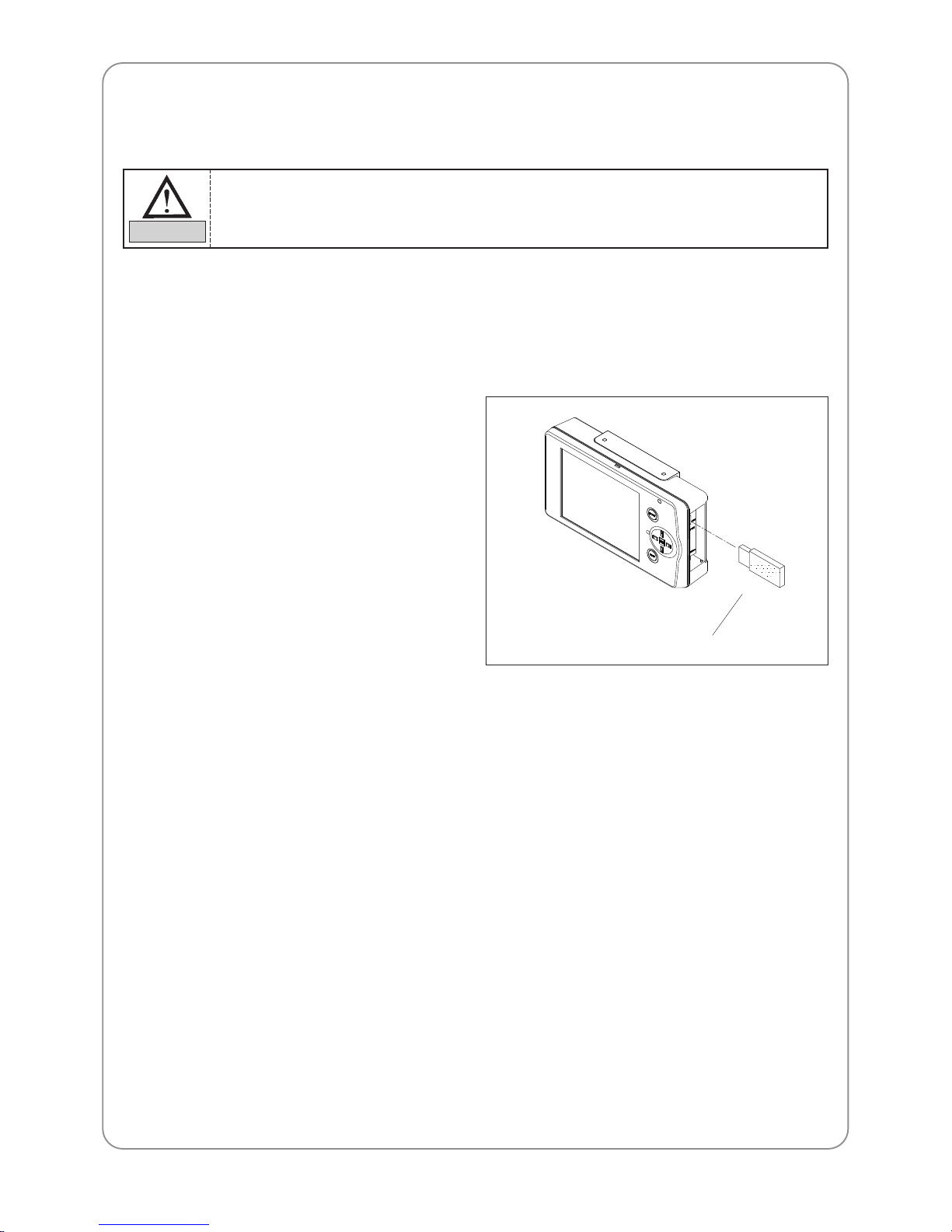
8.1.8) Notes when using USB memory sticks.
Make sure to meet the following conditions when using the above devices.
▶ When using USB memory sticks
– Do not delete USB memory from the USB port when reading and writing with USB.
8.1.10) How to take out USB memory sticks
– For USB, close the input/output window and delete the USB memory .
8.1.11) Reading and writing of embroidery designs
Serial USB memory communication is adopted in order to input the embroidery design in an op box through
an external device.
8.1.9) How to insert USB memory sticks
– Inserting USB memory sticks
Insert the USB memory into the USB port.
You can use USB memory sticks of FAT 16 (file system). The machine does not accommodate
FAT 32.
CAUTION
USB memory
Page 33
33
8.1.12) Return to stop position in unexpected blackouts
Your SWF embroidery machine automatically returns to the previous position when the power comes back on
after an unexpected blackout, thereby not affecting the quality of the embroidery.
(See LCD Monitor User Manual)
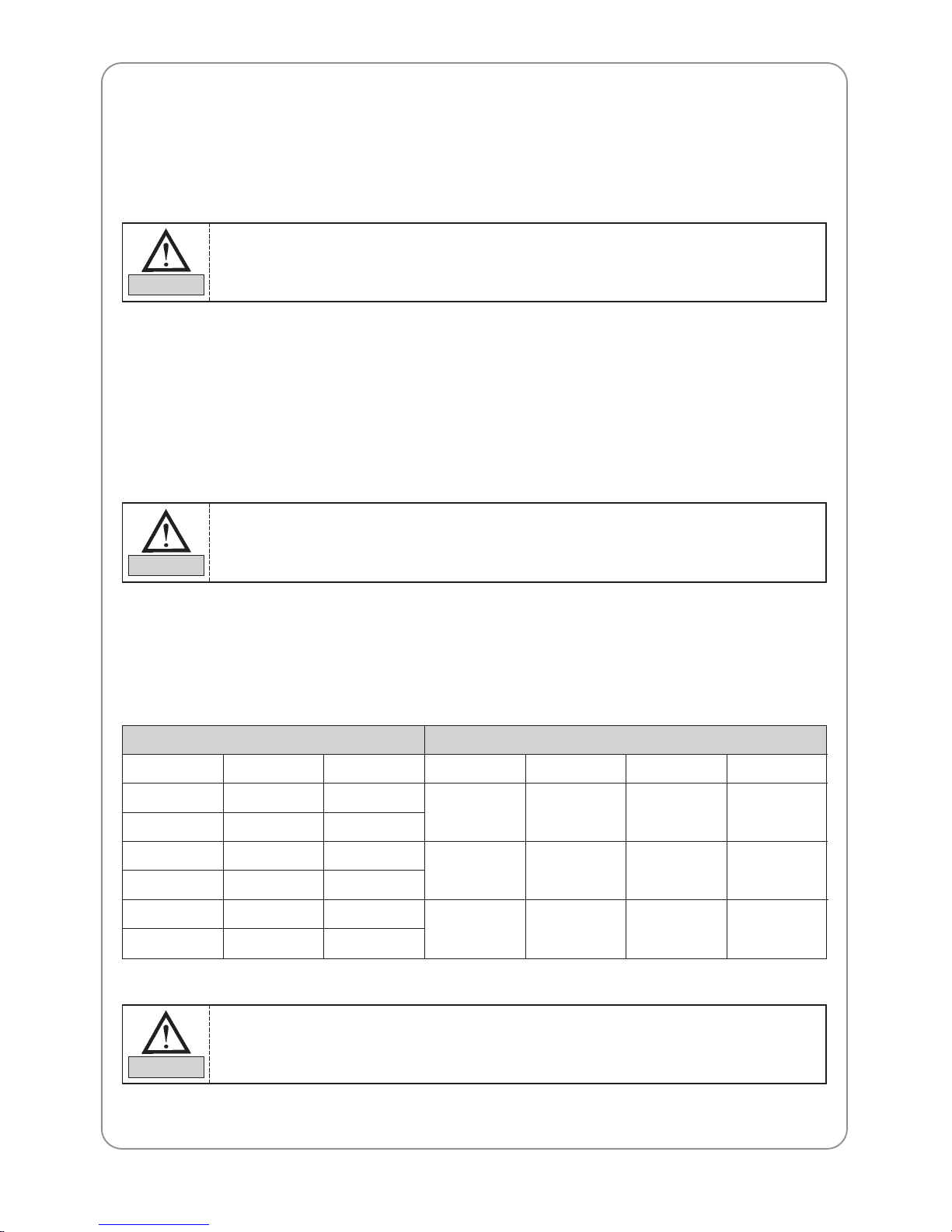
8.2) NEEDLE-HOOK TIMING AND RELATED TIPS
8.2.1) Needle
– It is very important to select the right needle for the type of thread and fabric used.
– Inappropriate needles can cause bad embroidery , thread breaks, skipped stitches, etc.
– For normal embroidery , use a DB×K5 needle.
8.2.2) Relationship between needle and thread
– Inadequate selection of threads and needles can result in thread breaks, skipped stitches, as well as in bad-
quality embroidery .
– Refer to the following table for threads and needles used in normal embroidery .
US
0.25
0.27
0.29
0.32
0.34
0.36
Japan
9
10
11
12
13
14
Germany
65
70
75
80
85
90
Cotton #
70~80
50~60
36~40
Silk
100~120
80~100
60~70
Nylon
130~150
100~130
80~100
Rayon
70~100
100~130
130~150
Needle Size Thread Size
Make sure to turn OFF the main switch in unexpected blackouts until the power comes back
on.
CAUTION
DB××K5 needle has an eye twice larger than that of DB1 (used for normal stitching).
Use DB××K5 for normal embroidery.
CAUTION
Needle and thread most commonly used in embroidery
Thread : rayon yarn 120d/2.
Needle : DB××K5 #11
NOTE
Page 34
34
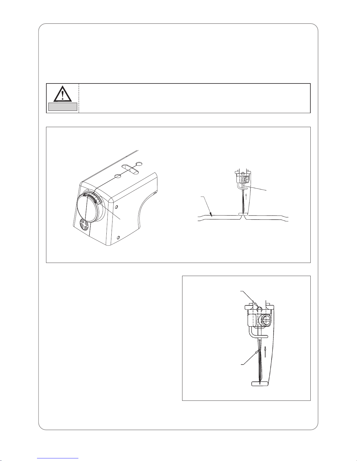
8.2.3) Changing the needle
– Make sure the needle is completely clear of the needle plate before changing it. If the needle is not clear of
the plate, use the main shaft handle, manually turn the main shaft to put the needle in the right location for
change.
– When inserting the needle, make sure that the
groove of the needle is facing front.
– End tip of the needle should be inserted
completely into the needle bar.
Hole for inserting
needle
Slit on the front
of the needle
1) Turn OFF the machine according to the safety rules before turning the main shaft manually.
2) Immediately remove the main shaft handle afterward: it is dangerous to operate the machine
with the handle inserted.
CAUTION
Needle plate
Needle
Hand pulley
Page 35
35
– When using special threads, such as artificial
silk, you might want to turn the groove of the
needle to the right in order to minimize the
thread breaks.
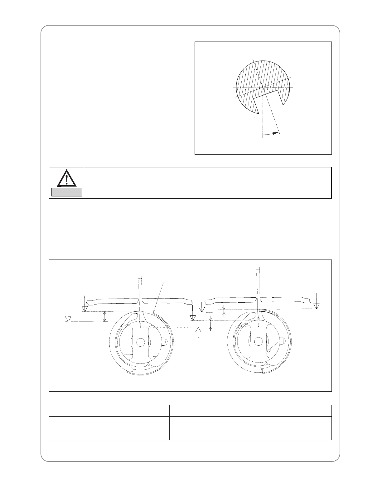
8.2.4) Relationship between needle and hook
– Adjusting timing between needle and hook
Default timing of the needle and the hook is set by the main shaft angle of 201°. Relationship between the
needle and the hook varies as below .
Top edge of the
needle hole
Top point of hook
circumference
a
Hook point
Top edge of the
needle hole
Needle tip
Lower dead stop
of the needle bar
Hook point
b
c
a. At lower dead stop of the needle bar 2.3~3.7 mm
b. At needle-hook timing 1.8~2.2 mm
c. At needle-hook timing 0.5~1.5 mm
If the needle is not inserted all the way to the top of the needle bar hole, timing of the machine
will go off, causing broken needles and thread breaks.
CAUTION
Page 36
36
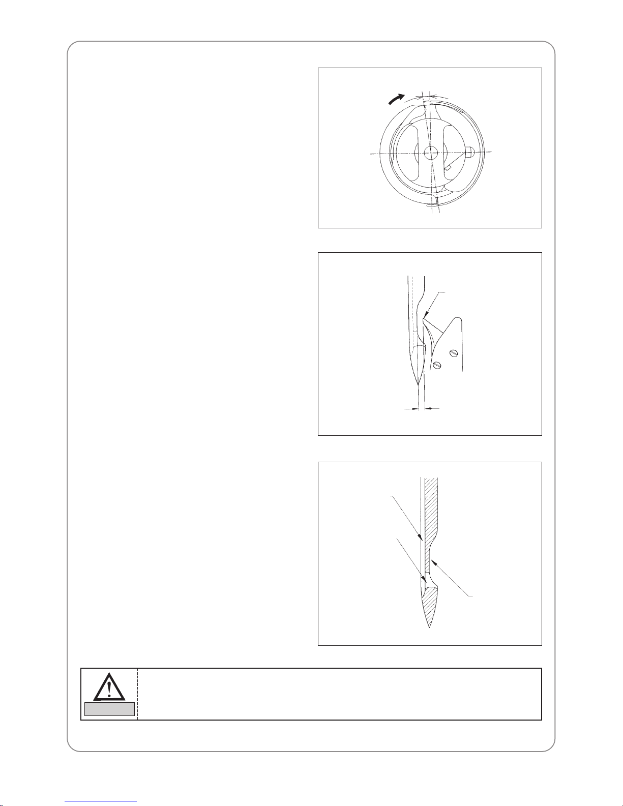
– Adjusting allowance in the hook
The hook can move right and left if there is an
allowance in the lower shaft gear. Eliminate the
allowance (gap) by turning the hook clockwise.
Then adjust the timing.
8.2.5) Adjusting gap between needle and
hook point
– Gap between the hook point and the needle
The distance between the needle and the hook
should be 0.1-0.3mm at their closest interface.
– Thread skip
Thread skip occurs due to thread looping or
inadequate balance or gap between the needle
and the hook.
– Adjustment
The closer the hook point is to the needle, the
hook point will be inside the loop and threading
will be more stable.
Hook allowance (gap)
Hook point
0.1~0.3mm
8.2.6) Functions by needle shape
Hole and groove of the needle vary by the size
and type of the needle.
– Front groove
It protects the thread from the friction heat of
the sewing (which can cause thread breaks).
– Back groove
It adjusts the hook timing according to the
needle movement, thus preventing thread
skips.
Back groove
Front groove
Needle eye
1) Prevention of looping is important for stitching. Adjust the hook point as close to the needle
as possible to achieve the perfect thread position.
2) If embroidery state is not good, move the needle slightly to the right.
CAUTION
Page 37
37
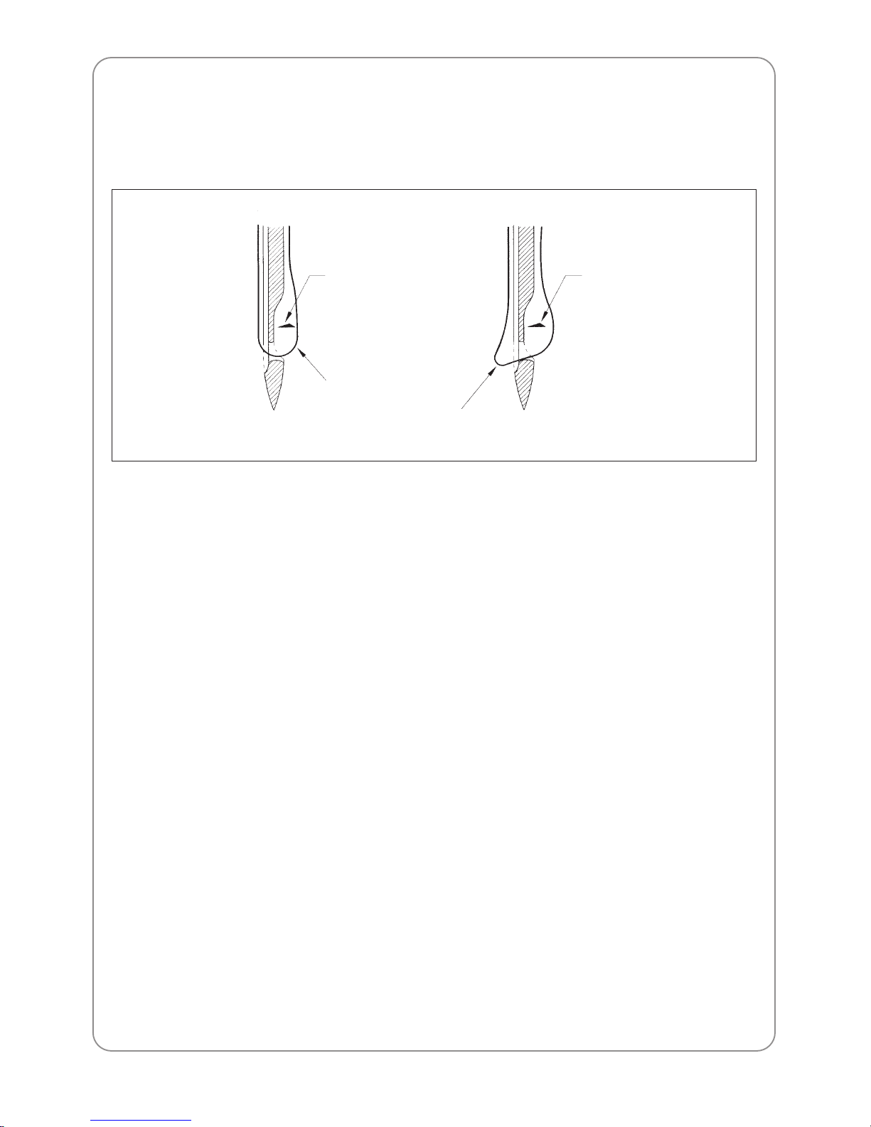
8.2.7) Different loop shapes
Shape of the loop varies by the type of thread or fabric. Unstable shape of the loop may result in skipped
stitches. The following pictures show different shapes of loop formed by different types of thread.
Hook point
Hook point
Synthetic thread loop
Cotton thread loop
Page 38
38
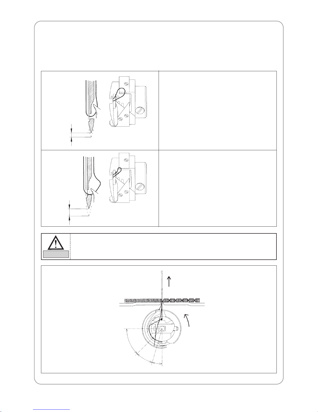
8.2.8) Relationship between the take-up lever and the hook
Hook point timing is directly related to thread tension and thread breaks. The following pictures show the
location of hook when the take-up lever starts to move up from the lower dead stop (main shaft rotation angle:
291°).
Too small
Too large
1) Hook timing is fast (in the A range)
The hook starts to take the thread from the takeup lever. Loop is small because the upper thread
is pulled. Stitches are made but stitch tension is
bad. Thread skips occur, where hook fails to go
through the loop.
2) Hook timing is slow (in the B range)
The hook starts to take the loop before the takeup lever goes up. Thread skips don’t occur, but
thread breaks occur, because the take-up lever
moves faster than the thread coming off the hook.
(A)
(C)
(B)
In normal hook timing, the hook should be in the (C) range.
NOTE
Page 39
39
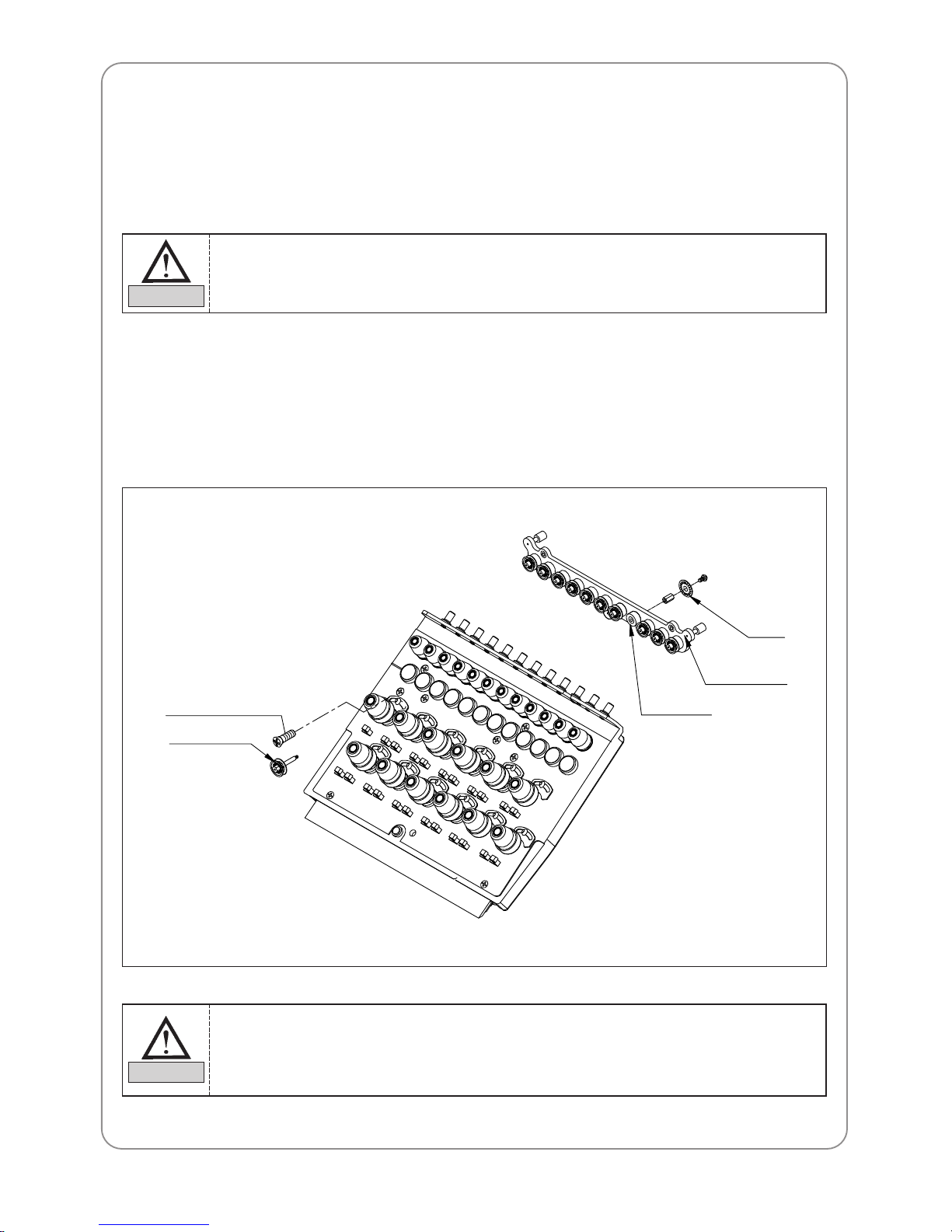
8.3.2) Disassembling the thread detector
You will need to disassemble the thread-break detector unit when you to have to clean it for more smooth
rotation. Remove the cover of the thread tension adjusting plate, separate the cables of the thread detection
board, and unfasten the roller base bolts. The entire unit will be disassembled including the rollers and bush
bearing.
8.3) THREAD DETECTOR ASSEMBLY AND FUNCTIONS
8.3.1) Functions of the thread detector
The thread detector prevents bad embroidery by detecting breaks of the upper or the lower threads. The thread
detection roller performs the detection.
Roller base bolt
Thread detector roller
Bush bearing
Roller base
Film
Wrong detection can occur if the thread detection roller does not rotate smoothly.
CAUTION
1) When assembling the thread detection roller, check between the sensor groove and the film
on the thread detection board.
2) Thread detection may not work according to the location of the thread detection board.
3) You can adjust the location of the board using the board base bolts.
CAUTION
Page 40
40
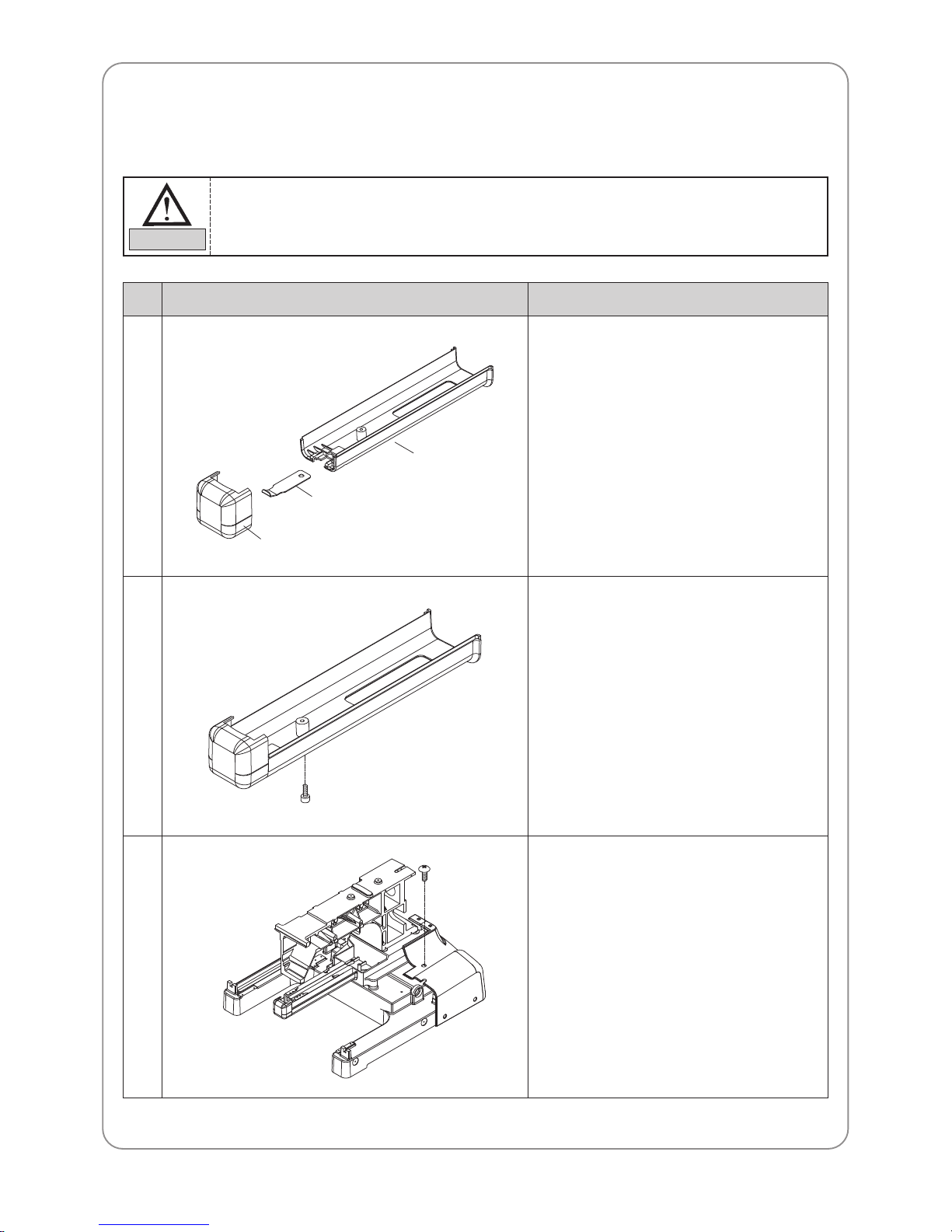
8.4) COVER ASSEMBLY
8.4.1) Assembling the cover
PictureNo Instructions
Hook cover
Hook cover spring
Bed cover(B)
①
②
③
– Assemble the hook cover and bed cover
(B) using the hook cover spring.
– Assemble after completing “①” using the
M3×L8 wrench bolt.
– Tools to use : 2.5mm T-wrench
– Assemble the body cover (C) on the rear
side of the body.
– Tools to use : (+) screwdriver
– Joining bolts : M4×L10 trust bolt
Body cover (C)
Assembly
1) Follow the order of assembly.
2) Do not put excessive pressure or force on the plastic cover.
3) Use appropriate tools to prevent breaking or damage of the cover.
CAUTION
Page 41
41
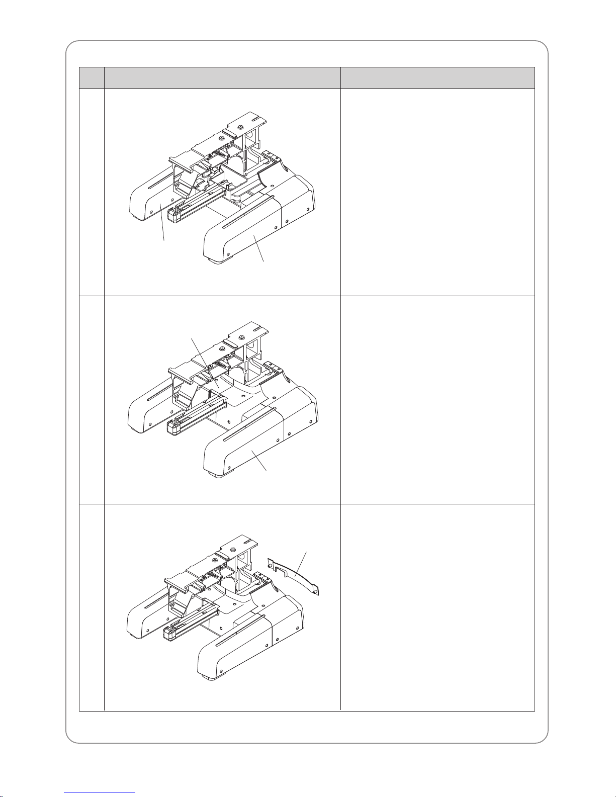
PictureNo Instructions
④
⑤
⑥
– Assemble the body cover (L-A)(R-A).
– Tools to use : (+) screwdriver
– Joining bolts : M4×L10 trust bolt
– Assemble the body cover (L-B)(R-B).
– Tools to use : (+) screwdriver
– Joining bolts : M4×L10 trust bolt
– Assemble the body cover (D).
– Tools to use : (+) screwdriver
– Joining bolts : M4×L10 trust bolt
Body cover (R-A)
Body cover (L-A)
Body cover(L-B)
Body cover(R-B)
Body cover(D)
Page 42
42
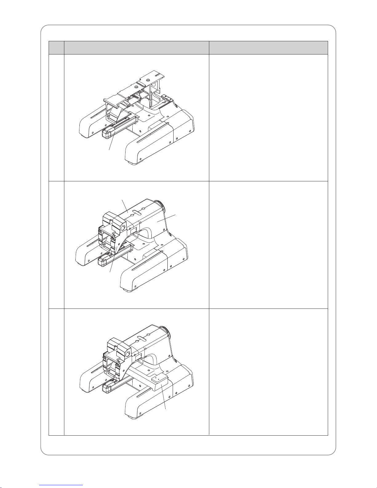
PictureNo Instructions
⑦
⑧
⑨
– Assemble the bed cover (A).
– Tools to use: (+) screwdriver
– Joining bolts: M4×L10 trust bolt
– Assemble the arm cover (L)(R-A)(R-B).
– Tools to use: (+) screwdriver
– Joining bolts: M4×L10 trust bolt
– Assemble the X-drive cover to the
machine.
– Tools to use: (+) screwdriver
– Joining bolts: M4×L10 trust bolt
Bed cover (A)
Arm cover (L)
Arm cover (R-B)
Arm cover (R-A)
X-drive cover
Page 43
43
MAINTENANCE AND INSPECTION
09
9.1) CHECK POINTS FOR REGULAR INSPECTION
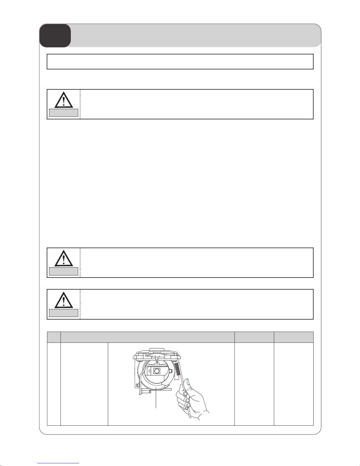
9.2) CLEANING
Use the air compressor to clean each part of the machine.
9.1.1) Clean, oil, and grease the set parts of the machine on a regular basis.
9.1.2) Inspect tension of each driver belt.
9.1.3) Failure to perform regular inspections can cause the following.
– Corrosion of P/C circuit board
– Damage to the semi-conductor on P/C circuit board
– Malfunction of the floppy disk drive
– Ill connection of the connector
– Abnormal wear-outs of machine parts due to insufficient oiling and greasing
1 Around the hook Every day
①
Major parts for cleaningNo. Cleaning cycle Fig.
Hook
①
Consumable parts shall not be guaranteed even in warranty period.
1) Machine and electricity safety rules must be observed during the inspection.
2) Make sure to turn OFF and STOP the machine when performing inspection.
CAUTION
1) Turn OFF the main power before inspecting or cleaning of the machine.
2) Adjust the cleaning cycle according to the conditions of use and to the environment.
CAUTION
SWF is not responsible for machine damages or malfunction caused by insufficient regular
inspection.
CAUTION
Page 44
44
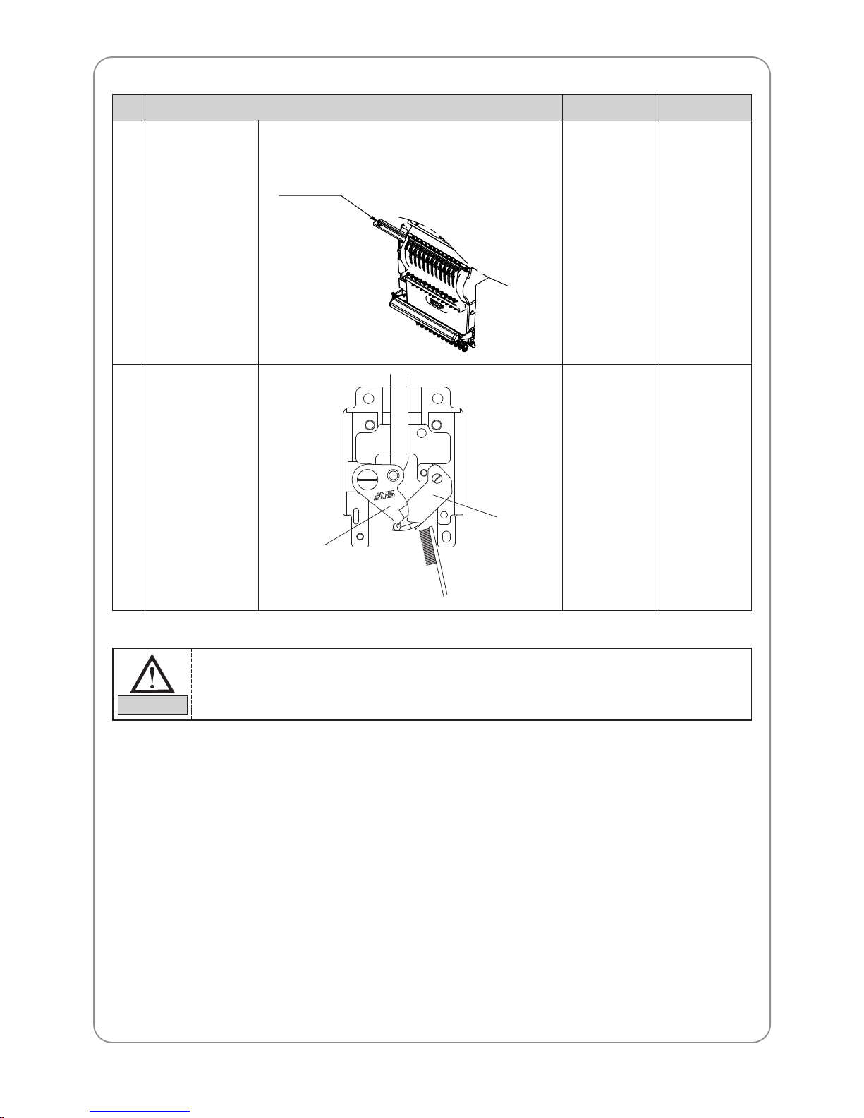
2
Guide rail to the
take-up lever of the
head
Once a week
②
Major parts for cleaningNo. Cleaning cycle Fig.
3
Around the movable
blade and the fixed
blade
Once in 3 days
③
Fixed blade
To clean, remove the needle plate and pull the movable blade to the front (see picture). After
the cleaning, assemble back in the reverse order.
CAUTION
Take-up guide rail
Movable blade
Page 45
45
9.3) OIL SUPPLY
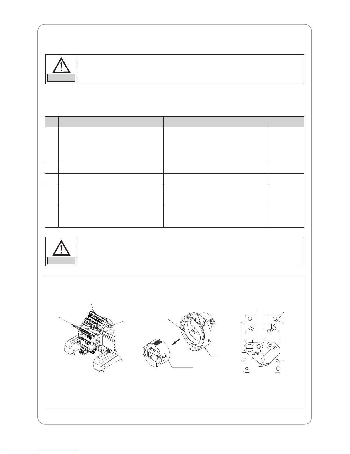
9.3.1) Oil supply
Use the SWF-provided sewing machine oil (Spindle Oil) or ISO-level VG18.
1
Oil tank
Guide rail to the take-up lever Once a week
②
2
Needle plate lubrication hole
Take the bobbin case out of the hook. Feed
small amount of oil on the raceway.
Juncture of the movable blade and the fixed
blade in the trimming unit
Once every three days
Once in 3-4 hours
Once in 2-3 weeks
③
④
⑤
3
4
5
Once in 2 weeks
[ Fill the tank when the oil level is below the
red line ]
①
No. Oiling cycleWhere to oil Fig.
1) Make sure to turn the power OFF during oil supply.
2) SWF is not responsible for machine damages or wear-outs caused by insufficient oiling.
CAUTION
1) Excess oil may stain the thread and the fabric.
2) Run the machine without stitching for 2-3 minutes after oiling.
3) Excessive oiling in the hook may cause trimming problems and thread breaks.
CAUTION
①
②
③
⑤
Raceway ④
Bobbin case
Hook
Page 46
46
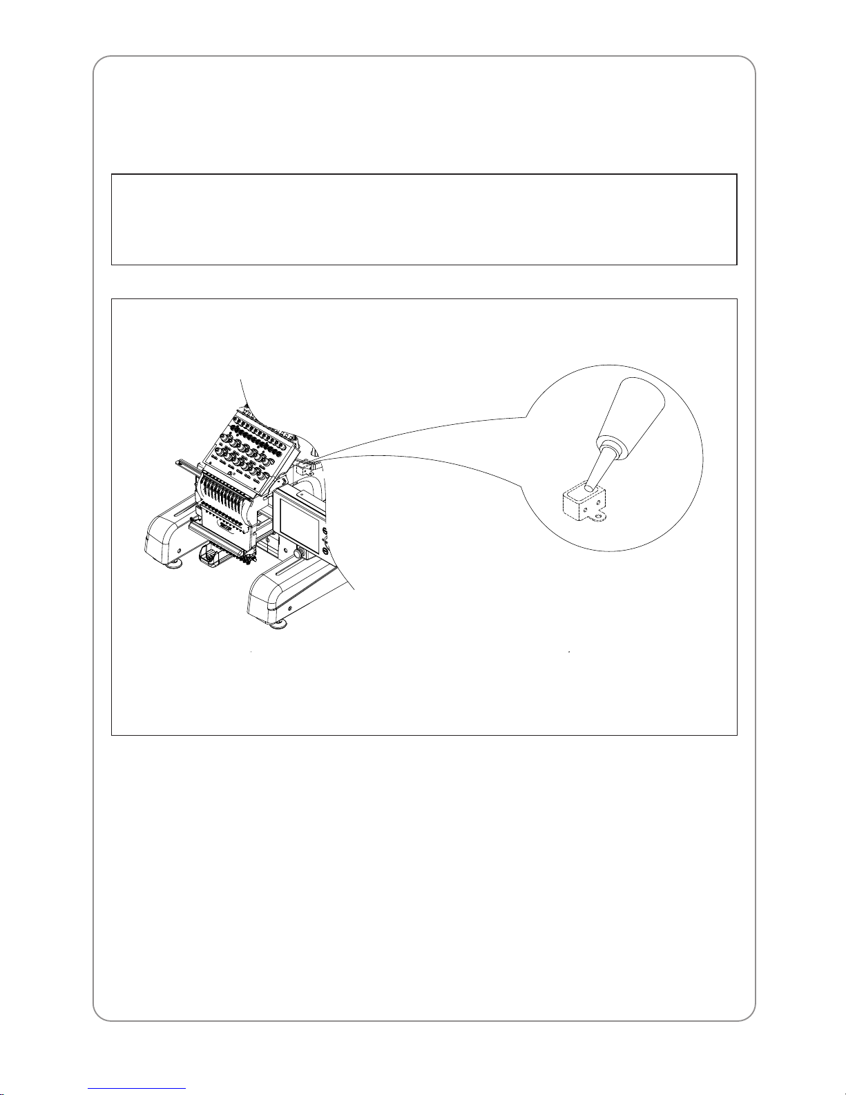
9.3.2) Oiling each part of the arm
Filling the oil tank will automatically oil each part of the arm.
Be careful not to overfill the tank.
• All bushings in the upper shaft
• Crank road of the needle bar
• Controller and the needle bar
• Shaft of the take-up lever driver lever
• Shaft of the presser foot driver lever
• Shaft of the needle bar driver
• Shaft of the presser foot driver
• Bushing in the lower shaft
Page 47
47
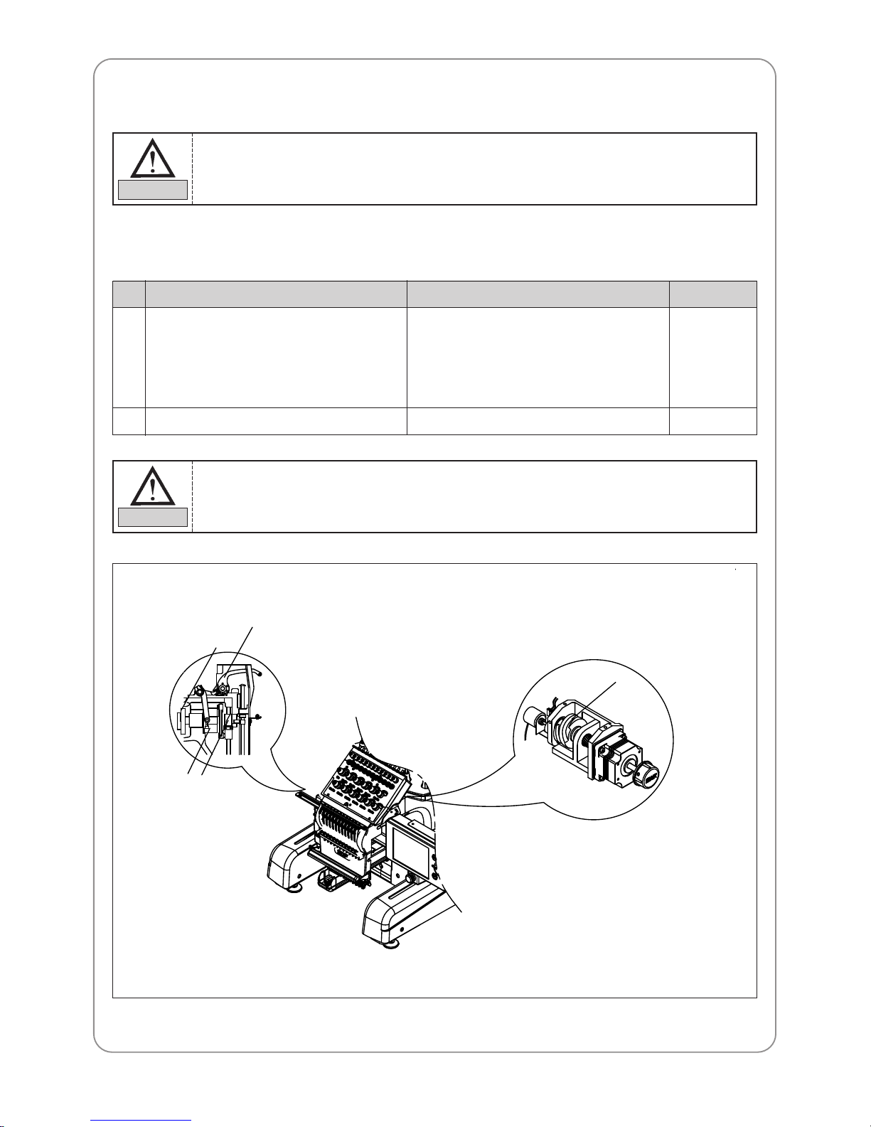
9.3.3) Greasing
1) Greasing the inside of the arm
Use high-quality mineral-based lithium grease.
1
Inside the arm
– Take-up lever drive cam
– Boss of the take-up lever
– Needle bar controller
– Presser foot driver cam
Color change cam Once in 3 months
⑤
2
Once in 3 months
①
②
③
④
No. Greasing cycleWhere to grease Fig.
Make sure to turn OFF the main power during the grease supply.
CAUTION
Regular greasing prevents machine noise and abnormal wear-out.
CAUTION
①
②
④
③
⑤
Page 48
48
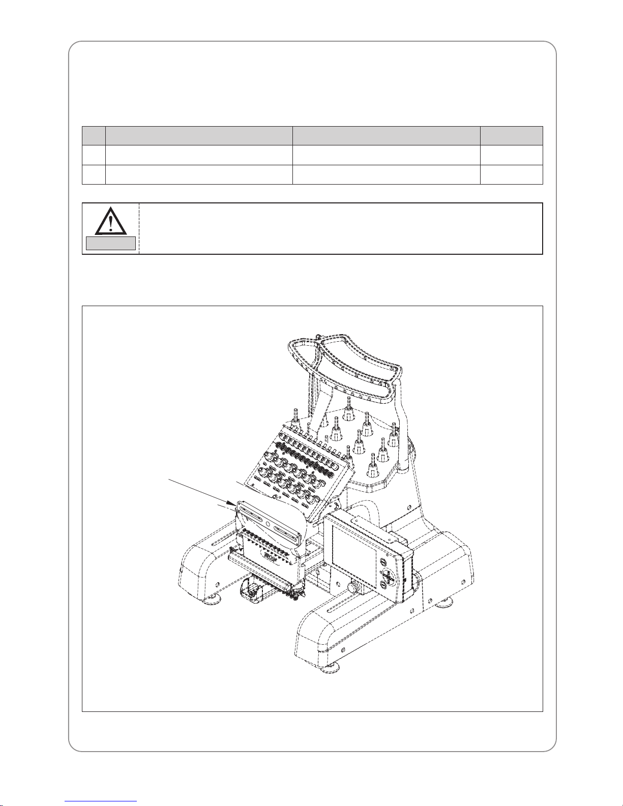
2) Greasing the head
Use lithium-type grease (JIS No.2) – Albania No.2.
■ Greasing the head drive LM guide
Head drive LM guide Once in a month
①
1
X, Y drive guide rail Once in a month
②
2
No. Greasing cycleWhere to grease Fig.
Regular greasing prevents machine noise and abnormal wear-out.
CAUTION
①
Page 49
49
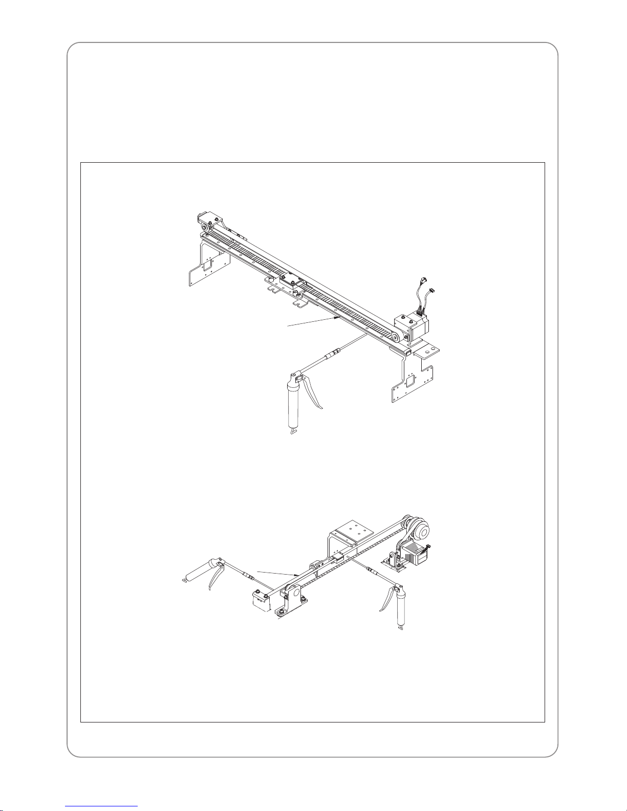
3) Greasing the X, Y drive guide rail
– Disassemble the X-drive frame cover and body covers L-A, R-A.
– Push the guide block farthest to one side.
– Lift the timing belt with one hand and grease the entire part of the drive guide rail
– After greasing, assemble the cover back in the reverse order.
■ Layout of X, Y drive guide rail
■ Zoom-in the guide rail layout
Y-drive
②
②
Page 50
ADJUSTING MAJOR PARTS OF THE MACHINE
10
50
Turn OFF the main power when adjusting the machine.
CAUTION
Clean the machine regularly to prevent thread tails clouding around the lower thread holder.
Such may undermine the function of the lower thread holder.
CAUTION
10.1) TRIMMER ADJUSTMENT
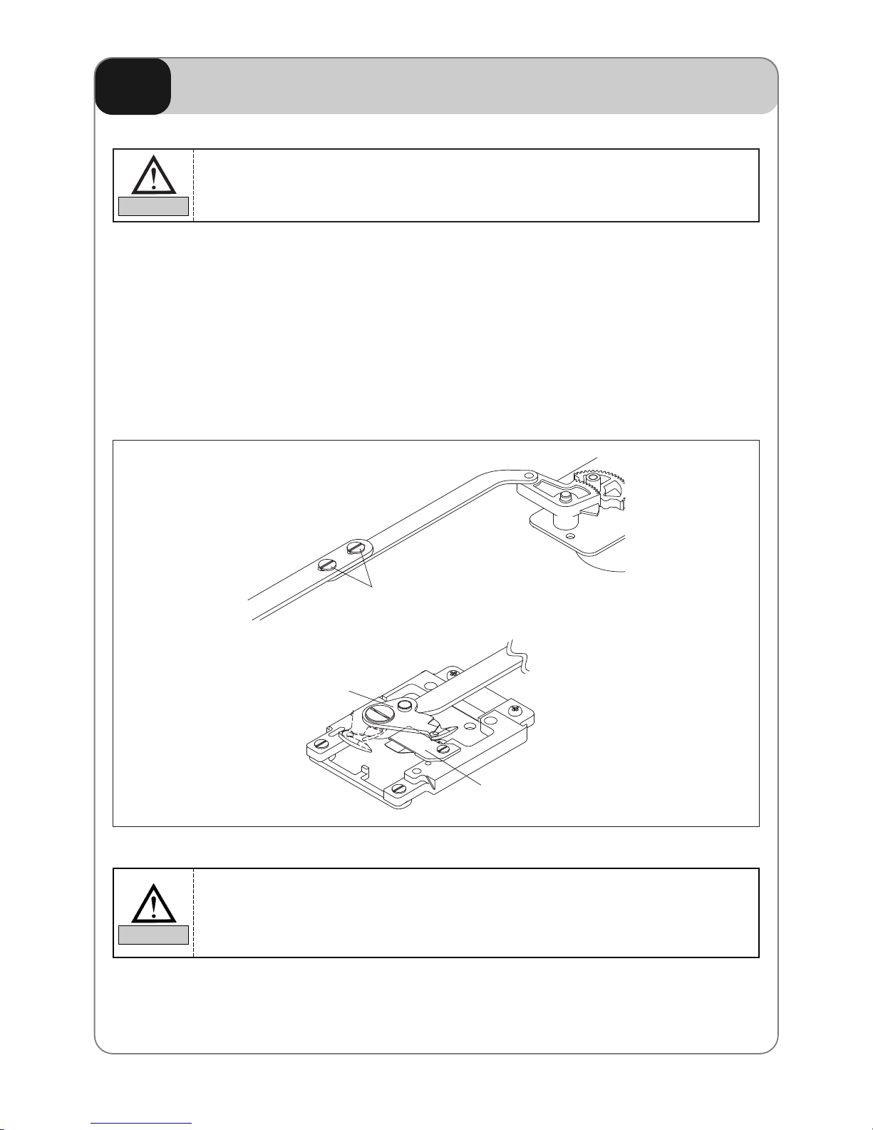
10.1.1) Moving Place Position Adjustment
– The proper position of the moving blade is that the cutting point of the fixed blade should be at the end of the
fixed blade. If the moving blade is not properly positioned, such problems as upper thread separation and cut
skipping could occur.
– If the moving blade is not properly positioned, loosen the fixing screws for the moving blade links (A), (B)
and turn on the power. Then the trimming motor moves to the default point. Place the moving blade at the
end of the fixed blade, and then tightly fasten the fixing screw .
Movable blade
Fixing screw for moving blade link
Fixed blade
Page 51
51
10.2) ADJUSTING UPPER THREAD HOLDER
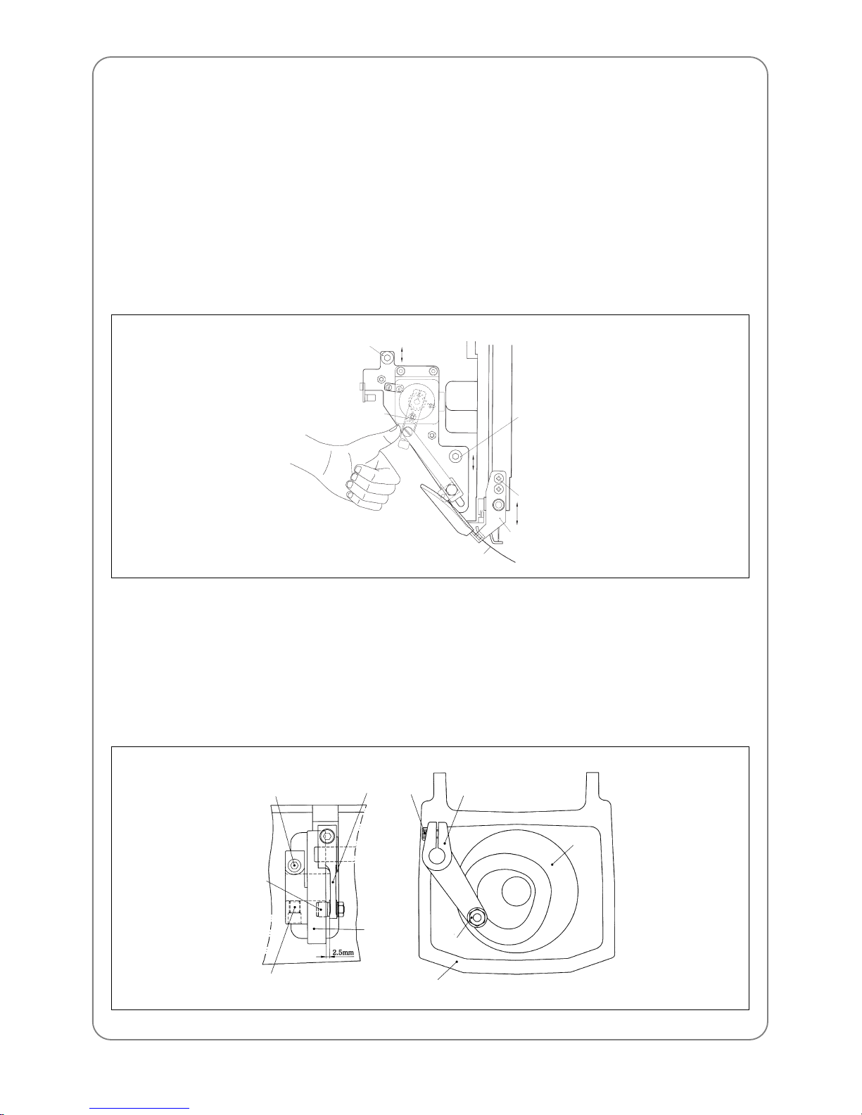
10.2.1) Adjusting
Unfasten the base bolts of the upper thread holder base. Press with your hand the connecting lever of the motor
shaft and fix the base at a position where hook of the upper thread holder completely passes through the center
of the needle. Unscrew the bracket bolt so the bracket does not load the upper thread holder. Fasten the bracket
bolt where the upper thread holder operates smoothly .
10.2.2) Checking
After adjustment, check if the upper thread holder operates smoothly when the needle is changed, by changing
the color.
10.3) ADJUSTING LOW-NOISE PRESSER FOOT
10.3.1) Setting the low-noise presser foot
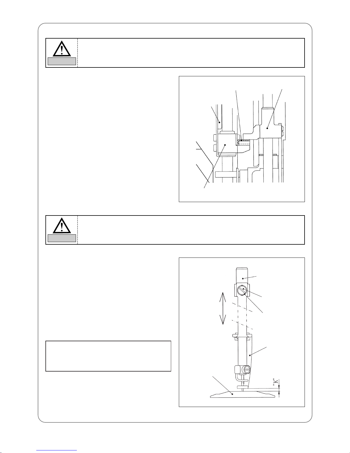
Unfasten all screws of the presser foot cam and drive lever (s). Turn the hand pulley to the maximum lower
position of the needle bar (180°). Turn the cam with the roller inserted to it. When the roller reaches a position,
where it aligns with the maximum eccentricity of the cam (roller is farthest from the arm in the picture), fasten
the screws tightly .
Bolt on the upper
thread holder base
Bolt on the upper thread holder base
Bolt on the upper thread holder bracket
Upper thread holder bracket
Upper thread holder
Connecting lever of
the motor shaft
Cam #1 screw
Drive lever(s)
Cam #2 screw
Roller
Cam
Screw
Drive lever(s)
cam
Roller
Arm
Page 52
52
– Turn the hand pulley and set it at 100°. Fix the
hand pulley and turn the cam. Fix the cam when
it reaches a position where the presser foot
holder sits on the rubber of the presser foot
stopper. Fasten the cam#1 screw. Turn the hand
pulley and fasten the cam#2 screw .
10.3.2) Adjusting the height of the presser
foot
Turn the hand pulley and set to the lowest point of
the needle bar (180°). Uncover the head plate and
unfasten the presser foot screw . Adjust the space,
using the gauge, between the lower part of the
presser foot and the upper part of the needle plate
to the appropriate height (K). Make the adjustment
for each presser foot.
[Standard set-up]
“K” : Needle plate for cap
→ 1.5mm
Needle plate for flat → 1mm (tubular)
Presser foot
stopper rubber
Presser foot
controller bracket
Presser foot
controller
Presser foot holder
Presser foot holder
Screw
Washer
Presser foot
Needle plate
When fastening the drive lever(s), pull the shaft and make sure there is no gap between the
lever and the arm.
CAUTION
Roller should not be inserted too deep into the cam.
CAUTION
Page 53
53
10.4) RELA TIONSHIP BETWEEN
PRESSER FOOT AND NEEDLE
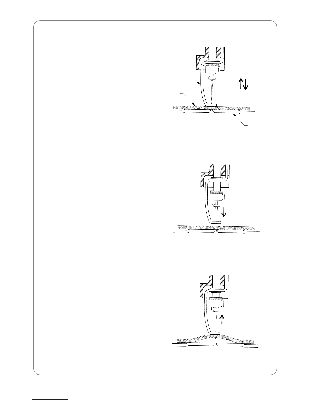
10.4.1) Relationship between presser foot,
needle, and embroidery fabric
For stable stitching, the presser foot must be
pressing the embroidery material before the needle
pierces into the material. The same is true for
when the needle comes out of the material.
10.4.2) When the presser foot is too high
– Needle in
The picture shows the presser foot fails to press
the work material when the needle pierces into
the fabric, causing an unstable needlework.
– Needle out
The picture shows the presser foot fails to press
the work material when the needle comes out of
the fabric. The embroidery material is lifted up
along with the needle, making a gap between
the fabric and the needle plate. This may cause
thread breaks, skipped stitches, or unstable
stitching.
Presser foot
Embroidery
fabric
Needle plate
Needle in
Needle out
Needle
in
Needle
out
Page 54
54
10.5) ADJUSTING HALF-TURN FILM
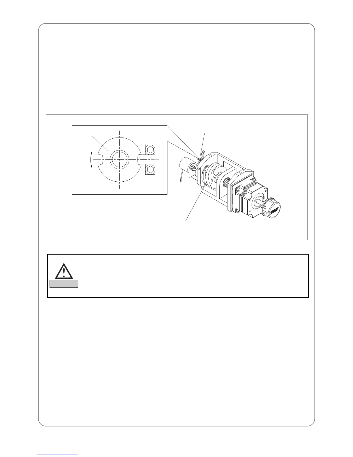
For automatic color change, if the needle is not at the center of the needle hole on the plate, adjust the half-turn
film as below .
– Adjusting the half-turn film
Adjust the cam position using a manual knob so the roller is on the center of the color change cam on the
straight line when the needle aligns with the center of the needle hole on the needle plate. Make an adjustment
so the center of the half-turn film aligns with the center of the half-turn sensor.
Color change cam
Half-turn film
1) Manual color change must be performed at the main shaft angle of 100°. Manual color
change at the main shaft angles other than 100°can cause damage on the controller and the
take-up unit.
2) If you cannot align the needle to the center of the needle hole by adjusting the half-turn film,
call your SWF dealership or a skilled engineer for help.
CAUTION
Half-turn sensor
Page 55
55
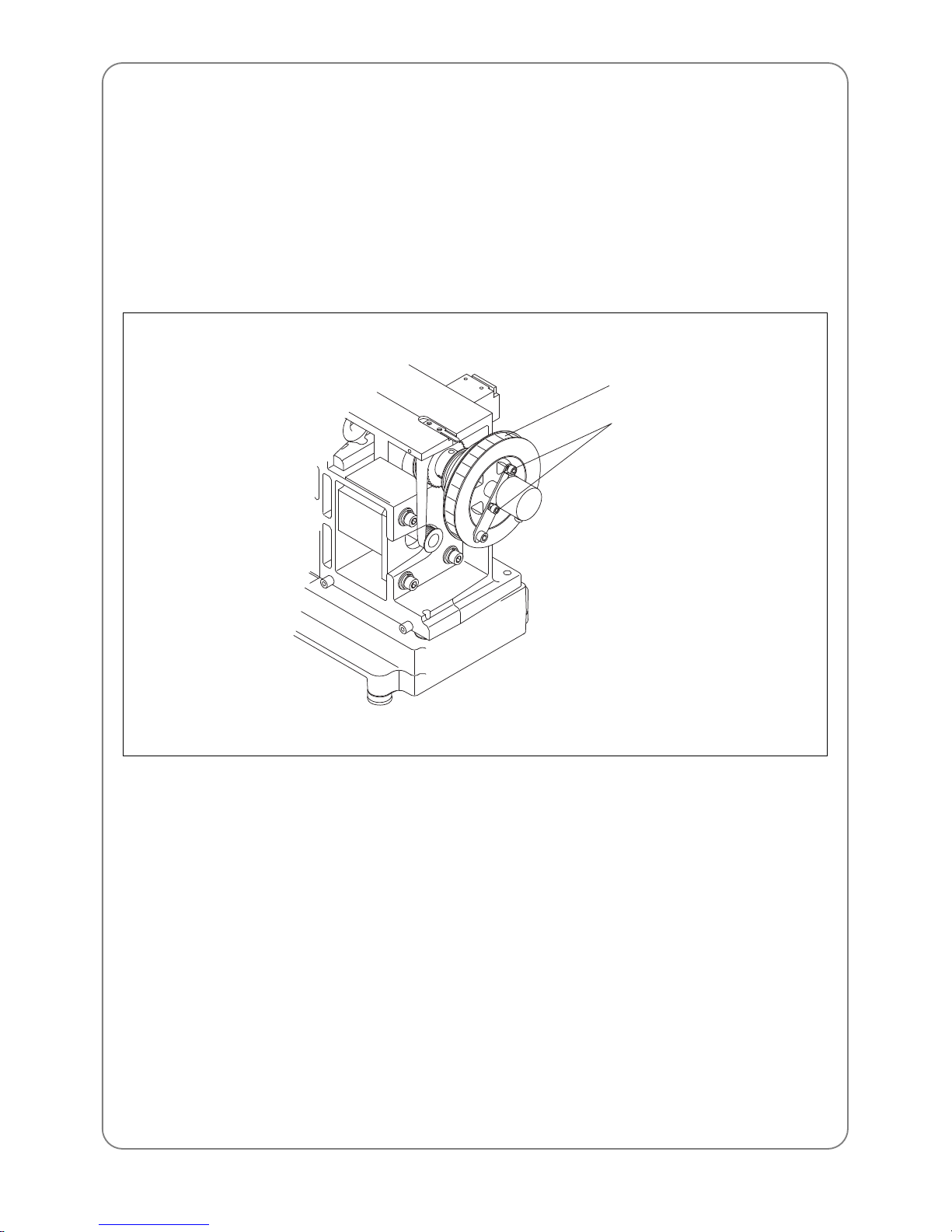
10.6) ADJUSTING ENCODER
Adjust the encoder as below if the needle bar stops at an incorrect position.
– First, unfasten the two encoder coupling screws (2EA).
– Turn the hand pulley, fix the main shaft angle at around 98°, and adjust the encoder. Tighten the screws
when FIX POS light is turned on.
– If you cannot make the adjustment through the encoder coupling, unfasten the two encoder screws, move the
hand pulley , fix the upper shaft angle at around 98°, and adjust the encoder. When the upper shaft stop
position light blinks red, fasten the screws tightly .
Encoder coupling
screws
Hand pulley
Page 56
56
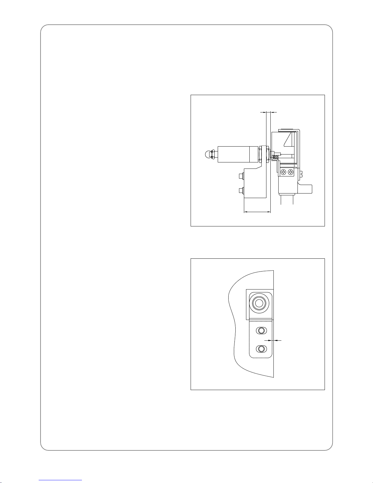
10.7) ADJUSTING JUMP SOLENOID
Solenoid adjustment is required for new or malfunctioning jump solenoids.
10.7.1) Adjusting the standby position (assembling solenoid and bracket)
10.7.2) Adjusting the assembly location (assembling solenoid-attached bracket to the arm)
– Unscrew solenoid nut using the jump solenoid
adjusting spanner and adjust so that the bracket
and the solenoid operation surface are 3.5mm
away . Fasten the nut.
– If the gap is too big, the needle bar controller
can interfere with the solenoid screw and
therefore the needle bar can stop. If the gap is
too small, the needle bar controller can hold the
needle bar even during the jump, causing bad
jumps.
– Adjust so that the processed surface of the arm
is 1mm from the bracket surface. Fix with the
bracket screw .
– If the location is not good, the needle bar
controller can touch the needle bar during the
jumps, making the needle bar work during the
jumps.
3.5mm
22mm
1mm
Page 57
57
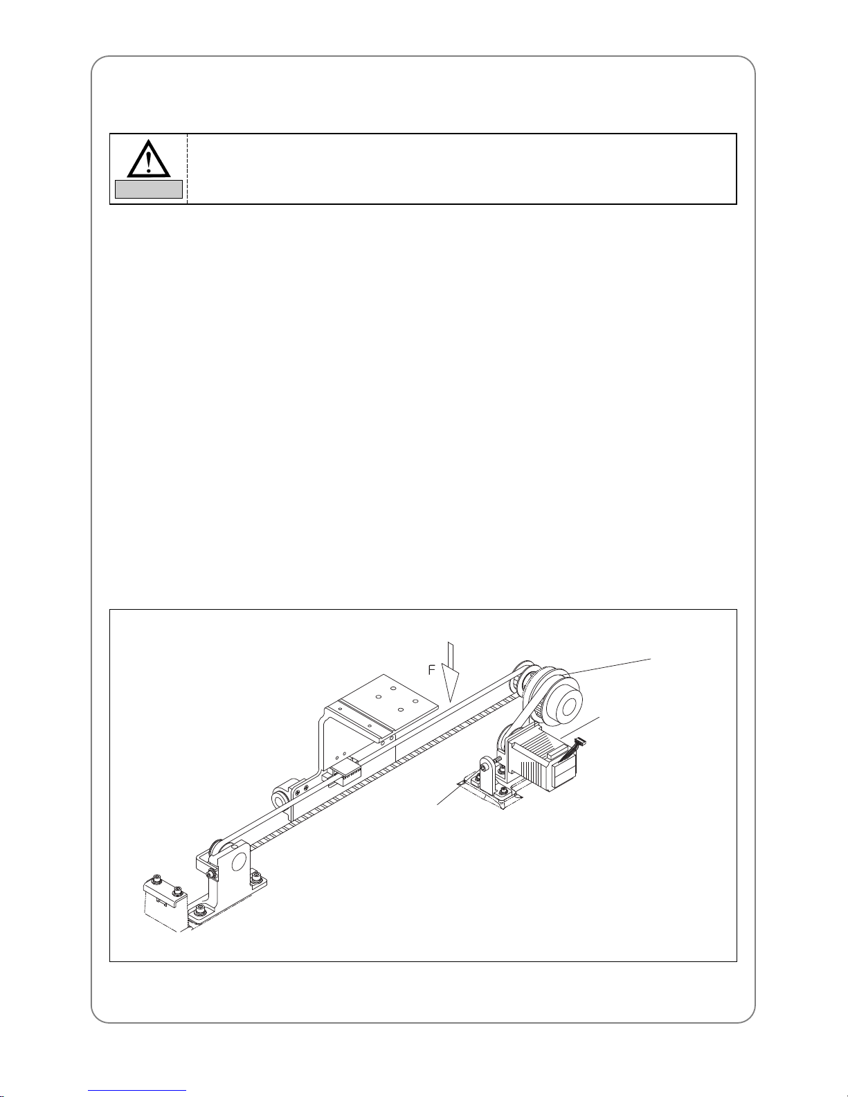
10.8) ADJUSTING TENSION OF EACH DRIVE BELT
10.8.1) Specification of drive belt tension adjusters (sound wave belt tension)
1) Model : U-305 Series Sound Wave Belt Tension Gauge – Standard
2) Manufacturer : UNITTA
10.8.2) Y-axis timing belt
– Push the X driver to the driven pulley and check the timing belt on the Y-axis. Use the sound wave tension
gauge.
– T ension on the Y-axis timing belt should measure 14-15kgf on the sound wave gauge when you pluck the
middle of the belt between the end of the X driver and the drive pulley with your finger or with a similar
tool.
– Input data for the sound wave tension measurer:
• Weight : 003.8gf/m
• Width : 015.0mm/#R
• Span: 488mm
– T o adjust the Y-axis timing belt tension, unfasten the tension base screw and turn the bolt. Turn clockwise to
increase and counterclockwise to decrease the tension.
Tension
adjusting bolt
1) Drive belt tension, as it affects the embroidery quality and machine operation, should be
adjusted only by trained SWF engineers or skilled experts.
2) Make sure to turn OFF the machine during the adjustment.
CAUTION
Driven pulley
Driving Part
Page 58
58
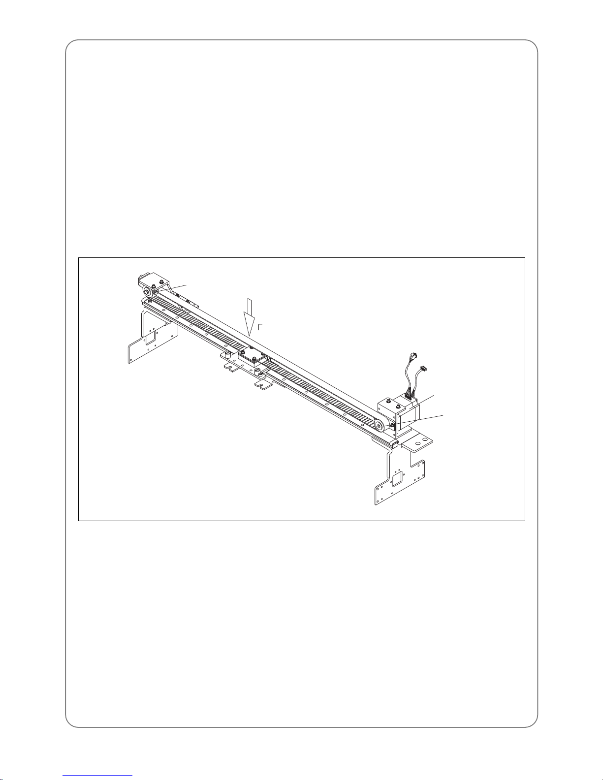
10.8.3) X-axis timing belt
– Push the frame plate fully to the right. Check the timing belt tension on X-axis using the sound wave tension
gauge.
– T ension on the X-axis timing belt should measure 14-15kgf on the sound wave gauge when you pluck the
middle of the belt with your finger or with a similar tool.
– Input data for the sound wave tension measurer
• Weight : 003.8gf/m
• Width : 015.0mm/#R
• Span : 583mm
– T o adjust tension on the X-axis timing belt, unfasten the adjusting shaft nut of tension and adjusting nut.
And turn the tension adjusting bolt. Turn the bolt clockwise to increase the tension and counterclockwise to
decrease the tension.
Drive pulley
Driving Part
Driven pulley
Page 59
TROUBLESHOOTING
11
59
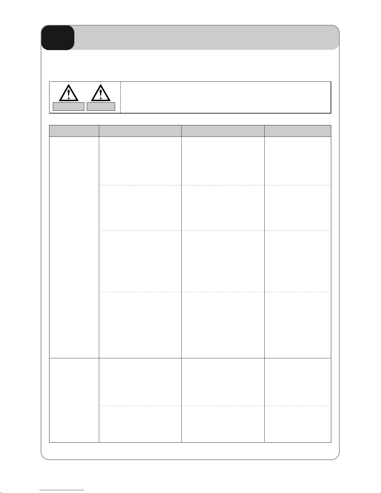
1 1.1) CAUSES AND TROUBLESHOOTING
Inspect/repair the machine by the guideline in machine failures.
CAUTION DANGER
Operation failure
Incorrect Stop
Position
① Loose belt tension or belt
damage
② Power failure or short-circuit
of fuse
③ Failure to detect signals for
needle position or for 1
rotation
④ Frame out of X or Y limit
① Loose tension on main
driver belt
② Incorrect position of encoder
or bad encoder
■ Adjust belt tension/ change
belt
■ Change fuse in the power
socket
■ Manually move color
change. Check if the signal
blinks at the correct needle
position in the operation box
■ Adjust design start point
(Move the frame manually
so the design comes into
the scope)
■ Change belt
■ Adjust position or change
encoder
Check
① main driver belt
② X-Y timing belt
Inspection & Repair CauseError Type Reference
Page 60
60
Bad Color
Change
① Incorrect position of needle
stop
② Failure to sense signals for
needle position or 1 rotation
③ Incorrect position of needle
bar
④ Incorrect position of take-up
lever
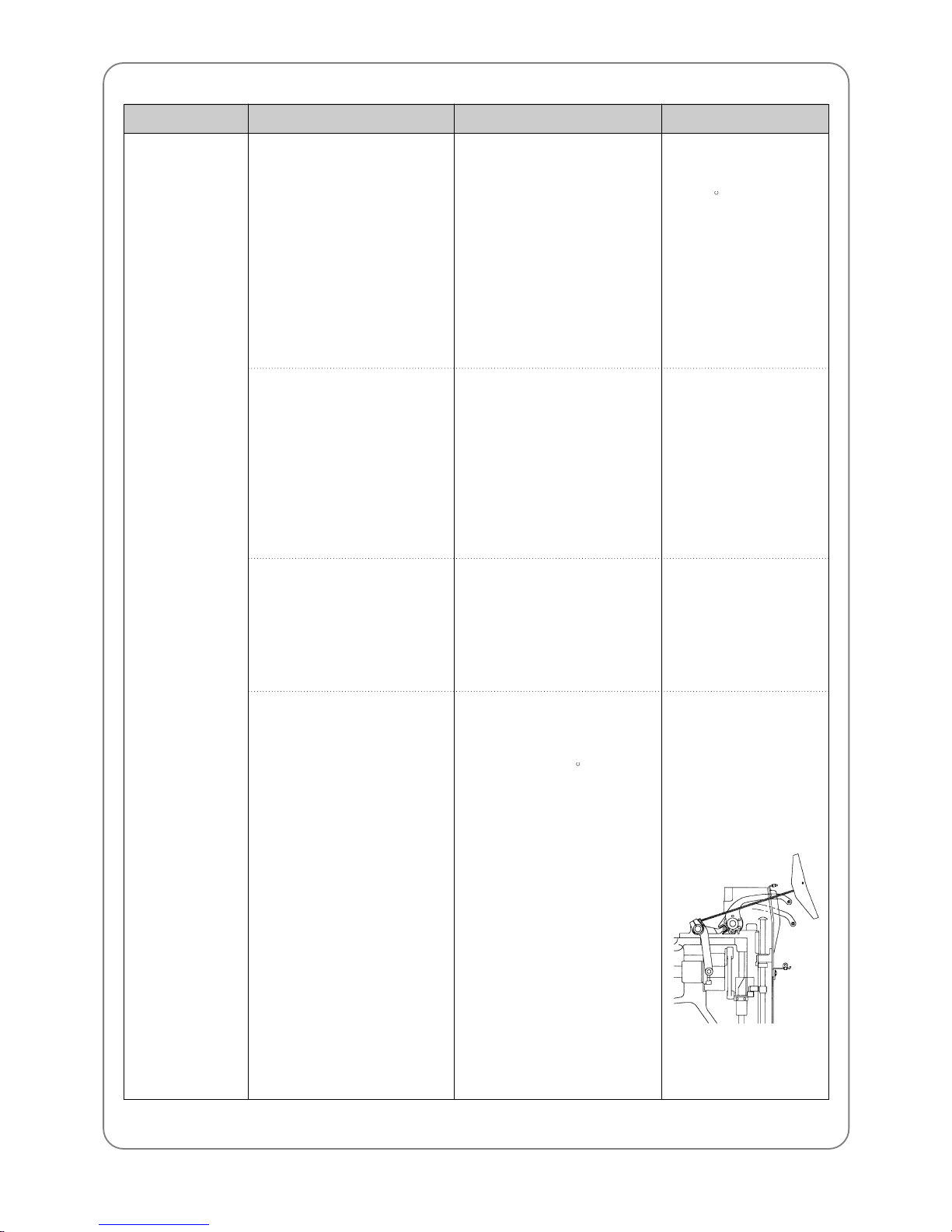
■ Refer to the related part
■ Manually move color
change. Check if the signal
blinks at the correct needle
position in the operation box
■ Set it to the correct position
■ Adjust so the take-up lever
is aligned with other levers
in the stop position (main
shaft angle 100 )
■ Always set the main
shaft angle back at
100 , after moving it
manually for
cleaning, inspection
or repair.
■ How to adjust takeup lever: Unscrew
the lever and adjust it
so it is aligned with
others on the guide
rail.
Inspection & Repair CauseError Type Reference
Page 61

61
Poor detection of
upper thread
Bad jump
Bad stitch quality
① Failure of thread detecting
roller
② Poor connection and bad
quality of tension adjusting
plate
① Bad solenoid and solenoid
wiring
② Bad connection
③ Switch failure on tension
adjusting board and bad
circuit board
① Bad tape data
② Inadequate tension on X-Y
belt
③ Foreign substances in X-Y
rail
④ Failure of X/Y drivers
⑤ Heavy load on the frame
■ Disassemble the roller and
clean the roller and bush
bearing.
■ Check the plate connection
and change the circuit board
■ Check wiring and change
solenoid
■ Check connector
■ Change switch and circuit
board
■ Correct tape data
■ Adjust tension
■ Clean
■ Change X/Y drivers
■ Reduce speed of main shaft
rotation
Inspection & Repair CauseError Type Reference
Page 62

62
Thread breaks ① Stitch is too small/dense for
thread
② Frequent thread break in
the same spot
③ Inadequate needle size for
thread
④ Needle damage (bent, dent,
worn)
⑤ Incorrect needle installation
(height, direction, etc.)
⑥ Dirty needle (adhesive, etc.)
■ Re-punch design
■ Re-punch after checking
design
■ Correct the stitches on
operation box
■ Change needle for the
thread type
■ Change needle
■ Re-install needle
■ Clean or change needle and
hook
■ Check design
■ Use minimum
adhesive for appliqué
Inspection & Repair CauseError Type Reference
Page 63
63
Thread breaks ⑦ Bad quality thread (weak,
uneven thickness, poorly
twisted, old)
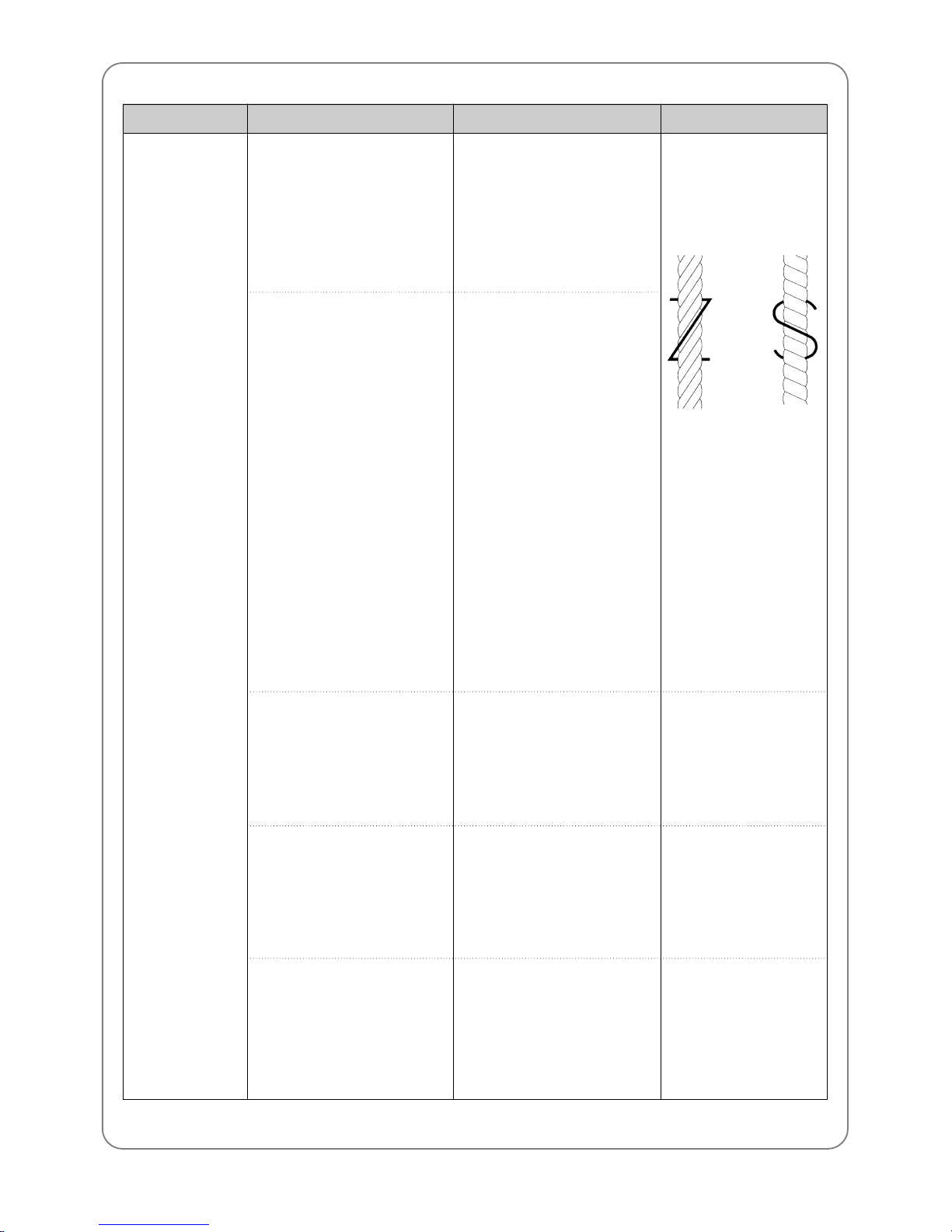
⑧ Right-twisted thread
⑨ Excessive tension on
upper/lower thread
⑩ Tension imbalance between
upper and lower threads
⑪ Excessive tension & stroke
on the take-up spring
■ Change thread
■ Change to left-twisted
thread
■ Adjust tension
■ Adjust tension
■ Adjust tension and stroke
Selecting thread
■ soft, even thickness
tight, left-twisted
■ Z-direction : left
■ S-direction : right
※ left-twist prevents
unraveling in the
counterclockwise
rotation of the hook
Inspection & Repair CauseError Type Reference
Page 64
64
Thread breaks ⑫ Dent on thread path on
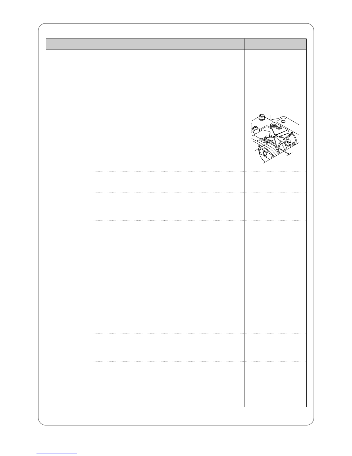
hook and bobbin case
⑬ Narrow space between
hook holder and groove for
hook holder
⑭ Insufficient oil in hook
⑮ Poor timing of needle and
hook
⒃ Incorrect lower dead stop
⒔ Dent on thread path
⒕ Fabric moves on the
frame/plate
⒖ Inadequate height of
presser foot
(does not press the work
material)
■ Remove dent or change the
case
■ Adjust space
■ Oil the raceway of hook
■ Adjust needle-hook timing
■ Adjust the lower dead stop
■ Check:
① Thread path in presser
foot
② Around needle hole on
needle plate
③ Thread guide on the
head
④ Thread path in tension
adjuster
⑤ Thread path in upper
thread holding device
■ Fix the material firmly
■ Adjust height of the presser
foot
■ Check rotary hook
■ Set it at 0.5-0.7mm
for smooth feeding of
upper thread
Inspection & Repair CauseError Type Reference
Hook
Holder
0.5~0.7mm
Page 65

65
Skipped
Stitches
① Bent needle
② Inadequate needle size for
thread
③ Incorrect installation of
needle
④ Poor timing of needle and
hook
⑤ Large gap between needle
groove and hook point
⑥ Incorrect lower dead stop
⑦ Damaged hook point
⑧ Thread feeding is interfered
⑨ Inadequate thread
(twist, elasticity, and
flexibility)
⑩ Excessive tension or stroke
on the take-up lever spring
⑪ Fabric moves with needle -
weak or damaged presser
foot (spring)
■ Change needle
■ Change needle to
appropriate size
■ Adjust installation
■ Adjust needle-hook timing
■ Adjust the gap
■ Adjust the lower dead stop
■ Use whetstone to adjust
hook point or change hook
■ Adjust thread tension
For lower thread, change
bobbin or bobbin case
■ Select right thread for
embroidery
■ Adjust stroke or tension of
the spring
■ Change presser foot spring
Inspection & Repair CauseError Type Reference
Page 66

66
Poor stitch
tension
Needle breaks
① Weak upper thread tension
② Uneven upper thread
tension due to foreign
substances
③ Weak lower thread tension
④ Uneven lower thread
tension
⑤ Thread thickness
⑥ Poor timing of needle and
hook
⑦ Insufficient oil in hook
① Bent needle
② Bad quality needle
③ Tip of the needle is worn or
bent
④ Inadequate needle size
⑤ Needle touches the hook
point
⑥ Incorrect installation of
needle
⑦ Needle touches the needle
hole on the needle plate
■ Adjust tension
■ Clean main and sub tension
adjusters in the thread
tension adjusting plate
■ Adjust lower thread tension
■ Clean bobbin case and
check tension on bobbin
spring
■ Change to quality thread
■ Adjust timing
■ Oil the raceway of hook
■ Change needle
■ Space the needle and the
hook point
■ Correct the installation
■ Check if needle plate is
unscrewed
■ Adjust the position of the
needle bar
Inspection & Repair CauseError Type Reference
Page 67
67
Puckering
Trimming failure
① Excessive thread tension
② Excessive pressure of
presser foot
③ Needle failure -
worn out/damaged needle
tip
needle is too large for
thread
④ Needle hole is too large for
needle
① Poor connection, bad
quality of trimming solenoid
② Bad connection
③ X, Y driver TR damaged
■ Adjust tension
■ Change presser foot spring
■ Change needle
■ Use adequate size of
needle
■ Check and change solenoid
and solenoid connection
■ Check connector
■ Change X, Y driver
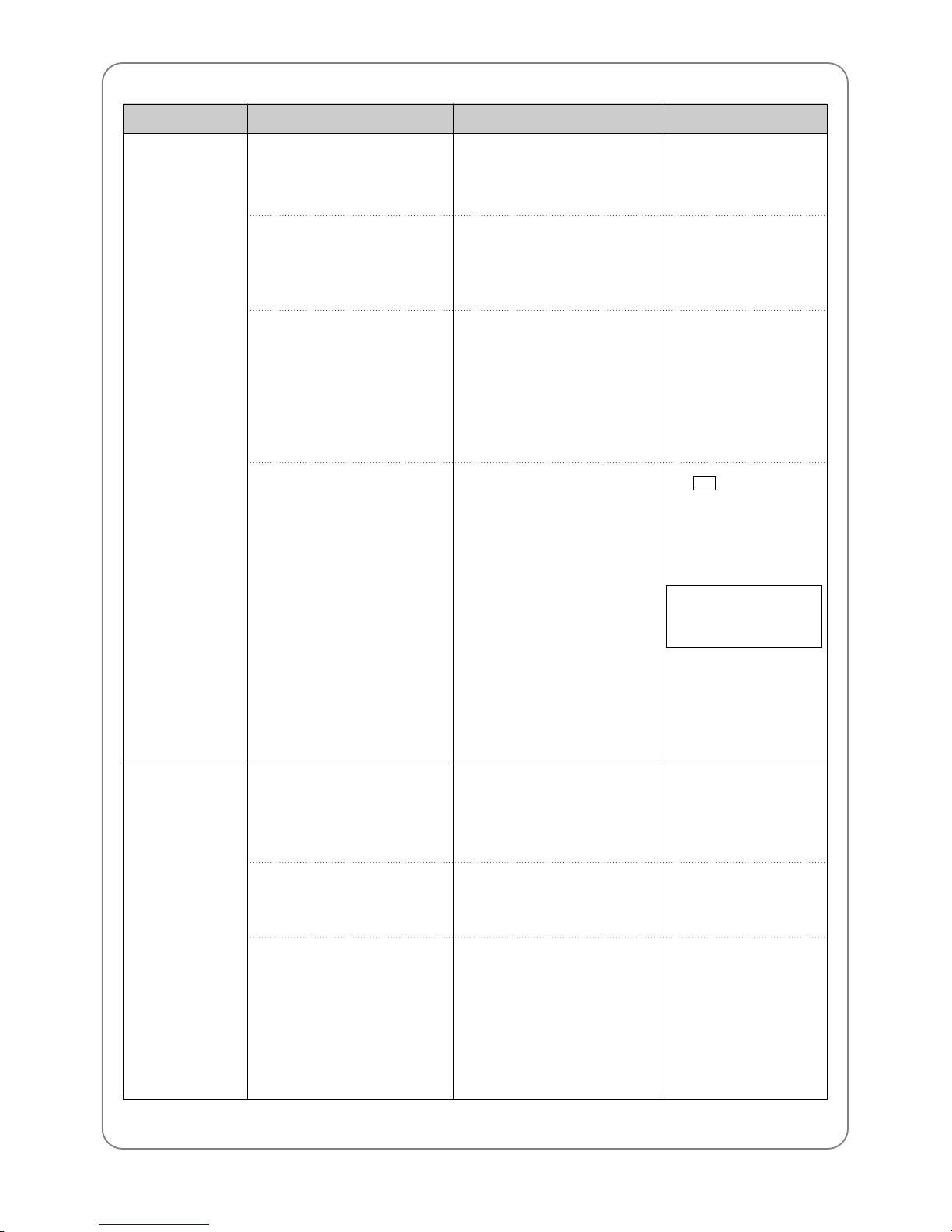
■ SWF needle
holes are 2.0mm
large. SWF
specification for
needle & thread are:
Inspection & Repair CauseError Type Reference
Cotton : #50~70
Rayon : #75~120
Needle : DB×K5 #9~#14
Page 68
68
Short upper
thread after
trimming due to
separation failure
Thread break
before trimming
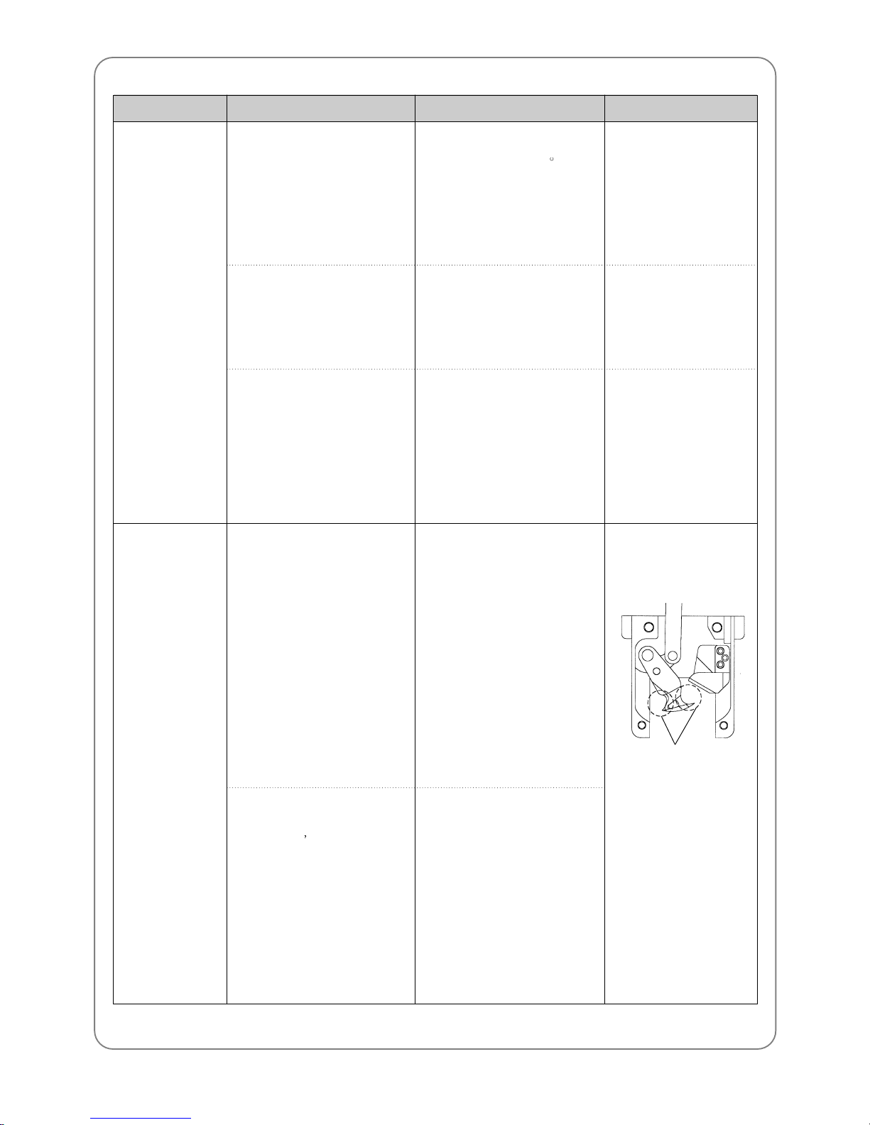
① Movable blade is too fast or
too slow to separate the
upper thread
② Incorrect position of picker
③ Picker failure
① Upper thread is too short
• check main and sub
tension adjuster
• dent or damage of
movable blade
② Lower thread is too short
• doesn t unwind smoothly
• too weak or too elastic
■ Adjust insert angle of
movable blade (295 )
■ Adjust picker position
■ Check and change X, Y
drivers
■ Adjust upper thread tension
■ remove dent using
whetstone or sandpaper or
change movable blade
■ adjust or change bobbin
case spring
■ change lower thread
■ Check fuse spec.
■ Too short lower
thread cannot make
stitches right after
trimming
Inspection & Repair CauseError Type Reference
Check for dent
Page 69

69
Short upper
thread after
trimming
Thread is not cut
when trimming
① Upper thread is trimmed too
short and comes
unthreaded in the next
embroidery
② Upper thread is trimmed too
long and thread tail remains
on the embroidery
① Failure of movable and fixed
blades
② Loose cross tension of the
blades
③ Movable blade damaged
④ Incorrect return position of
movable blade
■ Check upper thread tension
■ Set [LONG] or [MEDIUM]
length of trimmed thread in
SET-UP 3
■ Set [MEDIUM] or [SHORT]
length of trimmed thread in
SET-UP 3
■ If upper thread is held due
to narrow velcro space in
upper thread holder, clean
the velcro
■ Check screws of the related
parts
■ Check tension of fixed blade
■ Change movable blade
■ Adjust the position of
movable blade
■ The default set-up is
MEDIUM.
■ Check fuse spec.
Inspection & Repair CauseError Type Reference
Page 70
70
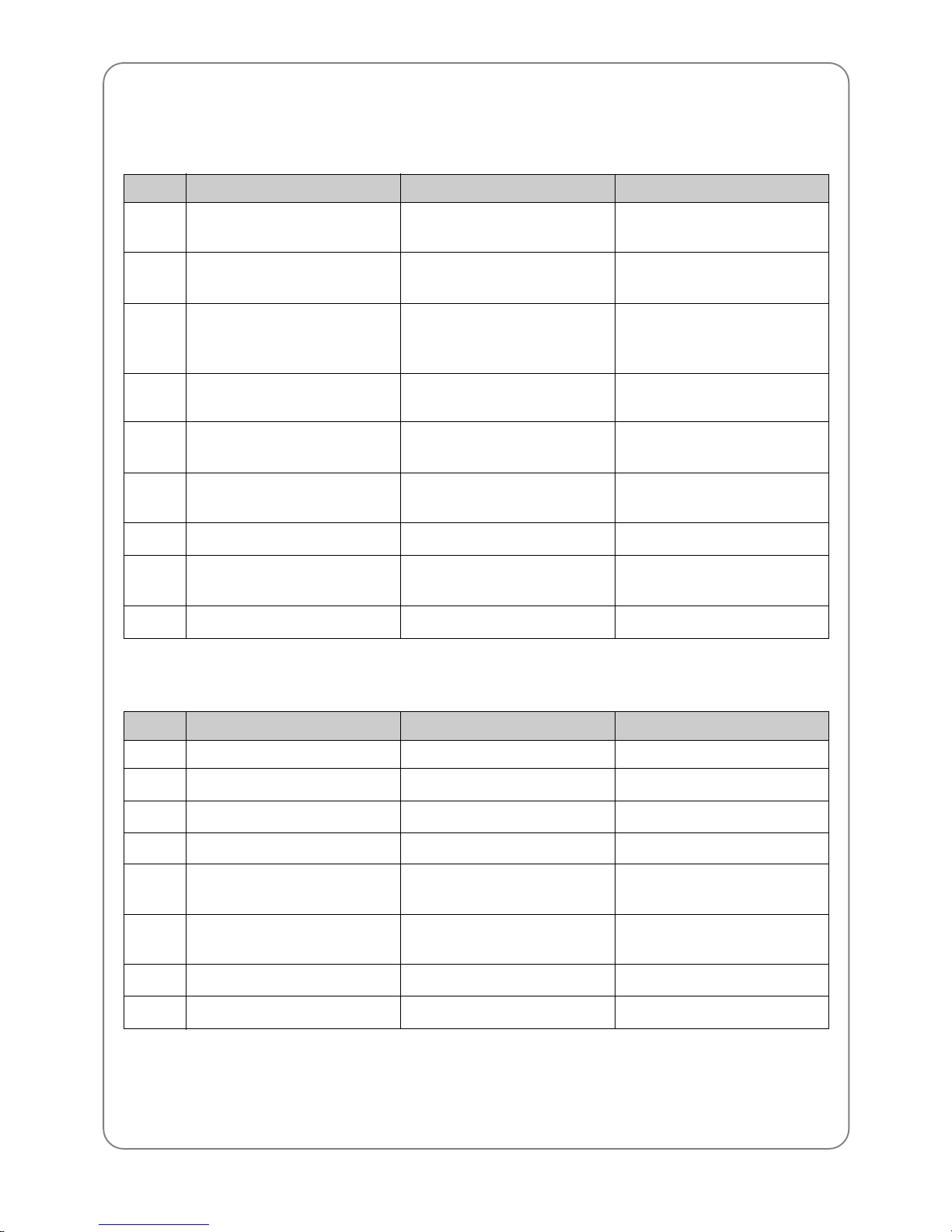
1 1.2) ERROR DISPLAY AND TROUBLESHOOTING
11.2.1) Main shaft motor and others
100
101
102
103
104
105
107
108
109
Main shaft stop
Main shaft motor drive
Main shaft motor overload
Trimming return
START switch
STOP switch
Valve
Air pressure
AC line
Main shaft doesn’t stop at 100°
Error in main shaft motor driver
Thread tangles in the hook
Error in needle bar controller
Thread tangle in trimming
Trimming sensor doesn’t return
when trimming
START is pressed when turning
power on
STOP is pressed when turning
power on
Valve is opened
Air pressure is below standard
(Sequin)
Problems in the joint board
Adjust the main shaft at 100°
using lever.
Turn the main switch off and on
again.
Check hooks of all heads. Turn
the switch off and on again.
Check for errors in the trimming
system
Check START – connector
connection
Check STOP – connector
connection
Replace the joint board, etc.
No. Error Description Troubleshooting
11.2.2) X, Y-axis motors
200
201
202
203
204
205
206
207
(+X) frame limit
(-X) frame limit
(+Y) frame limit
(-Y) frame limit
X-axis driver
Y-axis driver
Wiper return
Trimmer return
Frame reaches +X limit
Frame reaches -X limit
Frame reaches +Y limit
Frame reaches -Y limit
Error in X-axis driver
Error in Y-axis driver
Wiper motor doesn’t return
Trimmer solenoid doesn’t return
Move the frame -X
Move the frame +X
Move the frame -Y
Move the frame +Y
Turn the main switch off and on
again
Turn the main switch off and on
again
Repair the wiper mechanism
Repair the trimmer mechanism
No. Error Description Troubleshooting
Page 71
71
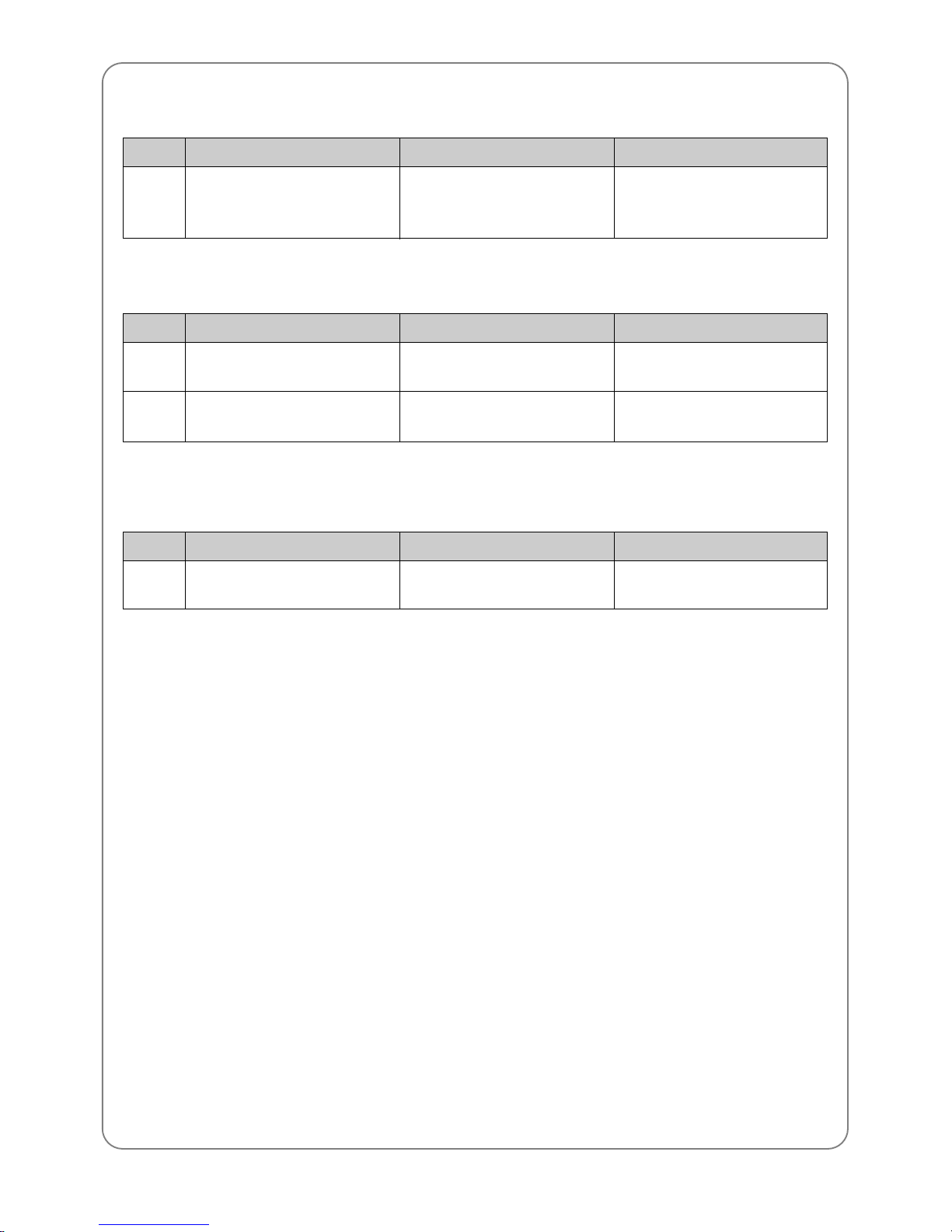
11.2.3) Color change
300 Needle bar position
Needle bar doesn’t come to
correct position when changed
Move the needle bar manually.
Check the load. Position it at the
correct location.
No. Error Description Troubleshooting
11.2.4) Encoder
400
401
Main shaft encoder A
Main shaft encoder Z
Error in signal in main shaft
encoder A
Error in signal in main shaft
encoder Z
Check encoder connection. Turn
the main switch off and on again.
Check encoder connection. Turn
the main switch off and on again
No. Error Description Troubleshooting
11.2.5) Repetition work
501 Repetition set-up Off the repetition limit
(X set-up)×(Y set-up)>99
Change the set-up to:
(X set-up)×(Y set-up)<99
No. Error Description Troubleshooting
Page 72
72
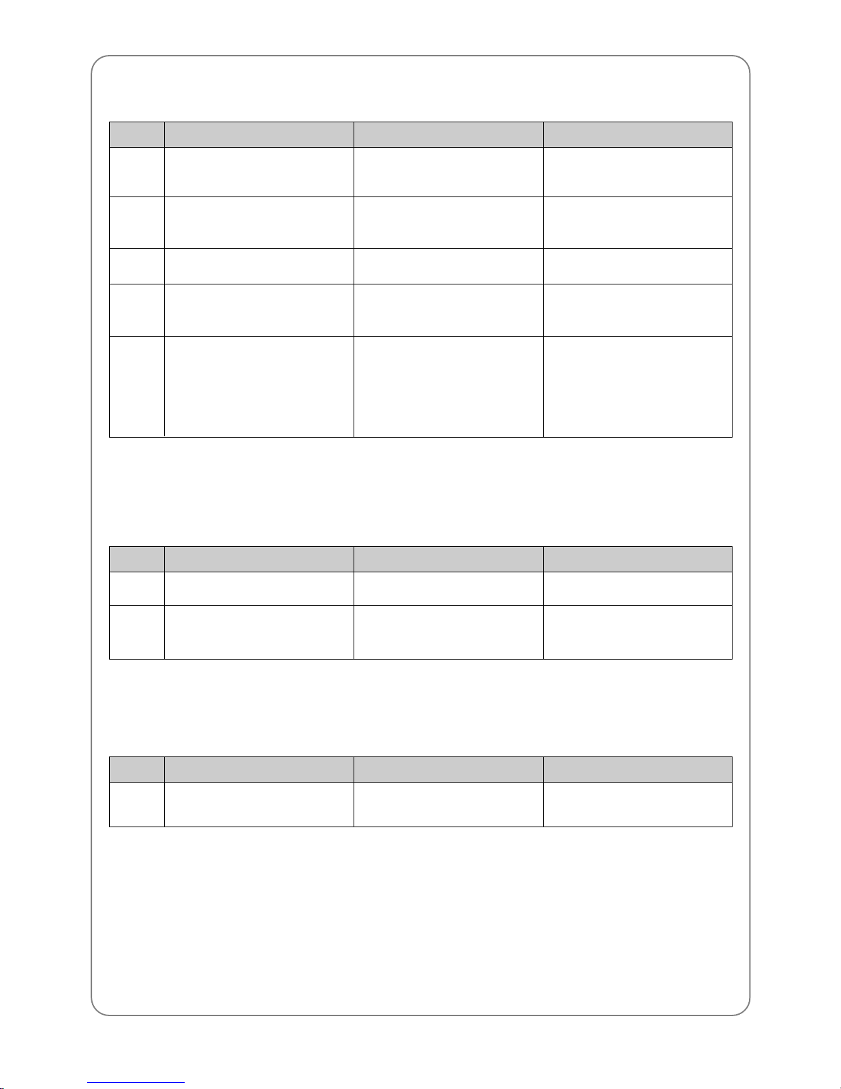
11.2.6) Memory
700
701
702
703
704
No embroidery data in the
memory
Insufficient memory
Memory full
Design memory system
Bad memory battery
No embroidery data in the
memory
Unable to copy data to memory
due to insufficient memory
100 memory rooms are full
Error in copy/delete between
memories
Run out of battery that keeps
memory data during power off.
Unstable storage of data, i.e.
number of stitches, X/Y position,
etc.
Store data in memory via disk
Delete unnecessary data
Delete unnecessary data
RESET or turn the main power
off and on again.
Consult the nearest SWF for
battery change
(if battery outages are frequent,
replace CPU board)
No. Error Description Troubleshooting
11.2.7) Tape reader and communication
630
640
Error in input data
Unable to find network device
Error in the data from tape reader
Network device is not connected
Re-read data from tape reader
Check connection of network
device
No. Error Description Troubleshooting
11.2.8) System installation
800 System installation disk Installation performed without
using system installation disk
Check the system installation
disk
No. Error Description Troubleshooting
Page 73
73
11.2.9) Communication
900
901
902
903
904
905
906
907
908
909
910
911
912
913
914
915
Comm. Error 0
Comm. Error 1
Comm. Error 2
Comm. Error 3
Comm. Error 4
Comm. Error 5
Comm. Error 6
Comm. Error 7
Comm. Error 8
Comm. Error 9
Comm. Error 10
Comm. Error 11
Comm. Error 12
Comm. Error 13
Comm. Error 14
Comm. Error 15
CAN communication error
CAN communication error
CAN communication error
CAN communication error
CAN communication error
CAN communication error
CAN communication error
CAN communication error
CAN communication error
CAN communication error
CAN communication error
CAN communication error
CAN communication error
CAN communication error
CAN communication error
CAN communication error
Turn the power off and on again
Turn the power off and on again
Turn the power off and on again
Turn the power off and on again
Turn the power off and on again
Turn the power off and on again
Turn the power off and on again
Turn the power off and on again
Turn the power off and on again
Turn the power off and on again
Turn the power off and on again
Turn the power off and on again
Turn the power off and on again
Turn the power off and on again
Turn the power off and on again
Turn the power off and on again
No. Error Description Troubleshooting
Page 74
74
SETTING
12
Turn on the main power
Execute installation program
Call the design
Set up conditions for machine operation
Select needle bar
Repetition work
Set-up work position
Start work with a bar switch
Select frame offset function
Gauge, trace, length
measure
Will you do repetition work?
Will you do auxiliary work (gauge, etc.)?
Will you select frame offset?
Read the design from
disk or tape
Is the previous design in the memory?
Is there an operating program in the memory?
Are F1+F2+F7 keys pressed?
Automatic call of design
Automatic call of set-up values
Is there a previous design?
Yes
No
No
Yes
No
Yes
No
Yes
Yes
No
Yes
Yes
 Loading...