

Page 1
F 80A
USER MANUAL IN ORIGINAL
Doc: 101516-GB 1810
Page 2

2
F 80A
Doc: 101516-GB 1810
USE
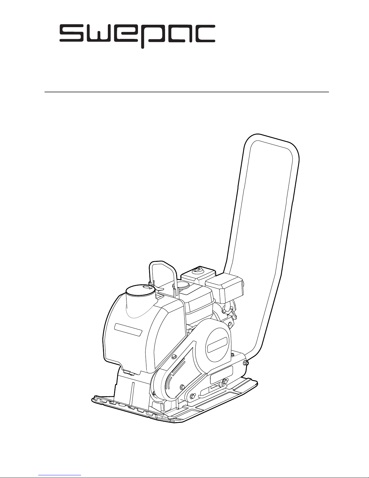
SWEPAC F 80A
is used to pack freshly laid asphalt on pavements and garage
approaches, in connection with roadworks, etc. The machine is
designed to pack small asphalt areas and is particularly suitable
for additional works and repair works. The compact design with
an articulated control handle makes the machine very easy to
manoeuvre. The machine is also suitable for packing sand and
gravel in thin layers.
USE ......................................................................... 2
STANDARDS ......................................................... 3
SIGNS ..................................................................... 4
TECHNICAL DATA ................................................ 5
FUNCTION .............................................................5
TECHNICAL DESCRIPTION ................................ 6
DAILY CHECKS ..................................................... 7
BEFORE STARTING THE ENGINE .....................8
STARTING ..............................................................8
AFTER STARTING ................................................. 8
STOPPING .............................................................. 8
WATER TANK..........................................................9
TRANSPORTATIONS........................................... 10
NOTES..................................................11; 12; 13; 14
EC-DECLARATION OF CONFORMITY.............15
CONTENTS
Page 3

3
F 80A
Doc: 101516-GB 1810
As the sound pressure level at the operator’s ears
exceeds
80 dB (A), ear protectors must be used during operation!
Hand/arm vibrations
The vibration acceleration was measured in accordance
with the ISO 5349 standard during operation on a
graveled surface. The measurement values were
translated into the maximum daily exposure time
for regular usage. For additional information about
vibrations, please confer the regulation AFS 2005:15
from the Swedish Work Environment Authority,
effective July 1st 2005.
Measurement uncertainty ± 0.3 m/s2 in 95% of the
measurements.
Exhaust emissions
F 80Ameet the requirements for exhaust emissions in
acoordance with EU directive 2002/88 Euro2
STANDARDS
Noise
Measurement in accordance with the standard EN 5004 Rev. 1:1998, Annex C:
Measurement uncertainty ± 0.5 dB (A) in 95% of the
measurements.
In accordance with the conditions in Directive 2000/14/
EC, Annex VI, the following values are reported:
F 80A
Sound pressure levelat the operator’s
ears, LpA
90dB (A) LpA
Permitted sound
power level, L
WA
108 dB (A)
Guaranteed sound
power level, L
WA
105 dB (A)
F 80A
Hand/armvibrations, m/s
2
4,6
The maximum daily
exposure time
2,4 h
Page 4
4
F 80A
1 2 3
7 6
4
5
8
MACHINERY
9
Doc: 101516-GB 1810
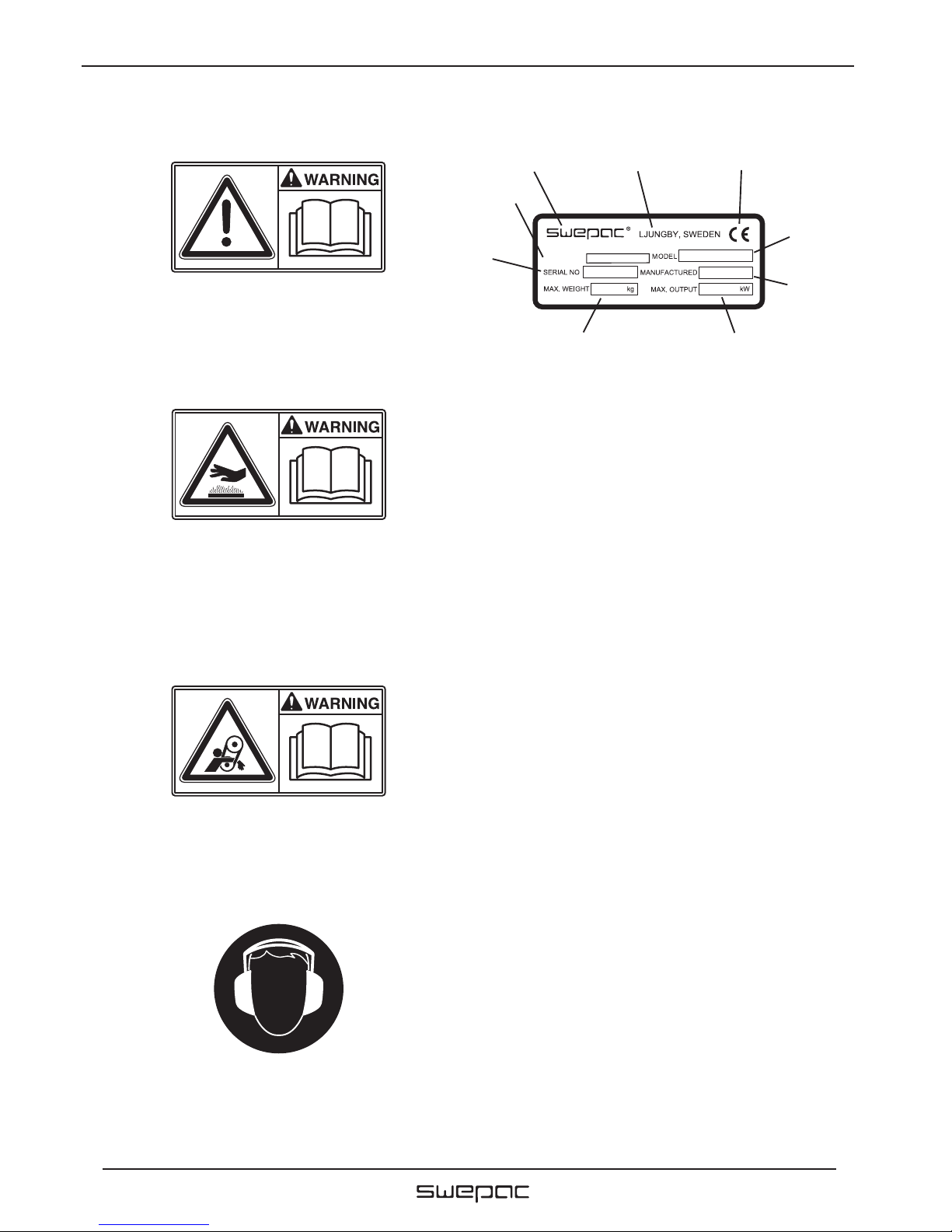
SIGNS
Warning signs Machine Signs
Before use, carefully read the manual and its safety instructions so that you can handle the machine safely. Ensure that
the manual is always accessible.
Belt drive: Keep hands, tools and other objects away from
the belt drive when the machine is on to avoid injury and
damage. See the safety instructions in the manual.
As the sound pressure level at the operator’s ears exceeds 80
dB (A), ear protectors must be used when working with the
machine to prevent hearing damage.
Engine, silencer: to avoid burns or discomfort, do not touch
hot engine parts when the engine is on or when the machine
has recently been used.
1. Manufacturer
2. Place, country of manufacture.
3. CE mark.
4. Model name.
5. Year of manufacture.
6. Max. engine power.
7. Max. weight.
8. Serial number.
9. Machine type
Page 5

5
F 80A
Doc: 101516-GB 1810
TECHNICAL DATA FUNCTION
The machine consists of a base plate with a vibration element
and an upper part cushioned from the base plate.
The upper part include even carrying handle. The lifting eye
include even an water tank bracket.
The power is transmitted from the petrol engine to the vibration
element via a V-belt. To adjust the V-belt loosen the four screws
which holds the upper part to the base plate and pull whole the
upper part backward to the operator.
The engine is tted with an integrated centrifugal clutch. On
account of the direction of rotation and the position of the
vibration element at the front end of the base plate, the
vibrator moves forward under its own power.
The machine’s vibration element stops when the throttle is
switched to idle.
Work with the machine in daylight or other adequate lighting.
All other use is discouraged.
Transport wheels are accessories.
FUEL AND OIL RECOMMENDATIONS
Fuel ..............................Unleaded petrol or alkylate
Engine oil .....................SAE10W-30
Engine oil change: rst oil change after 20 hours then every
100 hours of operation
F 80A
Net weight .................................80 kg
Base plate, w x l .......................430 x 580 mm
Permitted inclination ................18°
Speed .........................................appr 25 m/min
Centrifugal force .......................14 000N
Vibration frequency ..................93 Hz
Drive engine ..............................Honda GX 160
Engine power ............................4,0 kW
Engine RPM ..............................3600 RPM
Fuel tank volume .......................2,5 liter
Fuel type ....................................Unleaded petrol or alkylatet
Water tank volume....................11 Liter
Page 6

6
F 80A
1
2
3
9
4
6
7
8
5
10
Doc: 101516-GB 1810
1. Handle
2. Protective cover
3. Petrol engine
4. Engine plate
5. Centrifugal clutch
6. V-belt
7. Rubber damper
8. Vibration element / Base plate
9. Water tank
10. Lifting eye / Water tank bracket
TECHNICAL DESCRIPTION
Page 7

7
F 80A
1
2
3
1
2
Doc: 101516-GB 1810
DAILY CHECKS
Fuel Check
Check that there is fuel in the tank. Top up if necessary.
Engine Oil Level Check
Check the oil level in the crankcase every day. The oil
must reach the edge of the lling hole when the machine is
on a level surface.
Air Filter Check
The air lter must be checked at least once every working week.
When working in dusty conditions, check daily.
1. Paper element
2. Foam plastic element
Cleaning the air lter
1. Remove the foam plastic element and the
paper element and check that they are
undamaged. Replace damaged parts.
2. Wash the foam plastic element in liquid with
a high ashpoint and let it dry properly. Dip in
engine oil and squeeze dry.
3. Strike the paper element against a hard object
a few times to loosen any dirt.
Oil/Fuel Leakage
Check every day that the engine is not leaking oil
or fuel. If a leak is discovered, the machine may
not be operated until the fault has been remedied.
See also the separate engine instructions!
V-belt Drive
Check the tension and condition of the V-belt regularly.
Adjustment of V-belt tension
Loosen the screws (pos 1) that hold the engine plate.
Loosen the screws (pos 2) holding the cover.
Remove the cover.
Tension the V-belt by pulling the handle on the side of the
engine plate.
Tighten the screws.
Ret the cover.
Rubber Dampers
Check the condition of the rubber dampers (pos 3)
regularly. Replace damaged dampers.
Polyuretan Pad
A polyuretan pad is used for stone paving work to protect
against stones and ground clinker.
Note! Options
Page 8

8
F 80A
Doc: 101516-GB 1810
Oil level
Off
On
Engine power switch
Off On
Fuel cock
Active Not active
Choke
Full RPM
Idle
Throttle lever
BEFORE STARTING THE ENGINE
See Daily Checks on page 8.
STARTING
Switch the engine power switch to “on”. Open the fuel
crane.
See that the lever is in idle speed position.
Active the choke. If the engine is cold, active the choke
completely. Do not use the choke if the engine is warm or if
the air temperature is high.
Start by pulling the starting handle. Pull it rst until the
mechanism engages. Then pull it hard and fast.
AFTER STARTING
Switch the throttle lever to idle.
Open the choke gradually.
Run the engine warm for around 1-5 minutes.
STOPPING
Switch the engine to idle and let it run for a few minutes.
Switch the engine power switch to “off”.
Close the fuel crane.
Page 9

9
F 80A
1
2
Doc: 101516-GB 1810
Push the water tank from
upside down.
The water tank for the F 80A is removable. To mount the water tank do this steps:
Push the water tank down with the side lock pos. 1 open. The rear part of the water
tank´s should be placed in the holder on the bracket.
Make sure that the water tank hangs rmly in the holder, release the side lock and
check that the pin of the side lock hits the hole on the bracket.
MOUNT THE WATER TANK
Start the water supply for asphalt work
Open the water trap pos. 2 by turning it counterclockwise from the
operator´s hole.
Open
Closed
Page 10

10
F 80A
Doc: 101516-GB 1810
TRANSPORTATION
It is easy to remove the handle without tools, and the boot
of a standard car is sufcient to transport the machine.
Lifting by hand
Remove the handle by pushing it forward and pull apart the
shafts so that the fastening tabs release.
Stir the handle slightly sideways so that the handle release.
Caution!The machine must be lifted by 2 persons!
Lift by means of the handle on the back and the front edge
of the machine.
Lifting with crane
Tilt the handle forward.
Fit a lifting sling to the lifting eye and thread the lifting
sling between the shafts of the handle, see illustration
below.
Transport locking
Secure the machine with straps according to illustration
during transportation
Note! Secure it by the base plate and not the rubbercushioned upper part.
Page 11

11
F 80A
Doc: 101516-GB 1810
NOTES
Page 12

12
F 80A
Doc: 101516-GB 1810
NOTES
Page 13

13
F 80A
Doc: 101516-GB 1810
NOTES
Page 14

14
F 80A
Doc: 101516-GB 1810
NOTES
Page 15

15
F 80A
Doc: 101516-GB 1810
EC-declaration of conformity
Manufacturer
Swepac AB
Blockvägen 3
34132 Ljungby
1. Category: Vibratory plate
2. Type: F80A
3. Engine power: F80A 4,0 kW
The product complies with the following directives:
2006 / 42 / EG
2000 / 14 /EG
2004 / 108 / EG
EN 500-1
EN 500-4
Technical documentation held by:
Swepac AB, Blockvägen 3 SE-34132 Ljungby
Tomas Johansson / Product Engineer
Page 16

SWEPAC AB
Address Blockvägen 3, 341 32 Ljungby, Sweden, tel. +46 (0)372-156 00, fax +46 (0)372-837 41, E-mail mail@swepac.se,
Internet www.swepac.se
 Loading...