

Swegon TBLZ-2-75 Instructions Manual
GB.TBLZ275.160517
Instructions for the hand-held micro terminal of the fan
motor control system, TBLZ-2-75
SILVER C
1. General
The hand-held micro terminal is used for setting the motor
parameters of the SILVER C.
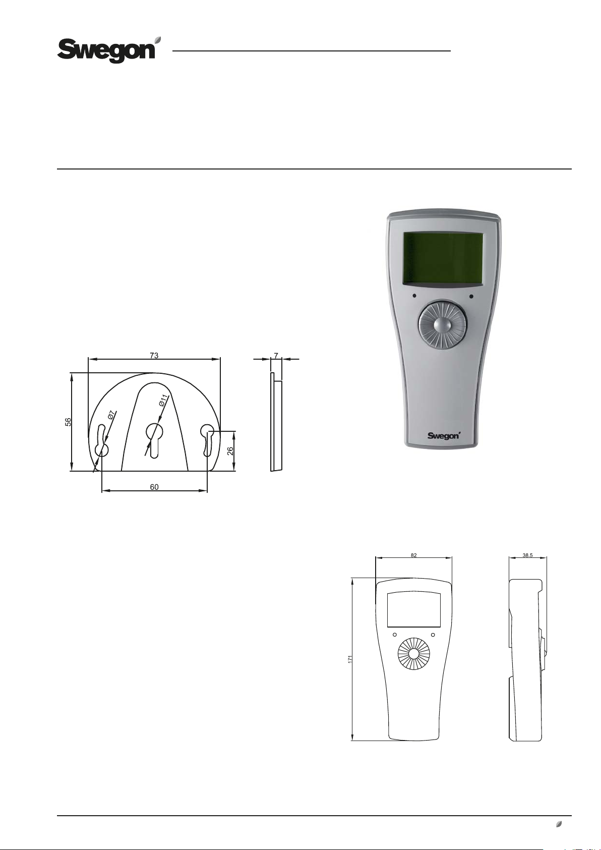
2. Installation
The hand-held micro terminal can be hung in the wall
mounting supplied, See illustration below. Mount the wall
mounting on a flat surface.
To lift the hand-held micro terminal out of the wall
mounting, slide it upward and then draw it out.
3. Technical data
Supply voltage From the motor control system's
wiring terminal
Modbus RTU 2 x RJ12/6/6-pole RS485
Enclosure class IP21
Humidity 10 – 95 % - non-condensing
Ambient temperature -30.. +50 °C (Storage)
0.. +40 °C (in operation)
Dimensions 171 x 82 x 38.5 mm
Weight 150 g
We reserve the right to alter specifications.
www.swegon.com 1
4. Function
The hand-held micro terminal has a display screen with
eight lines, a navigation knob and two LEDs.
Scrolling up and down in the menu is done by turning
the adjusting knob on the hand-held micro terminal, and
selections are entered by pressing on the adjusting knob.
Modification of the selected values is done by turning the
adjustment knob. Select "Exit" to leave the menu.
The hand-held micro terminal communicates with the
motor control system via Modbus commands. Factory
and user settings are stored in the control system. The
settings are preserved in the memory even if the line
voltage is switched off or if the hand-held micro terminal
is removed.
The mortor control system's function selector switch
should normally be set to Position 1, but for communication with the hand-held terminal, the function selector
switch should be set to Position 0.
GB.TBLZ275.160517
The possible settings and displays are shown in the table
on the next page.
Note that you must enter a PIN code in order to open the
Config menu and in this way be able to make changes in
the motor control system configuration. Contact Swegon
to obtain a PIN code.
Table:
MAIN MENU SETTINGS DESCRIPTION VALUE
Status Operation With the Hand-held micro terminal set to the "Modbus" mode, set "Start/Stop in" in the "Start/
Set Setpoint With the Hand-held micro terminal set to the "Modbus" mode in the "Start/Stop"/"Control" menu, set the
% Out Shows the current speed of rotation as a percentage of the range (See Section 10). 0 – 100 %
Rpm Out Shows the current speed of rotation PM: 0 - ?* rpm
Power Shows current input power 0 - ?* kW
Analogue_In 1 Shows the current voltage on the external input for adjustments 0 - 10.0 V
Digital_In 1 Shows current status "LO" = Active
Digital_In 2 Shows current status of Alarm reset "LO" = Active
Digital_In 3 Shows current status of the Firemode jumper. "LO" = Jumper connected
Op. time Shows the current operating time as number of days. 0 - ? days
Op. time Shows the current operating time in minutes. 0 - ? minutes
I out Shows present output current 0 -?* A
V in RMS Shows current input voltage 0 - ?* V
Temp. Shows the current temperature inside the control system. ? - ? °C
FIREMODE Activate the Fire mode. "Fire" from the hand-held micro terminal or external input have higher priority than
Exit Return to the Main menu.
Stop"/"Control" menu.
required set point in the DV in %.
With the Hand-held micro terminal in the "0-10VDC" mode in the "Start/Stop"/"Control" menu, read the
current setpoint in %.
"Normal".
Important! For high internal temperature inside the DV control system, the display window backlight is
turned off when "Fire" is active.
Start/Stop
0 - 100%
"HL" = Inactive
"HL" = Inactive
"HL" = Jumper disconnected
Fire /
Normal
2 www.swegon.com
We reserve the right to alter specifications.
 Loading...