

Swegon TBLZ-2-48-2, GOLD, COMPACT Installation Instructions Manual
Installation Instructions, Control box for Smoke
Function with Damper Exercising TBLZ-2-48-2
GOLD/COMPACT
1. General
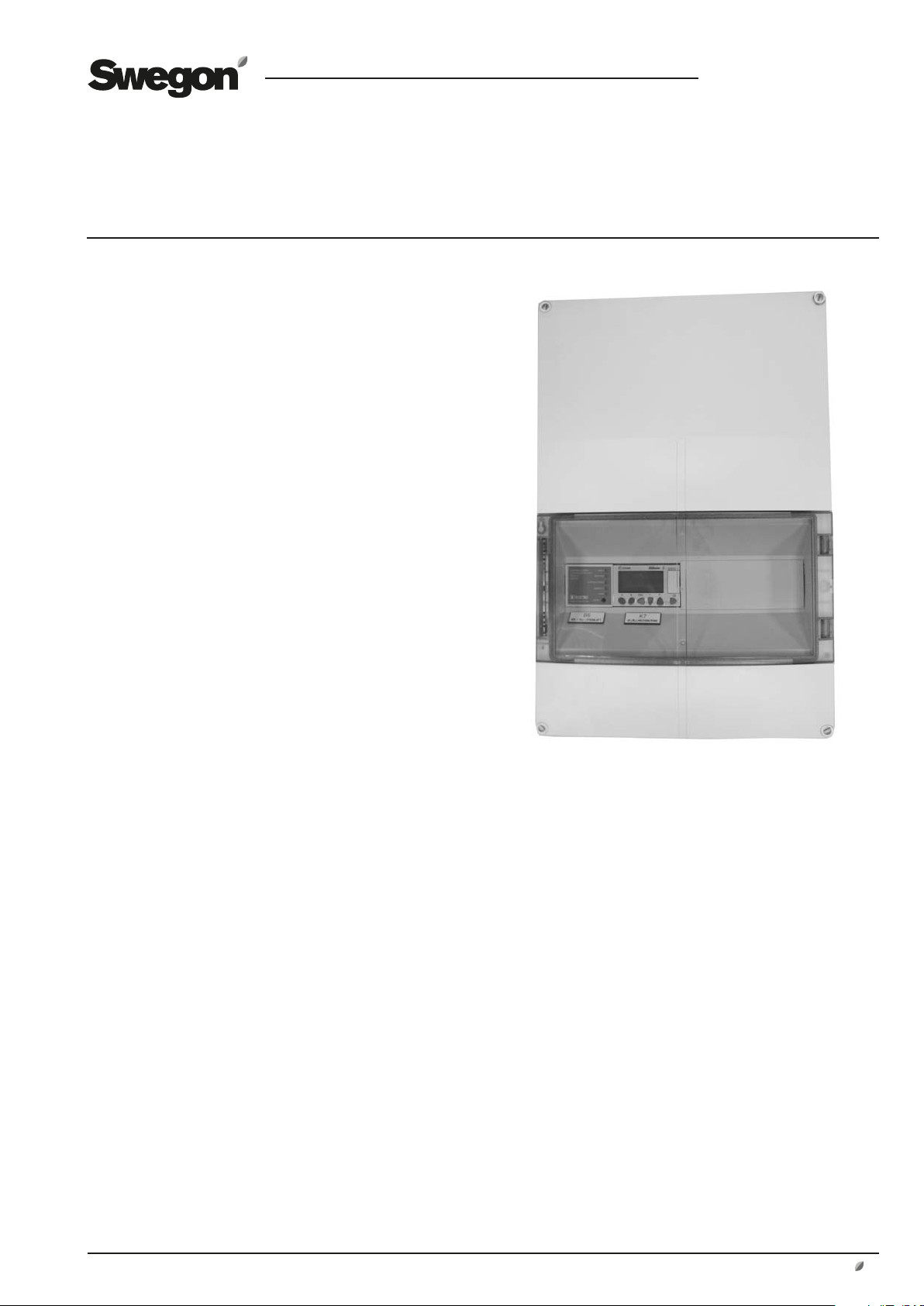
The control box for the smoke function with damper exercising mode consists of a control unit for smoke management, a logic unit and a transformer for exercising dampers, mounted in a box with a transparent cover. Necessary
wiring terminals are provided for connection to external
components.
The control box has knockout holes for cable entry
through grommets.
2. Range of Application
The control box is used together with the TBLZ-2-49-a
smoke detectors. On receiving a fault indication, the control unit is designed to control the dampers, stop the air
handling unit and initiate an alarm.
A preprogrammed logic unit stops the air handling unit
and exercises the dampers at regular time intervals. If the
damper exercising procedure is not satisfactory, an alarm is
initiated. The connected damper actuators must be designed for 24V AC power.
GB.TBLZ2482.120904
3. Function – Control Unit, Smoke
The control unit is designed to comply with the provisions
made upon reliable fire protection together with our smoke
detectors. The unit is equipped with relay contacts for controlling the dampers and fans. In addition to smoke alarms,
the control unit is equipped with service alarm and fault
alarm relays.
In the event of a smoke alarm, a red LED is lit and the alarm
relays are simultaneously de-energised.
In the event of a service alarm from the smoke detector, the
service alarm LED will flash rapidly for one minute. After
that, the service alarm relay will be energised and the LED
will shine constantly. If the service alarm on the detector
returns to normal service, the relay will be de-energised and
the LED will flash slowly: Alarm memory.
If a short circuit or a power failure occurs, this activates the
fault relay and alarm relays, at the same time as the corresponding LED is lit (approx. 10-second delay in the event
of a power failure). If the short circuit clears or the power is
restored, the relay will be de-energised and the corresponding LED will begin to flash slowly: Alarm memory.
To exercise the relays: Press and hold down the reset button
for 5 seconds.
4. Function – Logic Unit for Damper
Exercising
The exercising cycle is activated at regular time intervals in
the logic unit or via signals from an external source transmitted to the unit.
If the damper exercising procedure is not satisfactory, an
alarm is indicated on Logic module K7 and the AHU will
not restart. The alarm is transmitted to the AHU via the
External alarm 2 input.
Alarms can be reset on the control unit or in the handheld micro terminal.
5. Mounting
The control box can be secured to a wall, the air handling
unit or where required by means of four screws.
6. Technical Data
Supply voltage 230 V AC, 50-60 Hz
Power consumption
(control unit)
Power consumption
(logic unit)
Transformer 120VA
Degree of protection IP 65
Ambient temperature 0-50°C
Dimensions (W x H x D)
Weight
1.8 VA
6 VA
300 x 450 x 142 mm
7 kg
Continuous product development may give rise to specification changes without notice.
www.swegon.com 1
GB.TBLZ2482.120904
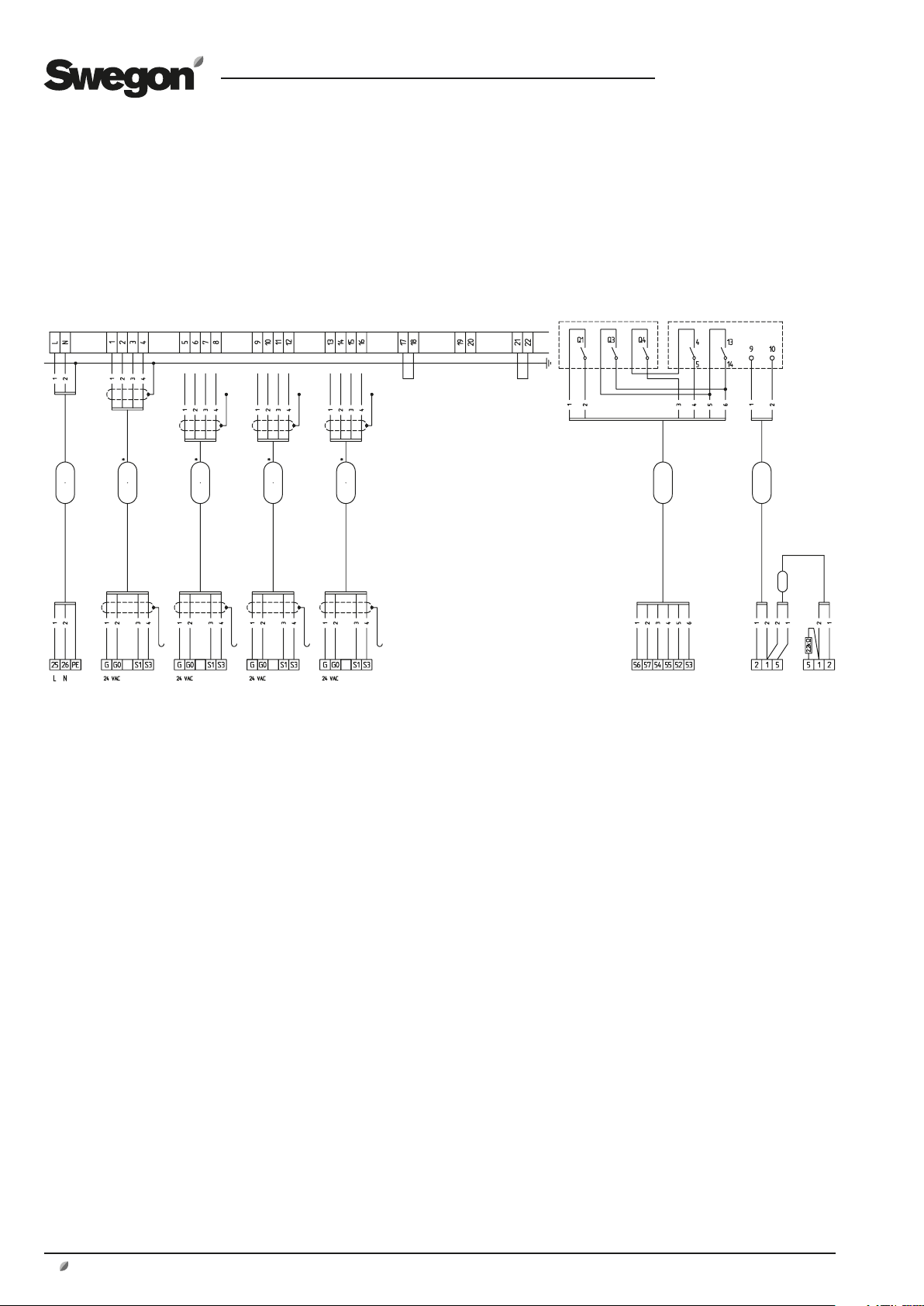
7. Electrical Connections.
The electrical connections are to be wired by a qualified
electrician in accordance with local electrical safety regulations.
7.1 GOLD RX/PX/CX/SD
Terminals in the control box Logic module K7 Control unit B6
GOLD
Unit
MG7:
Damper
actuator
(Section 1)
MG7:
Damper
actuator
(Section 2)
MG7:
Damper
actuator
(Section 3)
MG7:
Damper
actuator
(Section 4)
Controls from
the central fire
alarm, if re-
quired (remove
the jumper
when wiring
connections)
External
Control –
Exercising
Remove
the jumper
if an
electric air
heater is in
operation
(post cool-
ing)
GOLD
Unit
B7:
Smoke
detector
B7:
Smoke
detector
If several damper actuators for smoke are installed in each
alarm section, they must be connected in parallel in a
terminal box.
The end position contact senses when the damper actuator is de-energised, in this position it should be connected
as normally open.
If smoke damper actuators are divided up in sections (various fire compartments), remove the jumper between the
contacts of each section concerned to enable the indication of separate alarms.
* Shielded cables are recommended for installation to
eliminate the risk of inductance occurring between parallel
wires.
If additional smoke detectors are used, they must be connected in series. (Install termination resistor on the last
smoke detector.)
2
www.swegon.com
Continuous product development may give rise to specification changes without notice.
Function:
If in-duct Smoke detector B7 trips, an alarm is transmitted
to the external fire alarm input in the AHU. Damper actuator MG7 is controlled via Control Unit B6.
If the smoke detector becomes fouled, a service alarm is
initiated in Control unit B6 and is transmitted to the AHU
via the external Alarm 2 input.
Alarms can be reset on Control unit B6 or in the Handheld micro terminal P1.
Damper exercising:
The exercising cycle is activated at regular time intervals in
Logic unit K7 or via signals from an external source transmitted to Logic unit K7.
The AHU stops and the dampers are exercised.
If the damper exercising procedure is not satisfactory, an
alarm is indicated on Logic module K7 and the AHU will
not restart. The alarm is transmitted to the AHU via External alarm 2.
Alarms can be reset on Control unit B6 or in the Handheld micro terminal P1.
GB.TBLZ2482.120904
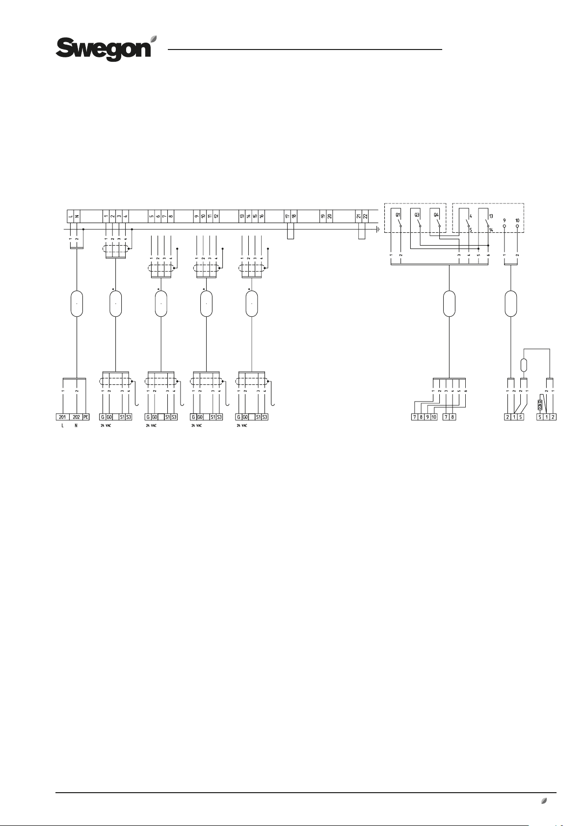
7.2 GOLD LP/COMPACT
Terminals in the control box Logic module K7 Control unit B6
Controls from
the central fire
alarm, if re-
quired (remove
the jumper
when wiring
connections)
GOLD LP/
COMPACT
Unit
MG7:
Damper
actuator
(Section 1)
MG7:
Damper
actuator
(Section 2)
MG7:
Damper
actuator
(Section 3)
MG7:
Damper
actuator
(Section 4)
If several damper actuators for smoke are installed in each
alarm section, they must be connected in parallel in a
terminal box.
The end position contact senses when the damper actuator is de-energised, in this position it should be connected
as normally open.
If smoke damper actuators are divided up in sections (various fire compartments), remove the jumper between the
contacts of each section concerned to enable the indication of separate alarms.
* Shielded cables are recommended for installation to
eliminate the risk of inductance occurring between parallel
wires.
If additional smoke detectors are used, they must be connected in series. (Install termination resistor on the last
smoke detector.)
External
Control –
Exercising
1) The function external stop is
selected in the handheld terminal.
2) The function external alarm is
selected in the handheld terminal.
3) The function external fire/smoke
function is selected in the handheld terminal.
For settings, see the
installation and
maintenance instruction.
Is suitably to be placed on the DIN rail
in the control equipment for GOLD
connected via modular contact to the
The function selection switch are to
Remove
the jumper
if an
electric air
heater is in
operation
(post cool-
ing)
1) 2) 3)
IQnomic Plus module
TBIQ-2-1-aa
LP/COMPACT. For communication
and power supply, the module is
AHU control equipment.
be set in position 0.
GOLD LP/
COMPACT
Unit
B7:
Smoke
detector
B7:
Smoke
detector
Function:
If in-duct Smoke detector B7 trips, an alarm is transmitted
to the external fire alarm input in the AHU. Damper actuator MG7 is controlled via Control Unit B6.
If the smoke detector becomes fouled, a service alarm is
initiated in Control unit B6 and is transmitted to the AHU
via the external Alarm 2 input.
Alarms can be reset on Control unit B6 or in the Handheld micro terminal P1.
Damper exercising:
The exercising cycle is activated at regular time intervals in
Logic unit K7 or via signals from an external source transmitted to Logic unit K7.
The AHU stops and the dampers are exercised.
If the damper exercising procedure is not satisfactory, an
alarm is indicated on Logic module K7 and the AHU will
not restart. The alarm is transmitted to the AHU via External alarm 2.
Alarms can be reset on Control unit B6 or in the Handheld micro terminal P1.
Continuous product development may give rise to specification changes without notice.
www.swegon.com 3
 Loading...