

Swegon TBLZ-1-81-1, TBLZ-1-81-0 Installation Instructions Manual
GB.TBLZ81.190610
Installation Instructions for the TBLZ-1-81-a Push Button
GOLD/COMPACT
1. General
The push button set consists of momentary push button,
frame and box for surface mounting.
2. Field of application
The pushbutton is used for extended high speed or low
speed operation outside ordinary in-operation periods preset in the air handling unit’s internal timer (switch clock).
The pushbutton can also be used for controlling the air
handling unit when the internal timer is not in use.
3. Operation
The air handling unit is controlled to the appropriate operating mode via impulse from the pushbutton. The time
delay can be set in the air handling unit’s control panel.
Note that it is not possible to control the air handling unit
via the pushbutton to the low speed mode while it is operating in the high speed mode.
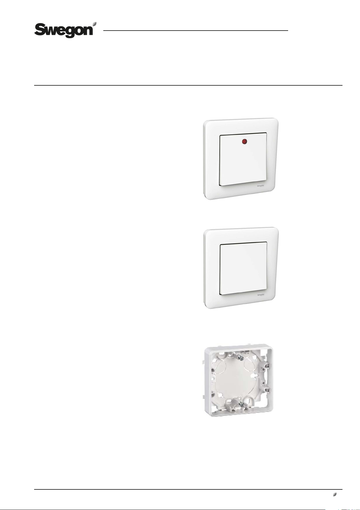
Push button including frame, with indication, TBLZ-1-81-1
4. Installation
For recessed mounting in electrical boxes c-c 60 mm.
The included box is used for surface mounting.
5. Technical data
Enclosure class IP 20
Colour White, nearest RAL 9003
Material Sheet steel, thermoplastic.
Does not contain halogenated
PVC or lead.
Indication Red 24 VAC
Dimensions:
Push button (WxHxD) 71x71x16 mm
Frame (WxHxD) 87x87x12 mm
Box for surface mounting (WxHxD)
85x85x21 mm
Push button including frame, without indication, TBLZ-1-81-0
Box for surface mounting
Specifi cations are subject to alteration without notice.
www.swegon.com 1
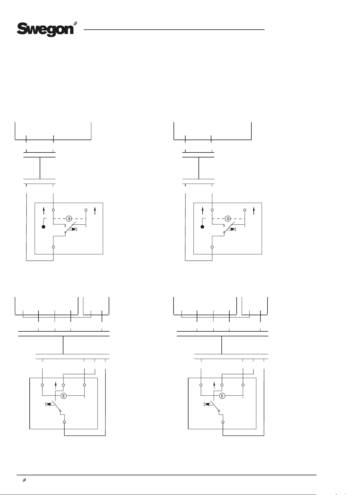
6. Electrical Wiring
The electrical wiring should be carried out by a qualified
electrician in accordance with local regulations.
GOLD RX/PX/CX/SD, version E/F
Low speed High speed
GB.TBLZ81.190610
Terminals on the control circuit card
Terminals on the control circuit card
14 15 16 17
1
1
2
2
LX
X
1
1
TBLZ-1-81-0 TBLZ-1-81-0
High speed with indicationLow speed with indication
Terminals on the control
circuit card
3231 14*14 15 13*
1
3 2
1
H1 H2
4
IQlogic+
23 4
Applicable to size
100/120 GOLD units
only:
If the total load on
Terminals 31-32 is
higher than 16 VA,
use Terminals 201 (G)
and 202 (G0). Terminals 201-202 can be
loaded with a total of
max, 48 VA.
*Terminals on the
I/O module, size 2.
Also see the separate
instruction for the
IQlogic+ module
TBIQ-3.
Terminals on the control
circuit card
3231 14*16 17 13*
1
H1 H2
2
2
LX
3 2
1
X
IQlogic+
4
23 4
Applicable to size
100/120 GOLD units
only:
If the total load on
Terminals 31-32 is
higher than 16 VA,
use Terminals 201 (G)
and 202 (G0). Terminals 201-202 can be
loaded with a total of
max, 48 VA.
*Terminals on the
I/O module, size 2.
Also see the separate
instruction for the
IQlogic+ module
TBIQ-3.
LX
X
TBLZ-1-81-1
Indicating LED lit when the air handling unit
is operating in the low speed mode.
2 www.swegon.com
LX
X
TBLZ-1-81-1
Indicating LED lit when the air handling unit
is operating in the high speed mode.
Specifications are subject to alteration without notice.
 Loading...