

Page 1
TBLZ-1-64 connection kit installation,
GOLD
1. General
The TBLZ-1-64 connection kit is used to connect up to 3
MIRUVENT power roof ventilators or 1 chiller/heat pump
to one GOLD air handling unit. It can also be used as a
cable junction when the application requires more inputs
than those available on the GOLD unit's control circuit
card for COM1-3 and COM6-11 respectively. The connection kit consists of one cable adapter and one bus cable
(0.25 metres).
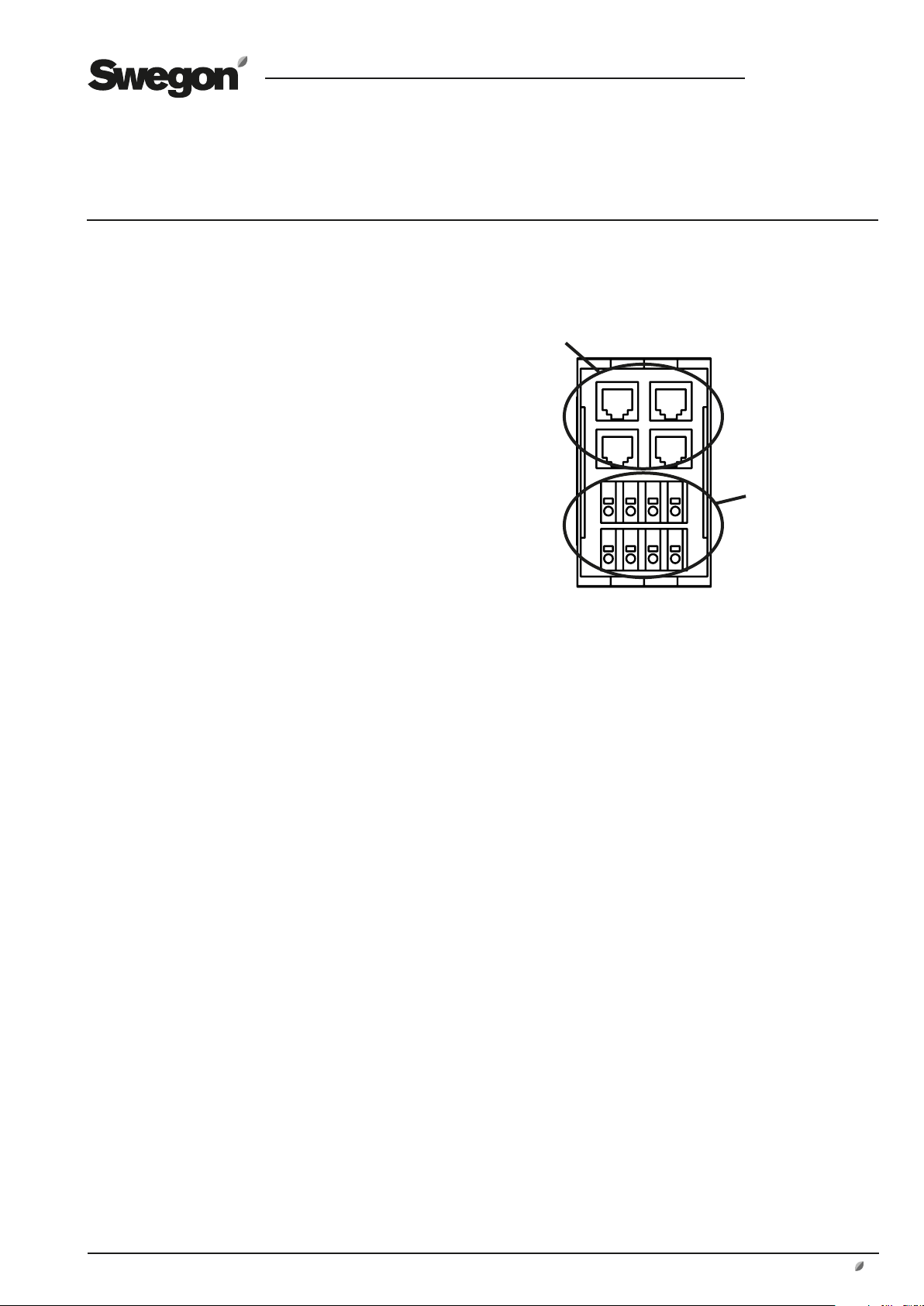
2. Installation
Mount the cable adapter on the DIN rail inside the electric
equipment cubicle of the GOLD air handling unit.
Bus contacts.
GB.TBLZ64.190918
Wiring terminals
Enclosure TBLZ-1-73-1 (accessory) can be used to install
the cable adapter outside of the GOLD air handling unit’s
electrical cabinet.
14
Cable adapter
Swegon reserves the right to alter specifications.
www.swegon.se 1
Page 2

3. Electrical connections
GB.TBLZ64.190918
3.1 Power roof ventilator MIRUVENT
and chiller/heat pump
GOLD, version E/F
Connect the bus cable (supplied) between the bus contact, marked COM4, on the control unit of the GOLD unit
and an optional bus contact on the cable adapter.
Cable adapter
1A2B3
GND4+5-6+7-8+9-
GOLD Control unit
MIRUVENT
Connect the cable between the MIRUVENT motor controller and the cable adapter as shown in the illustration. The
cables are not included in the supply. Twisted pair, shielded cables are recommended.
10+11-12+13
14+15-16+17-18+19
-
SA TempCom 5Com 4Com 3Com 2Com 1
Sensor 1 Sensor 2 Sensor 4Sensor 3 Com 6 Com 7 Com 8 Com 9 Com 10 Com 11
20C21NO22C23NO24C25NO26C27NO28P29G30G031G32
-
Heat Cool
SD
+33-34G35G036Y37U
38 39 40
24V AC In
18V AC In
41 42
WLAN
CPU 2
CPU 1
230V AC Out
230V AC In
45 46
G0
24V AC
4743 44
3.2 Cable junction, GOLD air
handling unit's control circuit card
GOLD, version E/F
If the application requires more inputs than those available
on the COM1-3 and COM6-11 respectively on the GOLD
air handling unit's control circuit card, the cable adapter
can be used as a cable junction.
Connect the bus cable (supplied) between the bus contact, marked COM1-3 and COM6-11 respectively (see the
pertinent installation instructions for the relevant accessory), and an optional bus contact on the cable adapter.
Cable adapter
Up to three
inputs can be
connected to
COM1-3 via
cable adapter.
1A2B3
GND4+5-6+7-8+9-
GOLD Control unit
10+11-12+13
14+15-16+17-18+19
-
SA TempCom 5Com 4Com 3Com 2Com 1
Sensor 1 Sensor 2 Sensor 4Sensor 3 Com 6 Com 7 Com 8 Com 9 Com 10 Com 11
20C21NO22C23NO24C25NO26C27NO28P29G30G031G32
-
Heat Cool
SD
+33-34G35G036Y37U
38 39 40
24V AC In
18V AC In
41 42
WLAN
CPU 2
CPU 1
230V AC Out
230V AC In
45 46
G0
24V AC
Cable adapter
Up to three
inputs can be
connected to
COM6-11 via
cable adapter.
4743 44
Cable adapter
14
4 3 1
U
V
W
PE
U
V
W
PE
BR-
BR+
A
B
Gnd
+10Vdc
0-10Vin
Gnd
Din2
Din1
Dout1
Gnd
MIRUVENT motor controller
BlueBox chiller/heat pump
See the Function Guide for the BlueBox.
3-phase suppply
L1
L1
L2
L2
L3
L3
PE
PE
V+
Adr.Pin1
Bus B
RJ12 Modbus Slave
Bus A
A
Adr.Pin2
Gnd
Adr.Pin1
Bus B
RJ12 Modbus Slave
Bus A
B
Adr.Pin2
Gnd
V+
Gnd
RJ12 Modbus master
Bus B
Bus A
C
e.g. PTH/VOC
V+
Gnd
2 www.swegon.se
Swegon reserves the right to alter specifications.
 Loading...