

SuperWISE II a
SuperWISE II SC a
Instructions for Use
20171120
Ar t. 154522 9
The document was originally written in Swedish.
Symbol key
Symbols on the machine.
This product complies with applicable EU directives
Symbols in this user manual
Warning/Caution!
Electrical voltage
The packaging contains the following
items:
1 SuperWISE II / 1 SuperWISE II SC (Swegon Connect)
1 x Instructions for use
Electrical safety
Permitted voltage, see “Electrical data”.
It is not permissible to insert foreign objects
into the product’s contactor connections or the
electronics's ventilation openings; as this entails
a risk for short circuiting.
Ensure that the product is disconnected from the power
supply when working on products that are not required
to run.
Always follow local/national regulations regarding who
may carry out this type of electrical installation.
Handling
• The product must be handled with care.
Installation
• Moist, cold and aggressive environments must be
avoided.
• Avoid installing the product near a heat source.
• Assemble the product according to applicable industry regulations.
• Install the product so that it cannot be accessed by
unauthorized persons.
• Install the product for easy access during service and
maintenance.
• Install the product so that the cabinet door can open
unobstructed.
• Check to make sure that the product does not have
any visible defects.
• Check that the product is properly secured after it has
been installed.
• Check that all cables are properly secured in place
after they have been installed.
• Avoid installing the product on metal walls or by steel
beams.
Application area
The product is a control unit designed for comfort ventilation within Swegon’s system for demand-controlled ventilation WISE.
The product is used to collect ventilation and climate data
and to optimise the operation of the air handling unit.
SuperWISE also provides data that is available via the web
interface.
SuperWISE SC offers a flexible cloud based service that
permits communications between products, systems and
users. By using Swegon Connect the system can be monitored and controlled remotely.
General
Read through the entire instructions for use
before you install/use the product and save
the instructions for future reference. It is not
permissible to make changes or modify this
product other than what is specified in this
document. Place the cabinet so that it is not
accessible to unauthorised persons.
SuperWISE II / SuperWISE II SC
2
Swegon reserves the right to alter specications. 20171120
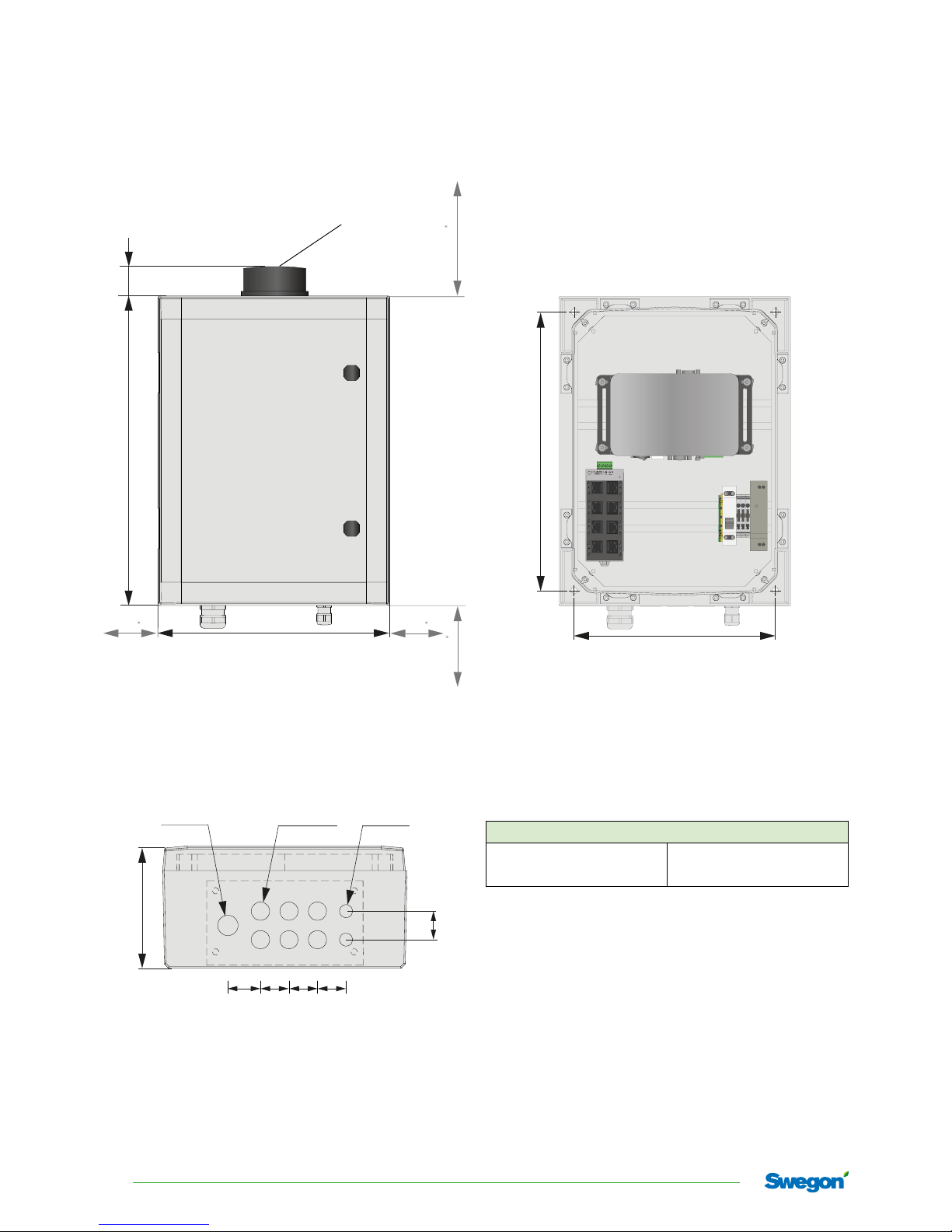
Installation dimensions
and weights
Figure 1. SuperWISE II, SuperWISE // SC, measurement figure.
*
Minimum clearance to adjacent installations.
Figure 2. SuperWISE //, SuperWISE // SC underside, measurement
figure.
150
M25 (x1)
40 3535 35
35
M16 (x2)Ø22,5 (x6)
360
260
Figure 3. Holes for installation, SuperWISE //,
SuperWISE II SC. 4x installation screws (clearance hole Ø = 8
mm), screw selection based on the substrate.
Weight (kg)
SuperWISE II 5.8
SuperWISE II SC 6.3
400
40
300
1
00
Antenna only on SuperWISE II SC
3
20171120 Swegon reserves the right to alter specications.
SuperWISE II / SuperWISE II SC
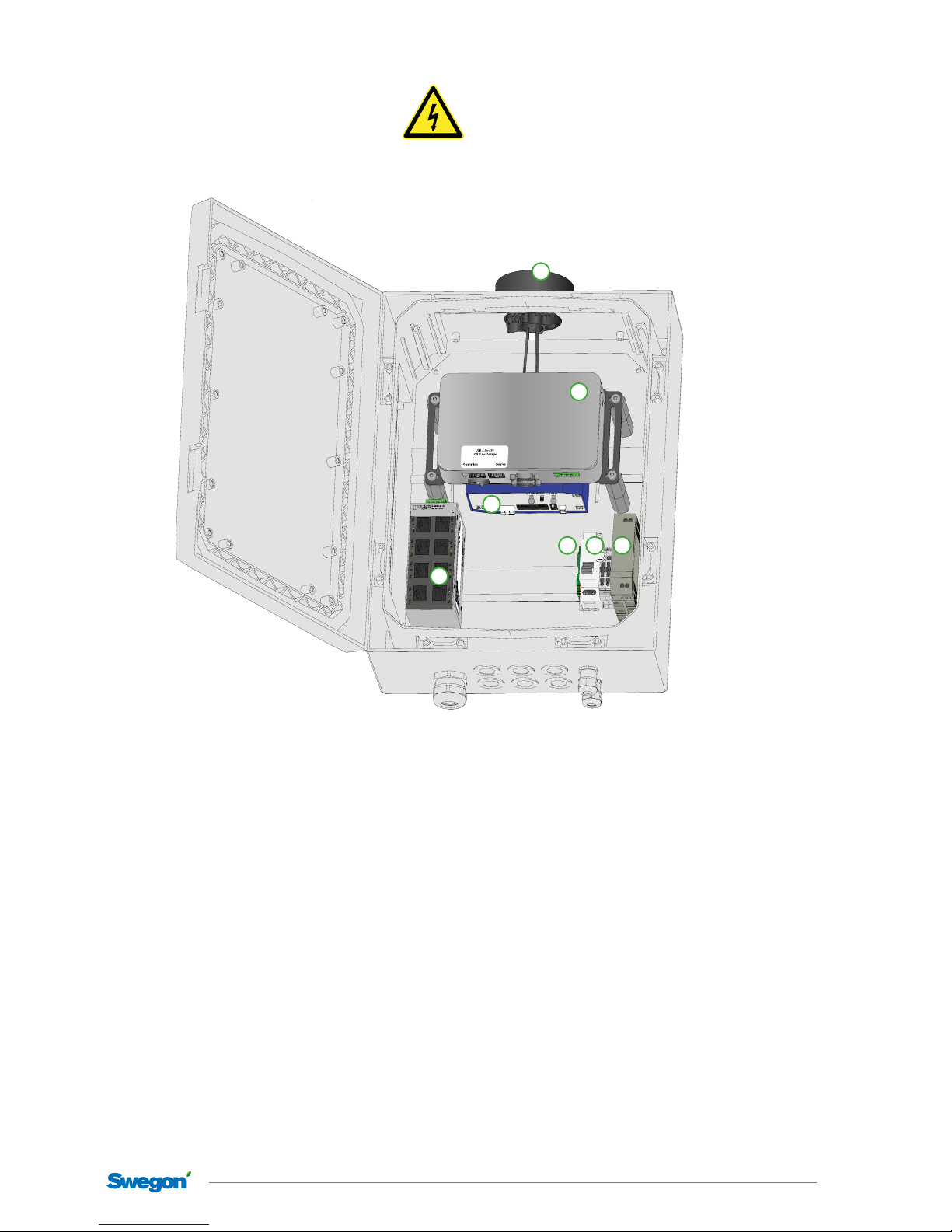
1. SuperWISE II control unit - Main communication unit
2. Swegon Connect – Router (option). Communicates
on the mobile network and ideally on the 4G network. If the cabinet contains Swegon Connect, the
cabinet must be placed so that it can receive mobile
signals. The cabinet can be supplemented with
antenna amplification (6) for improved mobile coverage. See the separate documentation for Swegon
Connect on www.swegon.com
3. Switch - 8 ports (if several ports are required, install a
supplementary switch outside of the cabinet)
• Port 1: SuperWISE II control unit
• Port 2: Swegon Connect
• Port 3-8: Free for e.g. WISE DIR/AHU /BMS
4. Main switch - Connection of the power supply
5. Transformer
6. Antenna to Swegon Connect
7. Earth connection
Figure 4. SuperWISE //, SuperWISE II SC.
NOTE! SuperWISE II does not contain Swegon Connect (2) or an antenna (6).
Connections
Connect the cables in the following order:
A. Communication cables (see item 3 below)
B. Power supply 230 V AC (see items 4 and 7 below)
2
6
1
3
4 57

SuperWISE II / SuperWISE II SC
4
Swegon reserves the right to alter specications. 20171120
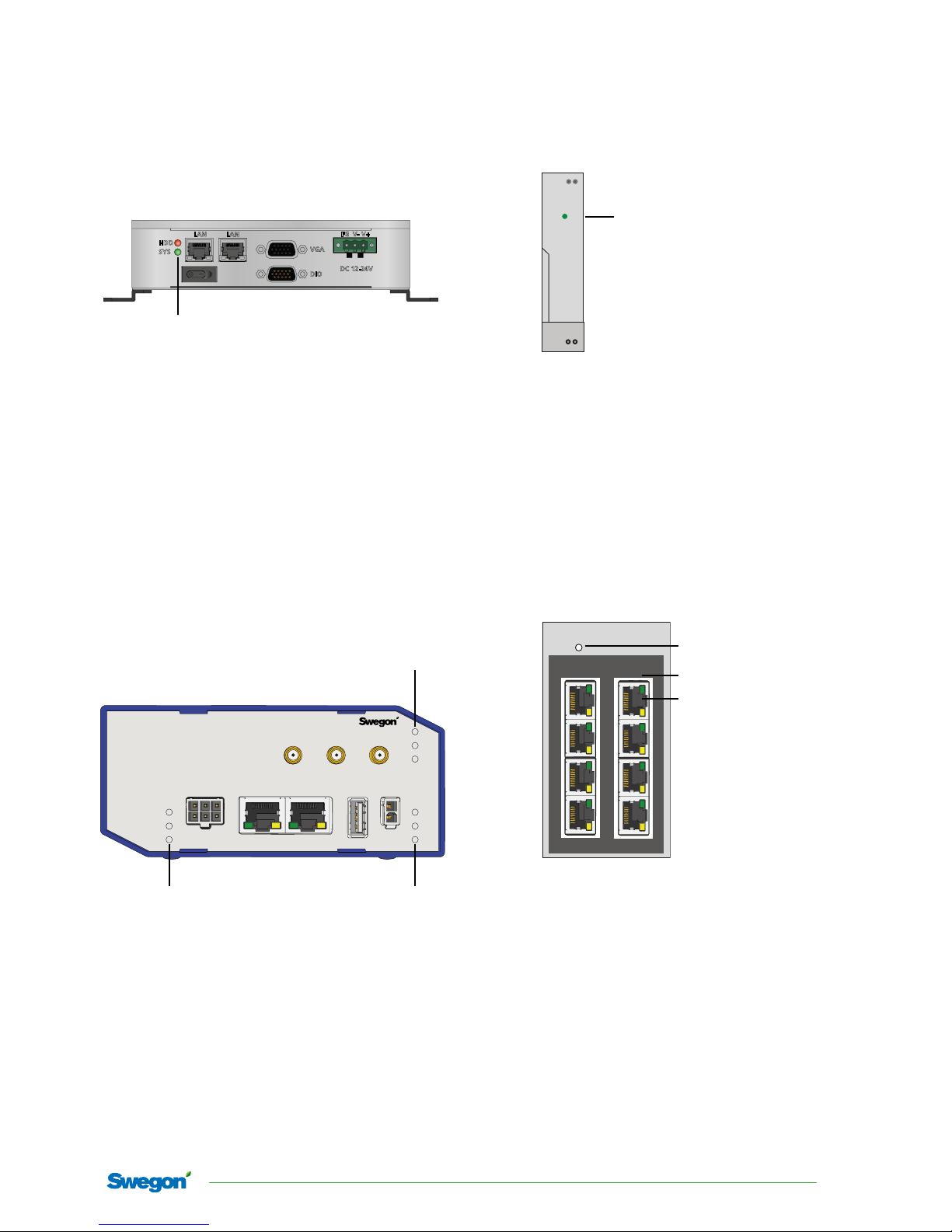
Figure 6. SuperWISE II control unit, top, connection.
COM
USB 3.0
USB 2.0
SIM Card
USB external memory
(Mounted USB memory supplied)
1
3
5
7
2
4
6
8
HDD
SYS
LAN
LAN
VGA
DIO
DC 12-24V
FG V-
V+
DIV GPS ANT
PWRUSBETH0 ETH1
IN0 IN1 OUT
IN0
IN1
OUT
SIM
WAN
DAT
PWR
USR
POE
+
-
Antenna
LN
LN
+
-
Output DC
24V 30W
DC OK
UNI POWER
Input AC
100V-240V
LN
Service
port
Figure 5. SuperWISE //, SuperWISE // SC, connection.
RJ45
RJ45
RJ45
RJ45
Port 3-8 AHU (for example GOLD,
WISE DIR, property network)
230 V AC
L N
5
20171120 Swegon reserves the right to alter specications.
SuperWISE II / SuperWISE II SC
LED - Explanation
DIV GPS ANT
PWRUSBETH0 ETH1
IN0 IN1 OUT
IN0
IN1
OUT
SIM
WAN
DAT
PWR
USR
POE
+
-
Not used.
SIM: Steady green light with the SIM card
is inserted
WAN: Flashes orange if there is contact with
the mobile network (2G, 3G or 4G)
DAT: Flashes red when data is ready to
send over the mobile network
PWR:
(Power)
Flashes green - power to the unit
USR: “Spare”
POE: Power over Ethernet, “Spare”
Swegon Connect
SuperWISE II control unit
HDD
SYS
LAN
LAN
VGA
DIO
DC 12-24V
FG V-
V+
DC power supply
+
-
Output DC
24V 30W
DC OK
UNI POWER
Input AC
100V-240V
LN
Green light when the voltage is on, goes
out when the output voltage drops below
21.5V DC
Switch
1
3
5
7
2
4
6
8
Green light - data being sent
Orange diode denotes which
communication rate is active
Lit: 100 Mbps
Not lit: 10 Mbps
Green light - power to the unit
Figure 7. LED key SuperWISE II control unit.
Figure 8. LED key Swegon Connect control unit.
Figure 9. LED key DC power supply.
Figure 10. LED key switch.
HDD: Flashes red - Storage on the memory unit
SYS: Green light - Power to the unit

SuperWISE II / SuperWISE II SC
6
Swegon reserves the right to alter specications. 20171120
Use
Commissioning
Commissioning must be performed by qualified and
trained WISE service engineers.
Trouble shooting
• Check that the cables are connected correctly.
• Make sure that the product is energized, the supply
LED should be lit/flash green.
• Check the LED indications, see “LED key”.
• Check the status on the SuperWISE user interface (web
pages).
• Check that Swegon Connect is connected correctly and
that the SIM card is inserted correctly.
Maintenance
Cleaning of electrical components
• If needed, use a dry cloth to clean the components.
• Never use water, detergent and cleaning solvent or a
vacuum cleaner.
External cleaning
• If necessary use tepid water and a well-wrung cloth.
• Never use solvents.
Service/maintenance
• The product does not require any maintenance, except
for any cleaning when necessary.
• It is not permissible to open or repair electrical compo-
nents.
• If you suspect that the product or a component is
defective, please contact Swegon.
• A defective product or component must be replaced by
an original spare part from Swegon.
Materials and surface treatment
The cabinet is made of polycarbonate (PC), colour code:
RAL 7035 (Industrial grey).
Disposal
Waste must be handled according to local regulations.
Product warranty
The product warranty or service agreement will not be in
effect/will not be extended if: (1) the product is repaired,
modified or changed, unless such repair, modification
or change has been approved by Swegon AB; or (2) the
serial number on the product has been made illegible or
is missing.
7
20171120 Swegon reserves the right to alter specications.
SuperWISE II / SuperWISE II SC
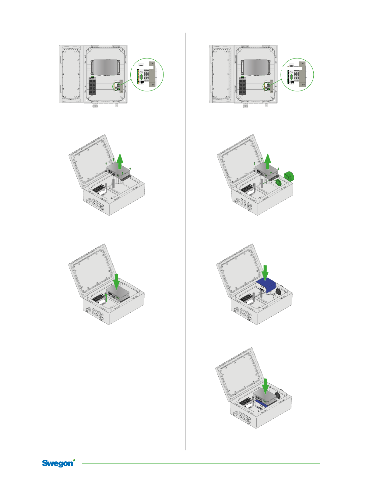
Control unit replacement
Turn off the power using the main switch before any work is
started.
Disconnect all the cables to the control unit, loosen the four
screws and lift out the control unit.
Place the control unit on the 4 spacer bolts and screw back the
screws. Reconnect the cables and switch on the power using the
main power switch.
Figure 11. Control unit replacement.
Retro-fitting Swegon Connect
ON
OFF
Turn off the power using the main switch before any work is
started.
Disconnect all the cables to the control unit, loosen the four
screws and lift out the control unit. Fit the antenna in the top of
the enclosure and tighten the lock nut on the inside.
Antenna
Fit a DIN rail-mount on Swegon Connect and mount on the
DIN rail in the bottom of the cabinet. Connect the antenna and
cables, see “Connection”.
Refit the control unit and connect the cables. Switch on the
power using the main power switch.
Figure 12. Retro-fitting Swegon Connect.
ON
OFF
Main Switch
Main Switch

SuperWISE II / SuperWISE II SC
8
Swegon reserves the right to alter specications. 20171120
References
www.swegon.com
Building Materials Declaration
WISE System Guide
SuperWISE II / SuperWISE II SC product sheet
SuperWISE II / SuperWISE II SC User Manual
Technical data
Output power (ERP) SuperWISE II SC
External mobile network: Max. 2W (GSM mode)
Frequency band SuperWISE II SC
External mobile network: 900/2100... MHz
USB: Type A
Switch/ Ethernet: Switch supports 3 (Gold/AHU)
+ 3 outputs (WISE DIR)
IP class: IP44
Ambient temperature
Operation: -20 – +50°C
Storage: -40 – +80°C
RH: 10-95% non-condensing
CE marking: 2014 / 53 / EU (RED)
2011/65/EU (RoHS2)
Electrical data
Power supply: 230V 10 A
Connections pipe dim.
Power terminals:
Max. 2.5 mm2
Suitable cable diameter through the
chassis (screw terminals):
5-10 mm
Max. power consumption
SuperWISE II: 34W
SuperWISE II SC: 34W
Declaration of Conformity
Swegon AB hereby declares that the radio equipment SuperWISE II / SuperWISE II SC conforms
with the Directive 2014/53/EU and Directive 2011/65/EU.
The complete EU Declaration of Conformity is available at
Swegon’s website: www.swegon.com.
This declaration is applicable only if the product has been
installed according to the instructions in this document and if
no changes have been made on this product.
 Loading...