

Swegon SILVER C RX 100, SILVER C CX 100, SILVER C RX 120, SILVER C CX 120 Installation Instructions Manual
Page 1

Installation instructions for the
SILVER C RX/CX version F, size 100/120
GB.SILVERF120.181005
We reserve the right to alter specifications.
The document was originally written in Swedish.
www.swegon.com 1
Page 2

Contents
1. Installation ............................................... 3
1.1 General .................................................................. 3
1.2 Transport within the site ......................................... 3
1.3 Parts packed together with the unit ........................ 3
1.3.1 Document pocket ............................................. 3
1.4 Arrangement ......................................................... 3
1.5 Method of delivery ................................................. 3
1.5.1 SILVER C RX ...................................................... 3
1.5.2 SILVER C CX ...................................................... 3
1.6 Lifting .................................................................... 4
1.6.1 With a fork-lift truck ......................................... 4
1.6.2 With a crane ..................................................... 4
1.6.2.1 Complete units ............................................ 4
1.6.2.2 Heat exchanger section, supplied split into two
casing sections and rotor (SILVER C RX only) ............. 5
1.7 To assemble the heat exchanger unit section, if
required (SILVER C RX only) .......................................... 7
1.7.1 Alternative 1 ..................................................... 7
1.7.2 Alternative 2 ................................................... 11
1.7.3 Common for Alternatives 1 and 2 ................... 15
1.7.3.1 To adjust the rotor’s inclination ................... 15
1.7.3.2 Sealing plates/purging sector ...................... 16
1.7.3.3 Pressing roller ............................................. 16
1.7.3.4 Vinyl-coated fabric seal .............................. 16
1.7.3.5 Sealing ....................................................... 17
1.8 Version and fan arrangement ............................... 18
1.8.1 SILVER C RX .................................................... 18
1.8.2 SILVER C CX .................................................... 18
1.9 The docking of unit sections ................................. 19
1.9.1 Fan/filter/coil heat exchanger sections
(Coil heat exchanger sections SILVER C CX only) ....... 19
1.9.2 Fastening, front/middle section ....................... 20
1.9.3 Fixation, rear of the unit .................................. 20
1.10 Duct connection ................................................. 21
1.11 Electrical Connections. ....................................... 22
1.12 Installation of pipework package
(SILVER C CX only) ...................................................... 23
GB.SILVERF120.181005
2. Dimensions ............................................23
2.1 SILVER C RX 100/120 ........................................... 23
2.2 SILVER C CX 100/120 ........................................... 24
2 www.swegon.com
We reserve the right to alter specifications.
Page 3
GB.SILVERF120.181005
3440
1070
1. Installation
1.1 General
All staff concerned must acquaint themselves with these
instructions before beginning any work on the unit. Any
damages to the unit or parts of it due to improper handling or misuse by the purchaser or the fitter cannot be
considered subject to guarantee if these instructions have
not been followed correctly.
The product identification label is affixed on the inspection
side of the air handling unit. Refer to the particulars on the
product identification plate when you contact Swegon.
The air handling unit is supplied in packaged condition.
Possible ordered accessories are supplied in separate packaging with the unit.
1.2 Transport within the site
Before removing the transport pallet/transport cradle, if
used, determine whether a forklift truck or a pallet transporter will be used for further transporting the unit within
the site to the spot where it will be installed.
1.3 Parts packed together with the unit
Components such as the commissioning plates, bolts and
document pocket are supplied in separate packaging and
delivered together with the air handling unit.
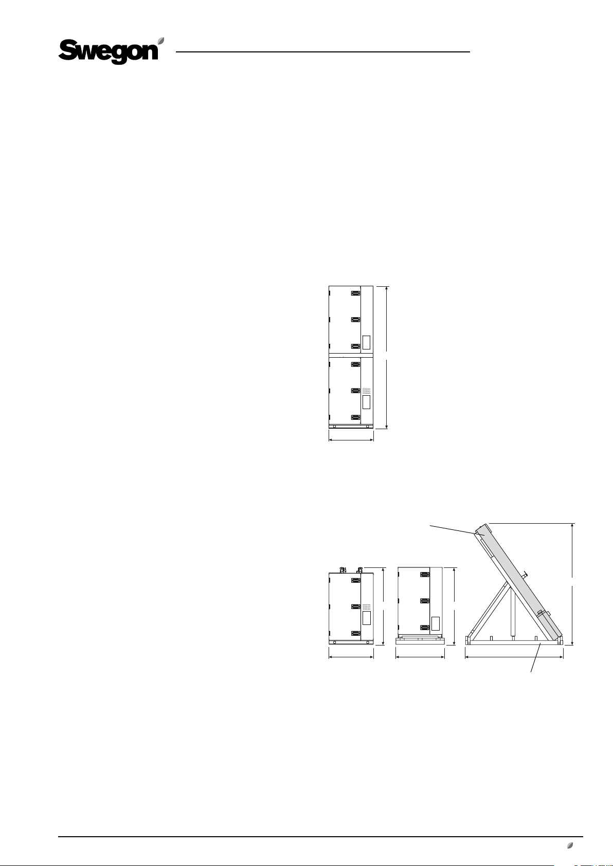
1.5 Method of delivery
1.5.1 SILVER C RX
The SILVER C RX 120 is normally supplied in five separate
sections: Two fan sections, two filter sections and one
heat exchanger section.
The heat exchanger section can also be supplied split into
two casing sections and rotor, in which case the rotor is
supplied tilted in a transport cradle (transport height =
2,930 mm, minimum transport width = 2,350 mm). See
Section 1.7 for installation particulars.
For other dimensions and weights, see Section 2.1.
Heat exchanger section supplied as a separate unit
3440
1070
1.3.1 Document pocket
Secure the document pocket to the exterior of the air
handling unit or another appropriate place.
1.4 Arrangement
The air handling unit must be mounted horizontally on a
flat and firm supporting surface and this surface must be
constructed in a way enabling it to support the weight of
the unit.
When installing the air handling unit and connecting pipework and electric cables, make sure that adequate free
space is provided for opening the inspection doors and
covers and withdrawing functional sections, such as filter
cassettes and fan assemblies, clear of the unit casing.
Inspection space required
A clear space of 1,000 mm should be provided in front of
the unit for opening the inspection doors.
Heat exchanger section, supplied split into two casing sections and rotor
Rotor, Ø 3150
2930
1070
1868
1170 2350
1861
Transport cradle
1.5.2 SILVER C CX
The SILVER C CX 120 is supplied in six separate sections:
Two fan sections, two filter sections and two coil heat
exchanger sections.
For dimensions and weights, see Section 2.2.
We reserve the right to alter specifications.
www.swegon.com 3
Page 4
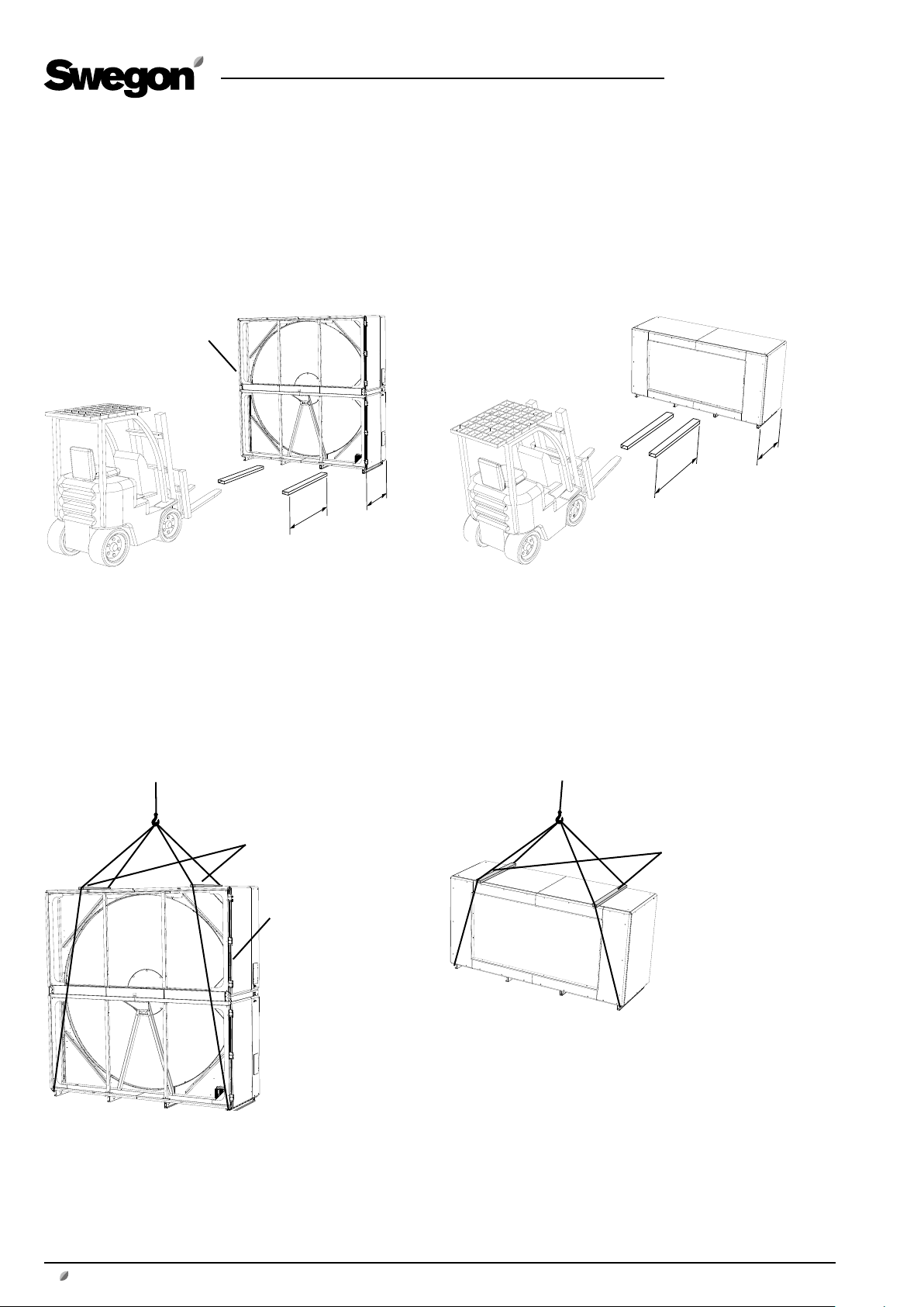
1.6 Lifting
1.6.1 With a fork-lift truck
GB.SILVERF120.181005
NOTE! High centre of
gravity!
1.6.2 With a crane
1.6.2.1 Complete units
Rotary heat exchanger (SILVER C RX only).
L
L
NOTE! Make sure that
forks of the fork-lift truck
are sufficiently long!
Other sections
L
L
NOTE! Make sure that
forks of the fork-lift truck
are sufficiently long!
NOTE! A line spreader must
be used!
NOTE! High centre of
gravity!
Rotary heat exchanger (SILVER C RX only).
4 www.swegon.com
NOTE! A line spreader must
be used!
Other sections
We reserve the right to alter specifications.
Page 5
GB.SILVERF120.181005
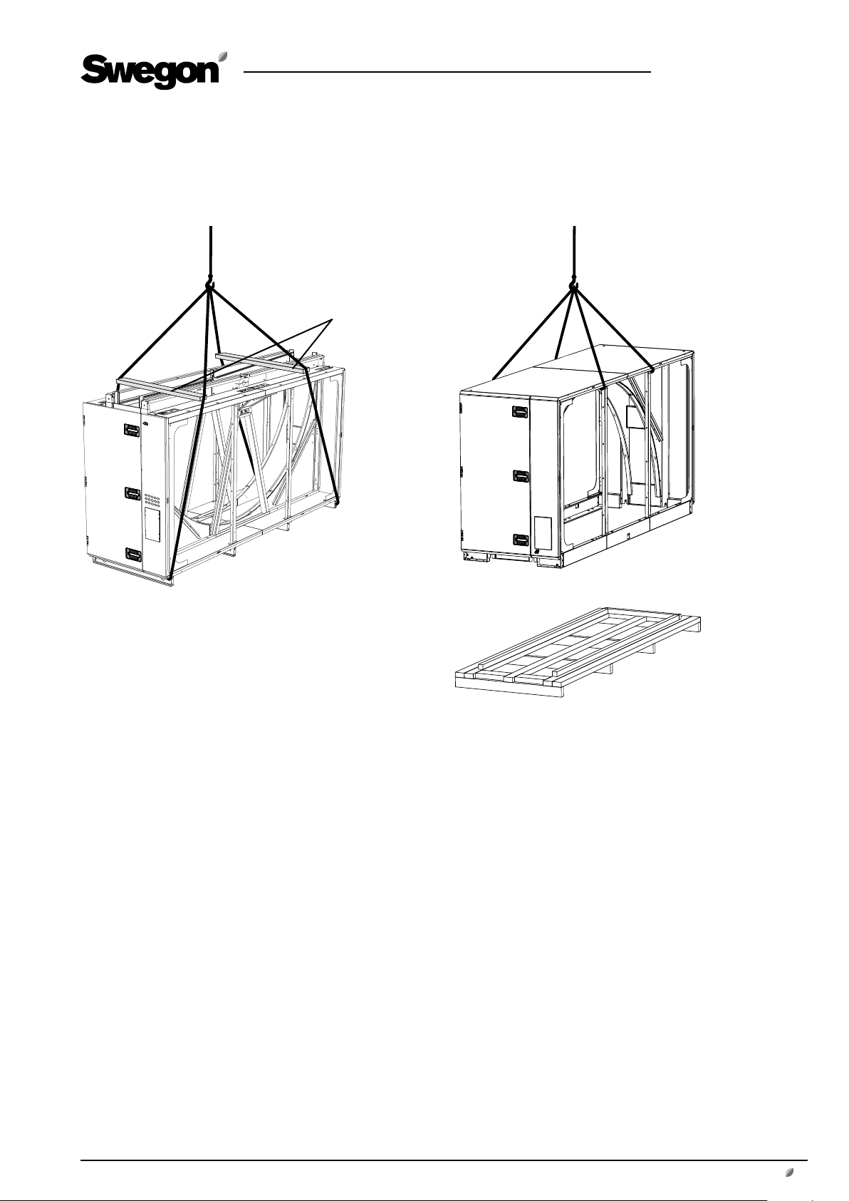
1.6.2.2 Heat exchanger section, supplied split into two casing sections and rotor (SILVER C RX only)
NOTE! A line spreader must
be used!
Lower casing section
Upper casing section
We reserve the right to alter specifications.
www.swegon.com 5
Page 6
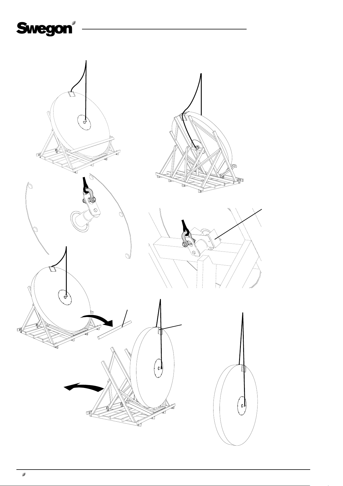
Rotor
GB.SILVERF120.181005
Remove the
wooden stud
Remove the anchor
plate
Guard plate
6 www.swegon.com
NOTE! Carefully raise the rotor so that it
will not be damaged! Make sure that the
lifting device rests against the protecting
plate at the top edge.
We reserve the right to alter specifications.
Page 7
1.7 To assemble the heat exchanger unit
section, if required (SILVER C RX only)
If the heat exchanger unit section is supplied in parts, they
must be jointed together. This can be done in two ways:
Alternative 1 is appropriate for use if there is sufficient free
space upward since this alternative is simpler. If sufficient
space is not available, Alternative 2 should be used.
If the heat exchanger unit section is supplied as one unit,
go on to Section 1.8.
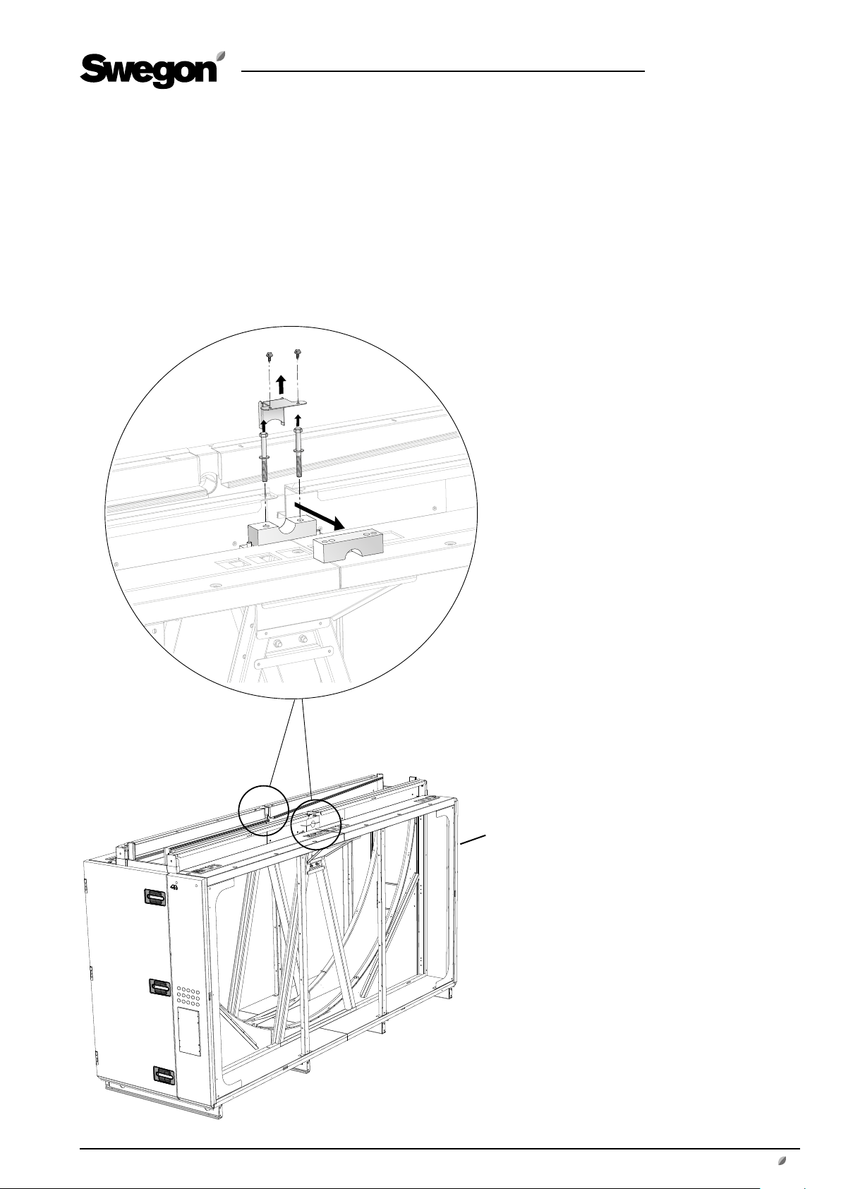
1.7.1 Alternative 1
GB.SILVERF120.181005
Remove the upper shaft bracket
and the sealing plate (2x)
Shaft
mounting
brackets
We reserve the right to alter specifications.
Lower casing section
www.swegon.com 7
Page 8
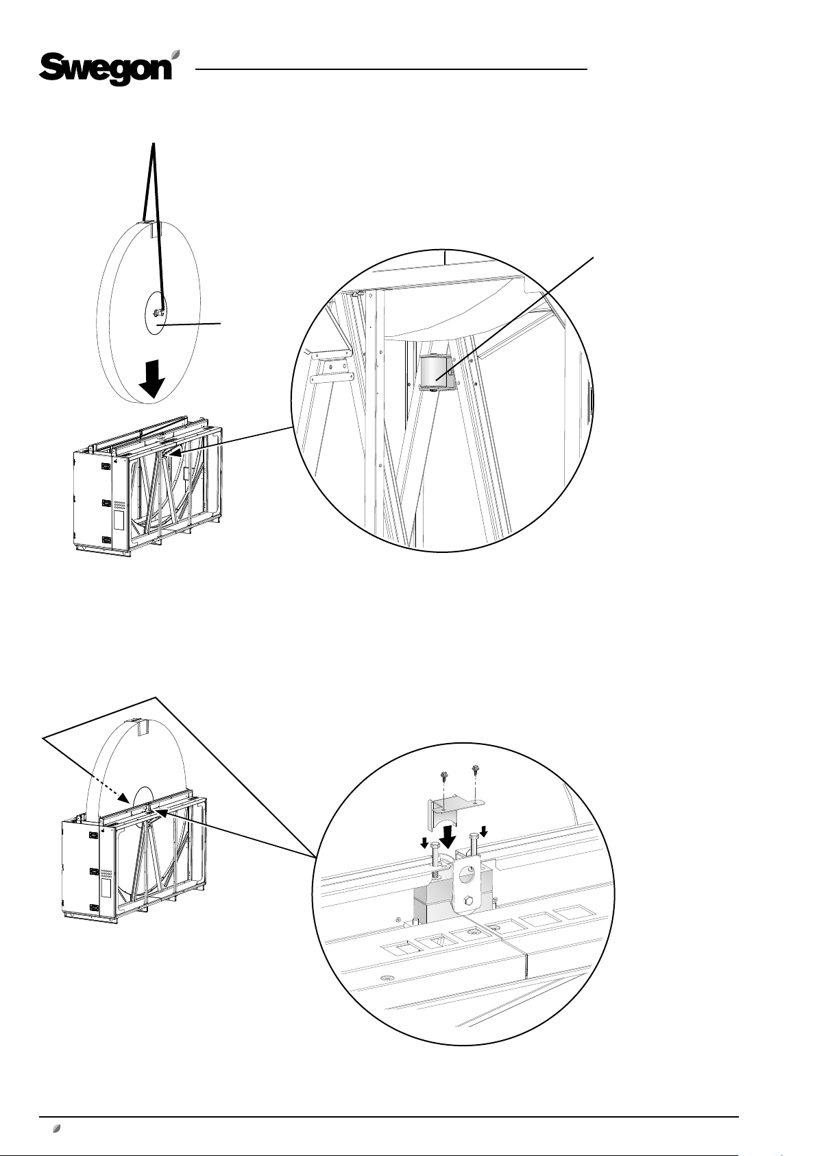
Lift the rotor into the lower casing section (see Section 1.6).
NOTE! IMPORTANT! The smooth side of the rotor hub (without holes) should face the pressing roller!
Be careful not to damage the rotor!
Hub side
GB.SILVERF120.181005
Pressing roller
8 www.swegon.com
Mount the upper shaft bracket
and the sealing plate (2x)
We reserve the right to alter specifications.
Page 9

GB.SILVERF120.181005
Remove the lifting lugs. Refit the bolts
and washers to the shaft end (2x).
Remove the protecting plate
of the rotor.
2 x 4
Lift the upper casing section
onto the lower casing section
(see Section 1.6).
2 x 6
We reserve the right to alter specifications.
Fix the upper casing section to the lower casing
section with the bolts supplied, screwing them
into the pre-fitted rivet nuts (a total of 20 pcs.).
www.swegon.com 9
Page 10

Dismantle the heat exchanger motor +
mounting bracket (6 bolts). Move the motor
+ mounting bracket into position shown in
the illustration and temporarily secure them
with two screws Place the rotor drive belt
around the motor belt pulley.
GB.SILVERF120.181005
Slacken off the two screws
holding the motor + mounting bracket. Move the motor +
mounting bracket back to their
original positions. Secure the
motor + mounting bracket with
bolts (6 bolts).
10 www.swegon.com
See also Section 1.7.3 Common for Alternatives 1 and 2
We reserve the right to alter specifications.
Page 11

1.7.2 Alternative 2
GB.SILVERF120.181005
Remove the upper shaft bracket
and the sealing plate (2x)
Dismantle the heat exchanger motor + mounting bracket
(6 bolts). Remove the sealing plate and tube.
Shaft mounting brackets
We reserve the right to alter specifications.
www.swegon.com 11
Page 12

Lift the rotor from the side into the lower casing section (see
Section 1.6).
NOTE! IMPORTANT! The smooth side of the rotor hub (without holes) should face the pressing roller!
Be careful not to damage the rotor!
Pressing roller
Hub side
GB.SILVERF120.181005
12 www.swegon.com
Mount the upper shaft bracket
and the sealing plate (2x)
We reserve the right to alter specifications.
Page 13

Remove the lifting lugs. Refit the bolts
and washers to the shaft end (2x).
GB.SILVERF120.181005
Remove the protecting plate of the
rotor.
Fit the sealing plate and tube.
Move the motor + mounting bracket into position shown in the
illustration and temporarily secure them with two screws Place
the rotor drive belt around the motor belt pulley.
Slacken off the two screws holding the motor +
mounting bracket. Move the motor + mounting bracket to the position shown in the illustration. Secure the
motor + mounting bracket with bolts (6 bolts).
We reserve the right to alter specifications.
www.swegon.com 13
Page 14

Upper casing section
GB.SILVERF120.181005
Remove the cover panel on the rear
side. Remove the sealing plates (2 pcs.).
Lift the upper casing section from the side onto the
lower casing section (see
Section 1.6).
Mount the cover panel and the seal-
ing plates (2 pcs.).
2 x 2
2 x 6
Fix the upper casing section to the lower casing
section with the bolts supplied, screwing them
into the pre-fitted rivet nuts (a total of 16 pcs.).
See also Section 1.7.3 Common for Alternatives 1 and 2
14 www.swegon.com
We reserve the right to alter specifications.
Page 15

1.7.3 Common for Alternatives 1 and 2
L
L
≈ 0,5xL
≈ 0,5xL
1.7.3.1 To adjust the rotor’s inclination
GB.SILVERF120.181005
The illustration shows a suitable rotor inclination setting
for Fan Arrangement 1. The inclination must always be
towards the filter, which means that the inclination for
Fan Arrangement 2 is in the other direction.
The rotor’s inclination may need to be greater in applications that involve high airflows with associated high
pressure.
Slightly back off the locking bolts. Do not dismantle
the shaft bracket.
Adjust the inclination of the rotor by means
of the adjusting bolts. Tighten the adjusting
bolts equally.
When you have adjusted the inclination,
tighten the locking bolts.
We reserve the right to alter specifications.
www.swegon.com 15
Page 16

GB.SILVERF120.181005
1.7.3.2 Sealing plates/purging sector
Back off the screws
for the sealing plates/
purging sector. Arrange
the sealing plates/
purging sector so that
the bristles are against
the rotor. Tighten the
screws.
1.7.3.4 Vinyl-coated fabric seal
1.7.3.3 Pressing roller
Slip the vinyl-coated fabric seal of the rotor (blue) over the rim
all the way around on both sides of the rotor.
Tension the pressing roller against the rotor hub until you no
longer can roll the pressing roller with your hand.
16 www.swegon.com
We reserve the right to alter specifications.
Page 17

1.7.3.5 Sealing
GB.SILVERF120.181005
Apply appropriate sealing compound/putty to
corners by the sealing
plates/purging sector (4
plates).
Apply appropriate sealing compound/
putty to the joints between the upper casing section and the lower casing section
(front and rear).
Apply appropriate sealing compound/
putty around the sealing plate of the
rotor shaft (2 plates).
We reserve the right to alter specifications.
www.swegon.com 17
Page 18

GB.SILVERF120.181005
1.8 Version and fan arrangement
1.8.1 SILVER C RX
The SILVER C RX 120 is delivered in a right-hand or a lefthand version. The arrangement of the functional sections
can be vertically reversed (specify when ordering), see the
illustration below.
For particulars of the delivery configuration and installation of the relevant air handling unit, see the decal on the
lower section of the heat exchanger.
Supply air fan, right, lower level
Right-hand version
Supply air fan, right, upper level
1.8.2 SILVER C CX
The SILVER C CX 120 is supplied in the right-hand or a
left-hand version and with Fan Arrangement 1, 2, 4 or 5,
see the illustrations below.
For particulars of the delivery configuration and installation of the relevant air handling unit, see the decal on the
lower section of the heat exchanger.
NOTE!The supply air fan is marked 1; the extract air fan is
marked 2. These identifying decals are affixed to the inner
wall of the fan sections.
NOTE! If extract air flows through the lower level: The air
handling unit must be raised at least 50 mm (Higher than
the upper edge of the base beams) to provide space for
the water trap. This can be done by mounting adjustable
feet (accessories, a minimum of 24 feet).
Supply air fan, left, upper level Supply air fan, left, lower level
Left-hand version
Fan arrangement 1 Fan arrangement 2
Fan arrangement 5,
supply air – upper level
Fan arrangement 5,
supply air - lower level
Right-hand version
Fan arrangement 1 Fan arrangement 2
Fan arrangement 4,
supply air – upper level
Fan arrangement 4,
supply air - lower level
Left-hand version
18 www.swegon.com
Outdoor air Supply air Extract air Exhaust air
We reserve the right to alter specifications.
Page 19

1.9 The docking of unit sections
The illustrations in Section 1.10 show a SILVER C RX unit with Fan Arrangement 2. The principle is however the same for the other units.
1.9.1 Fan/filter/coil heat exchanger sections (Coil
heat exchanger sections SILVER C CX only)
GB.SILVERF120.181005
Place the fan, filter and possible coil heat exchanger
sections on top of one another, according to the delivery configuration (see Section 1.8). Secure the upper
section to the lower section with the bolts supplied,
screwing them into the pre-fitted rivet nuts (a total of
4 pcs.).
1.9.2 Fastening, front/middle section
Locate the fan/filter sections by the heatexchanger section
according to the delivery configuration (see Section 1.8).
Fix the fan/filter sections at thefront side of the air handling
unit to the heat exchanger section with the bolts supplied,
screwing them into the prefitted rivet nuts (a total of 2x4 pcs.).
Secure the fan/filter sections to the
heat exchanger section inside the
air handling unit’s middle section
using the supplied screws in the prefitted rivet nuts (total 2x8 pcs.). The
anchoring points inside the unit are
shown in the illustration.
In order to access the anchor points
in the fan section, you must unfasten
the flexible connections and the fan
assemblies and move them outward
toward the inspection door. You can
then tighten the screws from the
opening of the duct connection.
NOTE! You do not need to remove
the fan assemblies completely!
We reserve the right to alter specifications.
www.swegon.com 19
Page 20

1.9.3 Fixation, rear of the unit
Securing with screws at the rear of the air handling unit
can be done in two ways, internally or externally. External
fixing (Alt. 1) is appropriate for use if there is sufficient free
space behind the air handling unit, since this alternative
is simpler. If sufficient space is not available, Alt. 2) can be
used.
Blanking
plate
GB.SILVERF120.181005
Alt. 1
External fixing.
Dismantle the blanking plate and insulation inside the
cover on the rear side of the air handling unit. Secure
the fan/filter sections to the heat exchanger section
with the bolts supplied, screwing them into the prefitted rivet nuts (a total of 2x4 pcs.). Refit the blanking
plate and the insulation.
Alt. 2
Internal installation.
Secure the fan/filter sections to the heat exchanger
section with the bolts supplied, screwing them into
the pre-fitted rivet nuts (a total of 2x4 pcs.). The
anchoring points inside the unit are shown in the illustration.
In order to access the anchor points in the fan section,
you must unfasten the flexible connections and the
fan assemblies and move them outward toward the
inspection door. You can then tighten the screws from
the opening of the duct connection.
N.B.! You do not need to remove the fan assemblies
completely!
20 www.swegon.com
We reserve the right to alter specifications.
Page 21

1.10 Duct connection
The air handling unit’s connection frames are rectangular
and can be jointed to ducts by means of slip-clamps.
The ducts should be insulated according to local regulations and customary trade standards.
GB.SILVERF120.181005
We reserve the right to alter specifications.
www.swegon.com 21
Page 22

1.11 Electrical Connections.
The electrical connections should be wired by a qualified
electrician in accordance with local electrical safety regulations.
See the separate instructions for electrical connections of
the fan motors, heat exchanger control system, actuators,
etc.
1.12 Installation of pipework package
(SILVER C CX only)
For details on how to install the pipework package, see
separate instructions for the TBXZ-42 pipework package.
GB.SILVERF120.181005
22 www.swegon.com
We reserve the right to alter specifications.
Page 23

2. Dimensions
2.1 SILVER C RX 100/120
GB.SILVERF120.181005
M
56
56*
NO
P
P
45
77 3186 77
1048
1000 1048122
N
* The air handling unit is supplied without end connection panel if a duct accessory housed in an insulated
casing will be connected. The AHU can also be supplied with full face end connection panel (accessory).
Size A B D E F G H I J K L M N O P Weight, kg
100 1126 3340 1070 191 1200 2400 3440 520 210 470 3322 800 420 2500 1720 3333-3761
120 112 6 3340 1070 191 120 0 2400 3440 520 210 470 3322 800 420 2500 17 20 3533-3979
Individual weights
Filter section
SILVER C 100/120: 402-540 kg/section.
Fan section
SILVER C 100: 644-720 kg/section.
SILVER C 120: 744-829kg/section.
Heat exchanger section, mounted
SILVER C 100/120: 1241 kg.
Heat exchanger section,
supplied in two casing sections + rotor
Lower casing section = 513 kg
Upper casing section = 300 kg
Rotor = 428 kg
Transport cradle = 190 kg
We reserve the right to alter specifications.
www.swegon.com 23
Page 24

56*
M
P
P
NO
N
200B**
56
77 3186 77
1048
1000 1048122
45
2.2 SILVER C CX 100/120
GB.SILVERF120.181005
* If the duct accessory is housed in an insulated casing, the AHU is supplied without the end connection panel.
The AHU can also be supplied with full face end connection panel (accessory).
** Width of centre section's casing = B + 200 mm.
Size A B D E F G H I J K L M N O P Weight, kg
100 1126 3340 1070 19 0 1200 2400 3440 520 210 470 3322 800 420 2500 1720 4294-4772
120 112 6 3340 1070 190 120 0 2400 3440 520 210 470 3322 800 420 2500 17 20 4494- 4990
Individual weights
Filter section
SILVER C 100/120: 402-540 kg/section.
Fan section
SILVER C 100: 644-720 kg/section.
SILVER C 120: 744-829 kg/section.
Heat exchanger section
SILVER C 100/120: 110 1-112 6 kg / s ec t ion.
24 www.swegon.com
We reserve the right to alter specifications.
 Loading...