

Page 1

Guide to the GOLD version F functions,
Reversible heat pump, RX/HC
GB.FUNKRXHC.180907
1. General
RX/HC is a complete reversible heat pump, fully integrated
in the GOLD air handling unit.
There are three options to defrost the coils
in the exhaust air:
Option 1. Reversing the media circuit.
Option 2. Reversing the media circuit +
electric air heater
Option 3. Reversing the media circuit +
air recirculation section RX/HC
1.1 Installation
See the separate installation and maintenance instructions
to install RX/HC.
See the separate installation instructions to install the air
recirculation section RX/HC, if used.
2. Material specification
Air handling unit with integrated
reversible heat pump GOLD RX/HC
For defrosting according to option 2 (see section 1):
Electric air heater for defrosting. Installed in GOLD RX/HC
from the factory.
For defrosting according to option 3 (see section 1):
Air recirculation section RX/HC for defrosting.
We reserve the right to alter specifications.
www.swegon.com 1
Page 2
3. Function
3
25%%%
25%
100 %
100 %
%1
3.1 General
RX/HC has a reversible heat pump function that is controlled by the GOLD air handling unit’s control system
IQlogic via bus communication to the refrigerant circuit’s
control system iPro.
Operation and setting occurs via the GOLD air handling
unit’s hand-held micro terminal (see section 5. Settings).
The reversible heat pump circuit is controlled
with three signals:
• Stop/Start (0/1)
• Heating/Cooling (0/1)
• Speed level compressor in per cent (25-100%)
When operation is requested, a start signal is sent for the
production of heating or cooling.
Depending on the need in question, a signal is also sent
for the operating level, 25-100%. When operation is
not required, a stop signal is sent and 0 % signal for the
operating level.
3.2 Start of RX/HC air handling units
Start of the reversible heat pump occurs after the GOLD
air handling unit’s ordinary start sequence. Operation of
RX/HC is blocked during the GOLD air handling unit’s
ordinary start sequence.
GB.FUNKRXHC.180907
3.4 Temperature regulation
The heat pump has its own control sequence (HC) in the
GOLD air handling unit’s temperature sequence. The
sequence regulates the temperature requirement 0-100%,
for the heating and cooling sequence respectively.
The heat pump is enabled when the temperature requirement exceeds 3% for 60 seconds and is disabled when
the temperature requirement drops below 1% for 60
seconds (applies for Operating mode - Standard).
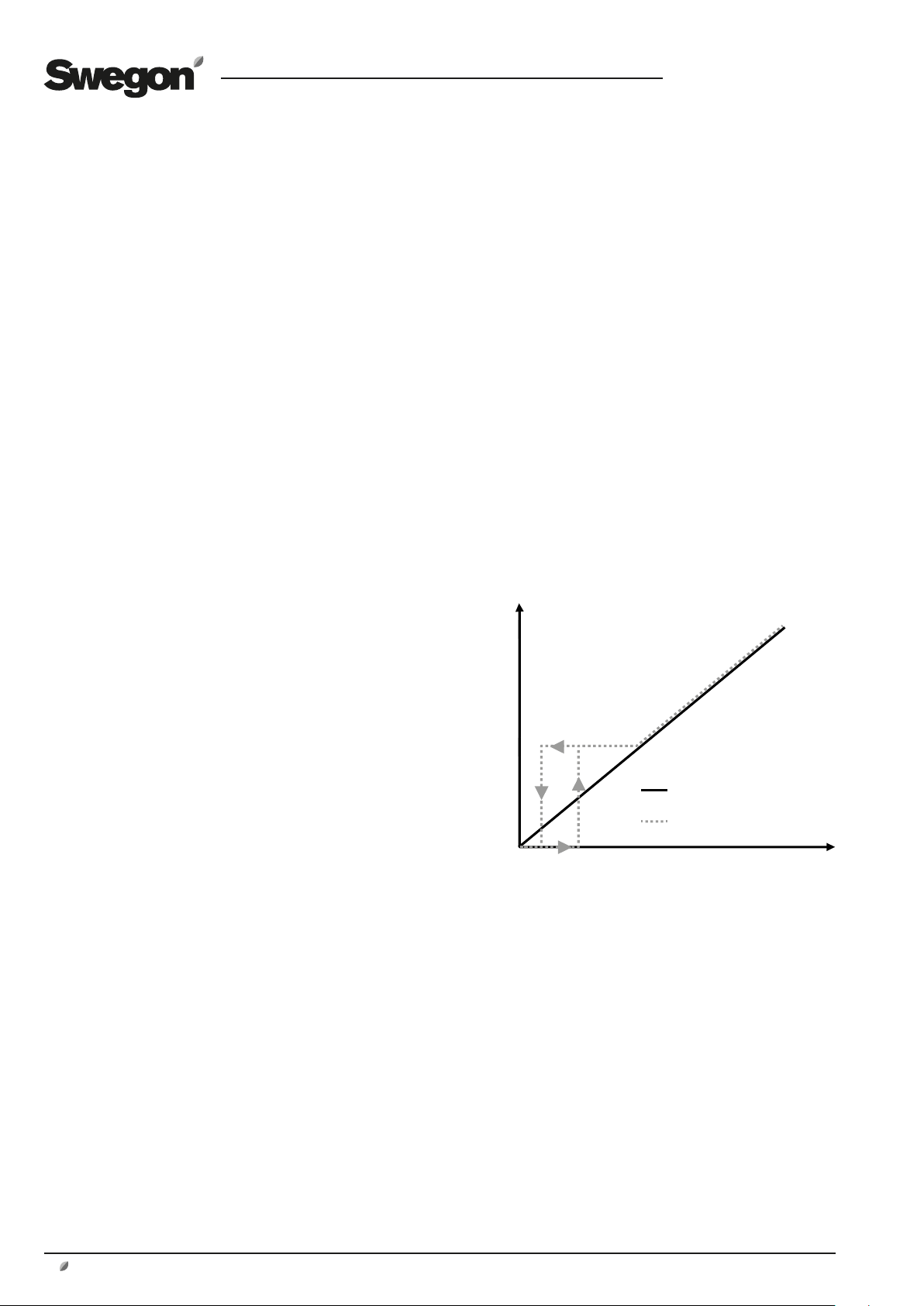
Size 011 - 035 (one compressor)
The refrigerant circuit contains a speed controlled compressor.
The compressor works between a MIN level (normal 25%)
and maximum speed.
At a temperature requirement below 25% the compressor
is run at 25% of max, at a need above 25% the compressor follows the temperature requirement. (see the diagram
below)
3.3 Stop of RX/HC air handling unit
When stopping the GOLD air handling unit, operation of
the reversible heat pump is shut down immediately.
Post-cooling of the refrigerant circuit and electric air
heater for defrosting (if fitted) is carried out. After cooling
is in progress two minutes after the last operation of the
compressor or electric air heater.
Compressor operation
Temperature requirement, GOLD
Operation level, HC
Temperature requirement
2 www.swegon.com
We reserve the right to alter specifications.
Page 3

Size 040 - 080 (two compressors)
0
20
100 % 908070605040302010
0
40
60
80
100%
100
100
0
20
100 % 908070605040302010
0
40
60
80
100%
0
20
100 % 908070605040302010
0
40
60
80
100%
100
The refrigerant circuit contains a speed controlled compressor and a compressor of the on/off type.
The speed controlled compressor works between a MIN
level (total 12.5% per compressor, corresponding to 25%
of the speed controlled compressor) and maximum speed.
Increasing temperature requirement
At a temperature requirement below 12.5% the speed
controlled compressor is run at 25% of max, speed.
GB.FUNKRXHC.180907
Compressor speed controlled
When the temperature requirement increases above
12.5%, the speed controlled compressor is regulated to
follow the temperature requirement.
At a temperature requirement above 50%, the speed
controlled compressor runs to max, speed.
When the temperature requirement increases above
62.5%, the on/off compressor and the speed controlled
compressor are regulated to follow the temperature requirement.
%
80
60
40
20
Compressor operation
0
0
100 % 908070605040302010
Temperature requirement
At a temperature requirement of 100%, both compressors
run at max, speed.
Decreasing temperature requirement
When the temperature requirement decreases below
100%, the on/off compressor is operational and the speed
controlled compressor is regulated to follow the temperature requirement.
At a temperature requirement below 62.5% the speed
controlled compressor is run at 25% of max, speed and
the on/off compressor is operational.
When the temperature requirement decreases below
50%, the on/off compressor shuts down and the speed
Compressor, on/off
%
80
60
40
20
Compressor operation
0
0
100 % 908070605040302010
Temperature requirement
controlled compressor is regulated to follow the temperature requirement.
At a temperature requirement below 12.5% the speed
controlled compressor runs at 25% of max, speed.
Total output
The diagram shows the total capacity in per cent, which is
the same as the control signal from the control system.
We reserve the right to alter specifications.
Total output
%
80
60
60
40
Total output
20
0
0
Temp. requirement, GOLD
Operation level, HC
100 % 908070605040302010
Temperature requirement
www.swegon.com 3
Page 4

GB.FUNKRXHC.180907
3.5 Stabilization
In certain circumstances, there is a need to stabilise operation of the refrigerant circuit and the temperature control
for GOLD.
During stabilization, operation of the refrigeration circuit
is forced to be between MIN-100% of the compressor
speed, regardless of the temperature control requirement.
The stabilisation time is normally 4 minutes + any time
between sending the start request of the refrigeration
circuit and the actual start of compressor operations. If the
cooling circuit is (or recently been in) in operating mode
Adapted operations, the stabilisation time is extended to 8
minutes.
Stabilization starts when one of the following occurs:
• The refrigerant circuit starts in stopped mode
• Defrosting is complete
• Oil return is terminated
• The number of compressors in operation is changed
(except when the number changes from one to zero).
Operations return to normal mode after stabilization is
complete and is controlled between MIN-100% according
to section 3.4 Temperature control.
Stabilization stops when one of the following occurs:
• Stop of the GOLD air handing unit
• Defrosting requirement occurs (see section 3.9)
• Oil return starts (see section 3.8)
3.6 Comfort function
The comfort function is possible to select for heating and/
or the cooling function.
When there is a need of low cooling/heating capacities,
the lowest compressor speed will be too high, the function prioritises comfort before economy.
If the comfort function is selected and the temperature
requirement is low (the corresponding compressor operation is lower than MIN level), comfort mode is enabled.
Operation of the reversible heat pump is then locked
to MIN level of the compressor speed. The rotary heat
exchanger is allowed to regulate to maintain the required
supply air temperature. If instead the temperature requirement exceeds MIN level, operations return to normal
mode.
If any of the following occurs the comfort function is cancelled and operation of the reversible heat pump stops:
• Stop of the GOLD air handing unit
• Time for comfort mode exceeds 30 minutes (factory
setting, can be set 5 – 30 minutes)
• Airflow limits for the supply air and/or extract air drop
below the permitted minimum limit (factory setting 40%
of the GOLD air handling unit’s maximum flow, can be set
0 – 100%)
• Outdoor temperature limits for heating or cooling function are not met (factory setting, heating -20°C, cooling
+15°C. Can be set, heating -50 – +50°C, cooling 0 –
50°C)
• The supply air temperature deviates from the set point to
such an extent that it is within 1 K from the limit value for
any of the alarms Supply air temperature above/below set
point.
• Reheating attempts to start when operations are in heating mode or reheating attempts to start when operations
are in cooling mode. This means that the rotor’s heating/
cooling capacity is not sufficient to balance the temperature and that there is an active regulation sequence after
the rotor.
3.7 Adapted operations
When the evaporation and condensation temperatures
are in a position outside of the optimal working range, the
speed of the compressor is adapted to attempt to reach
the optimal working range.
This is indicated on the hand-held micro terminal of the
GOLD unit.
3.8 Oil return
If the speed of the compressor has been below 28% for
more than 50 minutes, the speed is increased briefly to
extend the life of the compressor.
This results in a larger delivered supply air capacity than
requested. In order to avoid unnecessary system fluctuations, refrigeration circuit shut-off is prevented (independent of the temperature regulator’s requirement) after the
oil return is completed. This is done by starting the stabilization function.
4 www.swegon.com
We reserve the right to alter specifications.
Page 5

GB.FUNKRXHC.180907
3.9 Defrosting
Freezing occurs when operations are in heating mode and
the temperature across the exhaust coil is below 0 °C.
Depending on the temperature, compressor speed, airflow
as well as moisture content in the extract air and fresh air,
freezing occurs with varying speed and behaviour.
The pressure drop across the exhaust coil is measured
to detect the defrosting requirement or stop ongoing
defrosting. Defrosting starts when the pressure drop
exceeds a specific limit. When the pressure drop falls
below another lower limit defrosting stops.
At defrosting with recirculation, the recirculation damper
have a finishing sequence for protection against freezing.
Phases
Defrosting occurs by reversing the heat pump circuit. The
exhaust coil then works as a condenser (as with the cooling function) and heats.
Start delay
When the pressure drop across the exhaust air coil exceeds
the start limit, for a period longer than 60 seconds,
defrosting starts.
Initiation
When defrosting is detected the Initiation phase starts.
The recirculation damper then opens for recirculation, and
if there is an electric air heater this starts. For recirculation
the signal is sent with a delay of 60 seconds, if there is no
recirculation the signal is sent without a delay.
Pre-defrosting
When the defrosting process starts, a signal is sent to the
heating circuit which lowers the compressor speed and
turns the flow directions through the four-way valve.
Defrosting
The defrosting process continues through ramping up the
compressor speed and running until the control system
requests that defrosting stops or until the maximum
defrosting time has been reached.
When defrosting is completed, the outdoor air damper
and the exhaust air damper open, the recirculation
damper closes and stabilization operations are run.
In order to reduce the risk of freezing, a termination
sequence is started at the same time when the recirculation damper is opened and closed a number of times.
Electrical air heater RX/HC (accessory)
When there is a defrosting requirement, the electric air
heater is enabled immediately.
Overheating protection is installed. Post-cooling is carried out if the air handling unit stops during or just after
defrosting.
Critical defrosting
If the evaporation temperature in the heating circuit drops
below a critical limit, defrosting starts.
If the control system discovers ongoing ordinary defrosting, critical defrosting is adapted to the ordinary defrosting sequence, e.g. recirculation starts.
3.10 Limitations
For operations outside the outdoor temperature limits
and/or below air limits, the reversible heat pump function
stops and the air handling unit acts as a GOLD RX.
Outdoor temperature limit, cooling
Operation of the reversible heat pump in cooling mode
is only permitted at an outdoor temperature above 15°C
(adjustable value).
Outdoor temperature limit, heating
Operation of the reversible heat pump in heating mode
is only permitted at an outdoor temperature above -25°C
(adjustable value).
Air flow limits
Operation of the reversible heat pump is only permitted
when the extract airflow and supply airflow exceed a
minimum airflow limit. Values can be set for the extract air
and supply air.
Runoff
In the last part of the defrosting process, the compressor
speed drops and the flow directions through the four-way
valve are turned back.
Adaptive start and stop
Start and stop of the defrosting process is controlled by
calculations in the control system, which take a number
of different factors into consideration that are measured
continuously.
Adaptation is performed after each defrosting to optimise
the process.
Air recirculation section RX/HC (accessory)
When there is a defrosting requirement, the recirculation damper opens, and the outdoor air damper and the
exhaust air damper close.
Recirculation operation is ensured before defrosting starts.
We reserve the right to alter specifications.
www.swegon.com 5
Page 6

4. Wiring diagram
The following wiring diagram deals with connected components in addition to a standard air handling unit GOLD
RX. For the wiring diagram standard GOLD RX, see the
separate document.
Communication cable between connector COM4 on the air
handling unit’s IQlogic control unit and communication terminals 97, 98, 99 on the iPro cooling circuit control.
GB.FUNKRXHC.180907
1A2B3
GND4+5-6+7-8+9-
10+11-12+13
14+15-16+17-18+19
-
SA Te mpCom 5Com 4Com 3Com 2Com 1
Sensor 1 Sensor 2 Sensor 4Sensor 3 Com 6 Com 7 Com 8 Com 9 Com 10 Com 11
20C21NO22C23NO24C25NO26C27NO28P29G30G031G32
Heat Cool
-
SD
+33-34G35G036Y37U
38 39 40
24V AC In
18V AC In
41 42
WLAN
CPU 2
CPU 1
230V AC Ou t
230V AC In
45 46
G0
24V AC
4743 44
Control card
IQlogic
Communication cable between any connector
COM6-11 on the air handling unit’s
IQlogic control unit and pressure sensor.
Communication cable between connector SENSOR4
on the air handling unit’s IQlogic control unit and
temperature sensor.
Communication cable between connector SENSOR3
on the air handling unit’s IQlogic control unit and
temperature sensor.
97
98
99
-
+
GND
Control card iPro,
cooling circuit
control
Pressure sensor for pressure drop
measurement over the cooling circuit’s
exhaust air coil (function selector
switch in D position).
Temperature sensor for density correction of the airflow. The sensor is
placed between the coil and fan in the
exhaust air/supply air.
Temperature sensor for density correction of the airflow. The sensor is
placed between the coil and fan in the
exhaust air/supply air.
Electric air heater for defrosting (accessory)
Control card
IQlogic
1A2B3
GND4+5-6+7-8+9-
6 www.swegon.com
10+11-12+13
14+15-16+17-18+19
-
SA Te mpCom 5Com 4Com 3Com 2Com 1
Sensor 1 Sensor 2Sensor 4Sensor 3 Com 6 Com 7 Com 8 Com 9 Com 10 Com 11
20C21NO22C23NO24C25NO26C27NO28P29G30G031G32
-
Heat Cool
SD
+33-34G35G036Y37U
38 39 40
24V AC In
Connect from any of connectors COM1 or COM2 on the
IQLogic+module to one of the connectors on the air handling unit's IQLogic control unit marked COM6-11.
G0
24V AC
The function
selector switch
WLAN
CPU 2
CPU 1
18V AC In
230V AC In
230V AC Ou t
41 42
45 46
must be set to
position 5.
4743 44
IQlogic+-module
1234 5678 9101112
++--S - S
-+-+ -
+
IQlogic
COM POWER
D
C
E
B
F
A
0
9
1
8
P1
2
7
3
6
5
4
Com 1Heat/Cool Com 2
+17-
C13NO14C15NO
16
18
+19-
G21G0
20
22
Connect from connector HEAT/COOL on the
+
IQlogic
-module to the
RJ45 connector on the
electric air heater.
Electric air
heater
We reserve the right to alter specifications.
Page 7

GB.FUNKRXHC.180907
5. Electrical connection of the air recirculation section RX/HC (accessory)
The electrical connections are to be wired by a qualified
electrician in accordance with local electrical safety regulations.
Damper
-
actua
tor
The damper motor has a 0.9 metre long connection cable,
4 x 0.75 mm2 and is connected in the junction box, IP54.
IQlogic+
Requisite accessories
Outdoor air damper TBSA-X-xxx-xxx-x-1 or
TCSA-xxx, spring return
Exhaust air damper TBSA-X-xxx-xxx-x-1 or
TCSA-xxx spring return
Exhaust air
28
P
damper
G
30
G0
G0
Outdoor air
damper
G0
G
12
Air recirculation
damper
G0
G
1212 89
32
31
G0
G
U
Y
Function
In normal mode the recirculation damper must be fully
closed (deenergized state).
When defrosting is selected, the air recirculation damper
should be completely open (actuating time: 90 seconds).
1234 5678 9101112
-+-+ -
++--S - S
The IQlogic+ module is placed
in the electrical cabinet on the
GOLD air handling unit.
GOLD Control unit
Communication cable to the control unit of
the air handling unit, where it is connected
to one of the outlets for COM 6-11.
We reserve the right to alter specifications.
IQlogic
D
C
E
B
F
A
0
9
1
8
P1
2
7
3
6
5
4
C13NO14C15NO
16
+
COM POWER
Com 1Heat/Cool Com 2
+19-
+17-
18
The function
selector switch
must be set to
position 5.
G21G0
20
22
www.swegon.com 7
Page 8

6. Settings
For basic details on how to use the hand-held terminal,
see the Operation and Maintenance Instructions for the
GOLD Air Handling Unit.
The functions for the reversible heat pump are activated
manually under Functions/HC. This is only possible for
GOLD RX (rotary heat exchanger).
GB.FUNKRXHC.180907
HC
HC is activated by setting Position HC in On. Other possible settings are shown when HC is activated.
If any of the accessories electric air heater HC or air
recirculation section HC are fi tted, these are activated
by selecting the required accessory from the menu HC
defrosting accessory.
Set the required heating and cooling function, standard or
comfort.
Set the required values for outdoor temperature limits for
heating and cooling.
Set the required values for airfl ow limits for supply air and
extract air.
Calibration is carried out at the factory. If recalibration is
required, this can be carried out by pressing the calibration button. Remaining time is shown when calibration is
in progress. Calibration date and lowest/highest air fl ow/
pressure drop are shown when calibration is performed.
Function
Outdoor temperature limits
Air fl ow limits
Calibration
Regulation sequence for heating and cooling can be set,
see the separate Function manual installation.
8
www.swegon.com
Temperature
Regulation sequence
We reserve the right to alter specifi cations.
 Loading...