

Page 1

GB.BlueBox.180415
Swegon reserves the right to alter specifications.
www.swegon.com 1
GOLD version E/F, Function Guide,
SMART Link/AQUA Link
1. General
The SMART Link function is intended for use in controlling
the times, temperatures, etc. as well as reading the alarms
and settings of a Swegon chiller/heat pump via a handheld micro terminal and web page in a GOLD air handling
unit.
For electrical wiring and functionality at connection with
Nestor, see separate documentation.
1.1 Energy-saving functions
1.1.1 Control of the supply air temperature/supply
flow temperature
By comparing the supply air temperature downstream of
the fan with the supply flow temperature to the coil, the
equipment makes sure that the valve for the coil opens
only if the water has a temperature that conveys energy to
the air.
This means that if there is a heat load and the water temperature is lower than the supply air temperature, which
can occur during defrosting cycles, the valve is not allowed
to open. If there is a cooling load, the reverse applies.
1.1.2 Optimisation function
A cooling unit/heat pump will be more effective if the difference between the outdoor temperature and the water
temperature is as small as possible. This reduces energy
consumption.
The supply air energy to a water coil is controlled by a
valve. Optimisation of the valve position so that it always
strives to be fully open, and instead control the water
temperature, saves energy.
1.1.3 AQUA Link
The AQUA Link provides both air handling units and
comfort modules with cooling power. Even here energy
savings are obtainable by allowing the need to control the
water temperature.
Depending on whatever the specific need is (dehumidification, cooling of the supply air, cooling of the room via
comfort modules), the temperature of the chilled water
can be varied and the control system ensures that the
chiller will not produce chilled water that is colder than
necessary.
1.1 Installation
The installation work is fast and simple compared with
that of other systems. It requires only hydraulic and electric connection between the GOLD unit, chiller/heat pump
and possible AQUA Link.
All the necessary control functions are ready to activate.
One supplier of all the equipment.
The IQlogic
+
module TBIQ-3-1 is included in the AQUA
Link equipment cubical.
2. Material Specification
Air handling unit GOLD RX/PX/CX/SD
Cable adapter TBLZ-1-64
IQlogic
+
module,
extra regulation sequence (SMART link) TBIQ-3-2
Chiller/heat pump manufactured by Swegon that uses
glycolic water as cooling or heating media (not evaporative media).
Other equipment to the extent required:
Set of valves, air heater, air cooler, dual-purpose coil,
AQUA Link.
Page 2
GB.BlueBox.180415
Swegon reserves the right to alter specifications.
2 www.swegon.com
BT1
BT50BT40
MF2
BT30
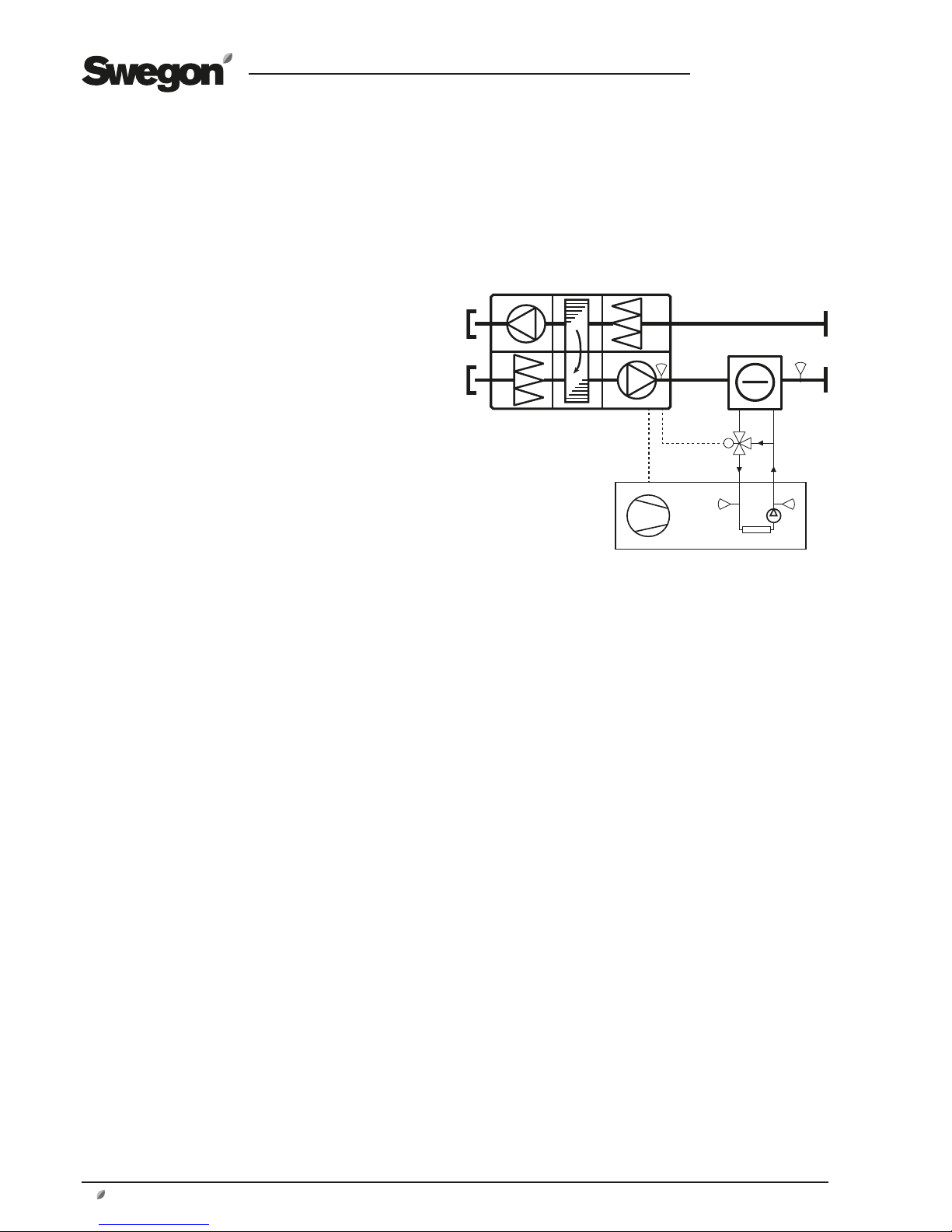
3. Operation
See below and the following pages for diagrammatic
descriptions of the function.
3.1 Control of cooling/heating to the GOLD
via Swegon chiller/heat pump
3.1.1 Chiller
The cooling capacity of the supply air is controlled via an
IQlogic+ module (extra regulation sequence function, see
separate instructions for the TBIQ IQlogic+ module) preset
for cooling (0-10 V). The function can be activated in the
hand-held terminal of the GOLD air handling unit (see the
Operation and Maintenance Instructions for the GOLD).
Communication with the chiller can be activated under
Functions in the hand-held micro terminal of the GOLD
unit. See Section 5.
If temperature sensor BT1 calls for cooling, the function
transmits a refrigerant setpoint (12°C*) to the chiller via
Modbus.
If the temperature by temperature sensor BT50 is lower
than the temperature by temperature sensor BT30**, the
function allows valve MF2 to regulate the flow.
If the temperature by temperature sensor BT50 is higher
than the temperature by temperature sensor BT30**, the
function does not allow valve MF2 to regulate the flow
(forces it to close).
Optimisation function active:
To ensure the best functionality when the optimisation
function is activated, the value for cooling diff. (2 K*)
should be set to the same value as that set in the chiller,
see Section 5.
If the temperature by temperature sensor BT40 (reference
water) is within 2K* from the refrigerant temperature
setpoint and if it has been so during a continuous period
of more than 60 seconds* the optimisation function is
allowed.
If the optimisation function is allowed and valve MF2 is
fully open (100%*) the controller decreases the refrigerant temperature setpoint at a rate of 0.3K/minute*.
If the optimisation function is allowed and valve MF2 is
open less than 80%*, the controller increases the refrigerant temperature setpoint at a rate of 0.6K/minute*.
* Factory setting. The value can be changed.
** Estimated temperature in the GOLD RX.
Modbus
0-10 V
GOLD
Supply
air
Swegon chiller
A pump and accumulator tank can be
added and, depending on the size of
the system, can be located inside or
outside the chiller.
Page 3
GB.BlueBox.180415
Swegon reserves the right to alter specifications.
www.swegon.com 3
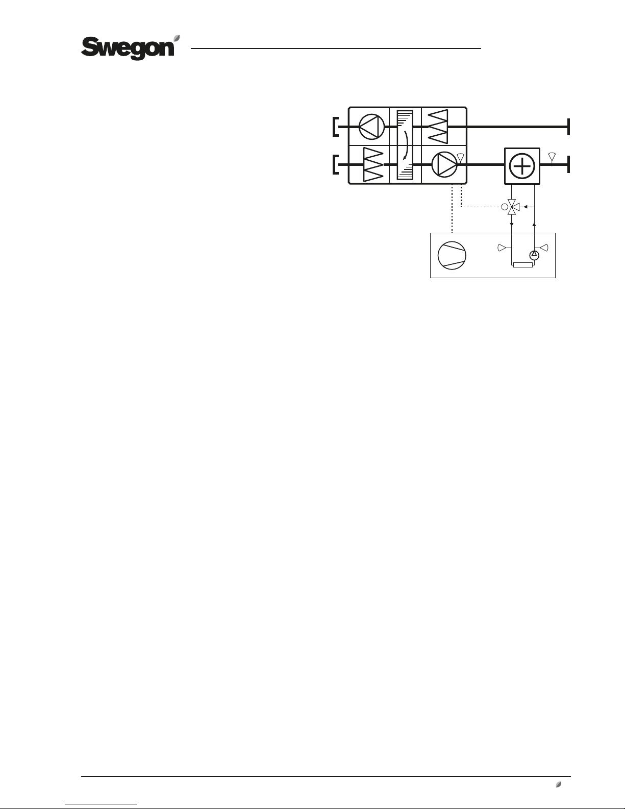
BT1
BT50
MF1
BT30
BT40
Modbus
0-10 V
GOLD
Supply
air
Swegon heat pump
A pump and accumulator tank can be
added and, depending on the size of
the system, can be located inside or
outside the heat pump.
3.1.2 Heat pump
The heating capacity of the supply air is controlled via an
IQlogic+ module (extra regulation sequence function, see
separate instructions for the TBIQ IQlogic+ module) preset
for heating (0-10 V). The function can be activated in the
hand-held terminal of the GOLD air handling unit (see the
Operation and Maintenance Instructions for the GOLD).
Communication with the heat pump can be activated
under Functions in the hand-held micro terminal of the
GOLD unit. See Section 5.
If temperature sensor BT1 calls for heating, the function
transmits a start signal and heating medium setpoint
(40°C*) to the heat pump via Modbus.
If the temperature by temperature sensor BT50 is higher
than the temperature by temperature sensor BT30**, the
function allows valve MF1 to regulate the flow.
If the temperature by temperature sensor BT50 is lower
than the temperature by temperature sensor BT30**, the
function does not allow valve MF1 to regulate the flow
(forces it to close).
Optimisation function active:
To ensure the best functionality when the optimisation
function is activated, the heating diff. value (3 K*) should
be set to the same value as that set in the heat pump. See
Section 5.
If the temperature by temperature sensor BT40 (reference
water) is within 3K* from the heating medium temperature setpoint and if it has been so during a continuous
period of more than 60 seconds* the optimisation function is allowed.
If the optimisation function is allowed and valve MF1 is
fully open (100%*) the controller increases the heating
medium temperature setpoint at a rate of 0.3K/minute*.
If the optimisation function is allowed and valve MF1 is
open less than 80%*, the controller decreases the refrigerant temperature setpoint at a rate of 0.6K/minute*.
* Factory setting. The value can be changed.
** Estimated temperature in the GOLD RX.
Page 4
GB.BlueBox.180415
Swegon reserves the right to alter specifications.
4 www.swegon.com
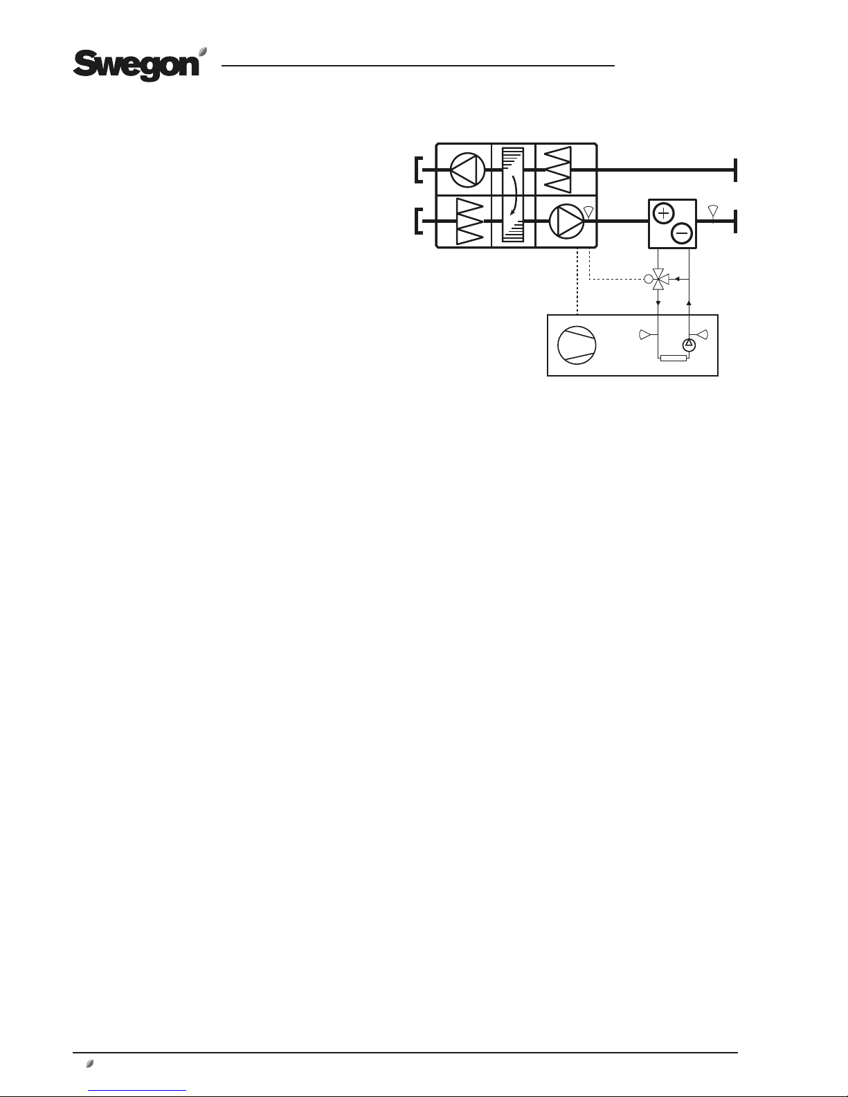
BT1
BT50
BT40
MF1
BT30
3.1.3 Reversible chiller/heat pump
The heating or cooling capacity of the supply air is controlled via an IQlogic+ module (extra regulation sequence
function, see separate instructions for the TBIQ IQlogic+
module) preset for heating and cooling (0-10 V). The
function can be activated in the hand-held terminal of the
GOLD air handling unit (see the Operation and Maintenance Instructions for the GOLD).
Communication with the reversible chiller/heat pump
can be activated under Functions in the hand-held micro
terminal of the GOLD unit. See Section 5.
Cooling
If temperature sensor BT1 calls for cooling, the function
transmits a start signal for cooling and a refrigerant setpoint (12°C*) to the reversible chiller/heat pump via Modbus.
If the temperature by temperature sensor BT50 is lower
than the temperature by temperature sensor BT30**, the
function allows valve MF1 to regulate the flow.
If the temperature by temperature sensor BT50 is higher
than the temperature by temperature sensor BT30**, the
function does not allow valve MF1 to regulate the flow
(forces it to close).
Optimisation function active:
To ensure the best functionality when the optimisation
function is activated, the value for cooling diff. (2 K*)
should be set to the same value as that set in the reversible
chiller/heat pump. See Section 5.
If the temperature by temperature sensor BT40 (reference
water) is within 2K* from the refrigerant temperature
setpoint and if it has been so during a continuous period
of more than 60 seconds* the optimisation function is
allowed.
If the optimisation function is allowed and valve MF1 is
fully open (100%*) the controller decreases the refrigerant temperature setpoint at a rate of 0.3K/minute*.
If the optimisation function is allowed and valve MF1 is
open less than 80%*, the controller increases the refrigerant temperature setpoint at a rate of 0.6K/minute*.
Heating
If temperature sensor BT1 calls for cooling, the function
transmits a start signal for heating and a heating medium
setpoint (40°C*) to the reversible chiller/heat pump via
Modbus.
If the temperature by temperature sensor BT50 is higher
than the temperature by temperature sensor BT30**, the
function allows valve MF1 to regulate the flow.
If the temperature by temperature sensor BT50 is lower
than the temperature by temperature sensor BT30**, the
function does not allow valve MF1 to regulate the flow
(forces it to close).
Modbus
0-10 V
GOLD
Supply
air
Swegon chiller/heat pump
A pump and accumulator tank can be
added and, depending on the size of
the system, can be located inside or
outside the chiller/heat pump. For more
information, see the Swegon product
brochure.
Optimisation function active:
To ensure the best functionality when the optimisation
function is activated, the heating diff. value (3 K*) should
be set to the same value as that set in the reversible
chiller/heat pump. See Section 5.
If the temperature by temperature sensor BT40 (reference
water) is within 3K* from the heating medium temperature setpoint and if it has been so during a continuous
period of more than 60 seconds* the optimisation function is allowed.
If the optimisation function is allowed and valve MF1 is
fully open (100%*) the controller increases the heating
medium temperature setpoint at a rate of 0.3K/minute*.
If the optimisation function is allowed and valve MF1 is
open less than 80%*, the controller decreases the heating
medium temperature setpoint at a rate of 0.6K/minute*.
* Factory setting. The value can be changed.
** Estimated temperature in the GOLD RX.
Page 5
GB.BlueBox.180415
Swegon reserves the right to alter specifications.
www.swegon.com 5
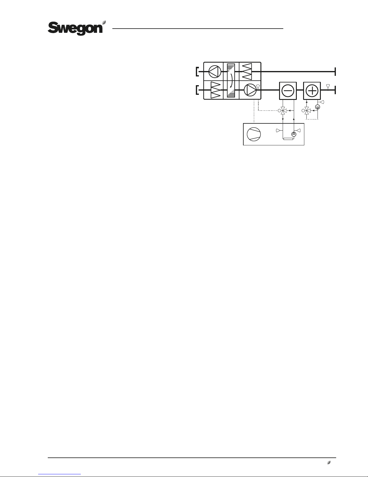
BT1
BT50BT40
MF2
MF1
BT30
3.1.4 Chiller and external heating
The cooling capacity of the supply air is controlled via an
IQlogic+ module (extra regulation sequence function, see
separate instructions for the TBIQ IQlogic+ module) preset
for cooling (0-10 V). The function can be activated in the
hand-held terminal of the GOLD air handling unit (see the
Operation and Maintenance Instructions for the GOLD).
The function controls external heating (waterborne or
electric) via the GOLD unit’s ordinary output for heating (0-10 V). The air heater for heated water has a frost
monitor function and is automatically activated when it is
connected.
Communication with the chiller can be activated under
Functions in the hand-held micro terminal of the GOLD
unit. See Section 5.
If temperature sensor BT1 calls for cooling, the function
transmits a refrigerant setpoint (12°C*) to the chiller via
Modbus.
If the temperature by temperature sensor BT50 is lower
than the temperature by temperature sensor BT30**, the
function allows valve MF2 to regulate the flow.
If the temperature by temperature sensor BT50 is higher
than the temperature by temperature sensor BT30**, the
function does not allow valve MF2 to regulate the flow
(forces it to close).
If dehumification is active, the function allows valve MF1
to regulate the flow.
Optimisation function active:
To ensure the best functionality when the optimisation
function is activated, the value for cooling diff. (2 K*)
should be set to the same value as that set in the chiller,
see Section 5.
If the temperature by temperature sensor BT40 (reference
water) is within 2K* from the refrigerant temperature
setpoint and if it has been so during a continuous period
of more than 60 seconds* the optimisation function is
allowed.
If the optimisation function is allowed and valve MF2 is
fully open (100%*) the controller decreases the refrigerant temperature setpoint at a rate of 0.3K/minute*.
If the optimisation function is allowed and valve MF2 is
open less than 80%*, the controller increases the refrigerant temperature setpoint at a rate of 0.6K/minute*.
* Factory setting. The value can be changed.
** Estimated temperature in the GOLD RX.
Modbus
0-10 V
The external air heater can be
of water-coil or electric type.
GOLD
Supply
air
Swegon chiller
A pump and accumulator tank
can be added and, depending
on the size of the system, can
be located inside or outside the
chiller.
Page 6

GB.BlueBox.180415
Swegon reserves the right to alter specifications.
6 www.swegon.com
BT1
BT50
MF1
MF2
BT30
BT40
Modbus
0-10 V
GOLD
Supply
air
Swegon heat pump
A pump and accumulator tank
can be added and, depending
on the size of the system, can
be located inside or outside the
heat pump.
The external air heater can be
of water-coil or electric type.
3.5 Heat pump and external heating
The heating capacity of the supply air is controlled via an
IQlogic+ module (extra regulation sequence function, see
separate instructions for the TBIQ IQlogic+ module) preset
for heating (0-10 V). The function can be activated in the
hand-held terminal of the GOLD air handling unit (see the
Operation and Maintenance Instructions for the GOLD).
The function controls external heating (waterborne or
electric) via the GOLD unit’s ordinary output for heating (0-10 V). The air heater for heated water has a frost
monitor function and is automatically activated when it is
connected.
Communication with the heat pump can be activated
under Functions in the hand-held micro terminal of the
GOLD unit. See Section 5.
If temperature sensor BT1 calls for heating, the function
transmits a start signal and heating medium setpoint
(40°C*) to the heat pump via Modbus.
If the temperature by temperature sensor BT50 is higher
than the temperature by temperature sensor BT30**, the
function allows valve MF1 to regulate the flow.
If the temperature by temperature sensor BT50 is lower
than the temperature by temperature sensor BT30**, the
function does not allow valve MF1 to regulate the flow
(forces it to close).
Optimisation function active:
To ensure the best functionality when the optimisation
function is activated, the heating diff. value (3 K*) should
be set to the same value as that set in the heat pump. See
Section 5.
If the temperature by temperature sensor BT40 (reference
water) is within 3K* from the heating medium temperature setpoint and if it has been so during a continuous
period of more than 60 seconds* the optimisation function is allowed.
If the optimisation function is allowed and valve MF1 is
fully open (100%*) the controller increases the heating
medium temperature setpoint at a rate of 0.3K/minute*.
If the optimisation function is allowed and valve MF1 is
open less than 80%*, the controller decreases the heating
medium temperature setpoint at a rate of 0.6K/minute*.
* Factory setting. The value can be changed.
** Estimated temperature in the GOLD RX.
Page 7

GB.BlueBox.180415
Swegon reserves the right to alter specifications.
www.swegon.com 7
BT1
BT50
MF1
MF2
BT30
BT40
3.1.6 Reversible chiller/
heat pump and external heating
The heating or cooling capacity of the supply air is controlled via an IQlogic+ module (extra regulation sequence
function, see separate instructions for the TBIQ IQlogic+
module) preset for heating and cooling (0-10 V). The
function can be activated in the hand-held terminal of the
GOLD air handling unit (see the Operation and Maintenance Instructions for the GOLD).
The function controls external heating (waterborne or
electric) via the GOLD unit’s ordinary output for heating (0-10 V). The air heater for heated water has a frost
monitor function and is automatically activated when it is
connected.
Communication with the reversible chiller/heat pump
can be activated under Functions in the hand-held micro
terminal of the GOLD unit. See Section 5.
Cooling
If temperature sensor BT1 calls for cooling, the function
transmits a start signal for cooling and a refrigerant setpoint (12°C*) to the reversible chiller/heat pump via Modbus.
If the temperature by temperature sensor BT50 is lower
than the temperature by temperature sensor BT30**, the
function allows valve MF1 to regulate the flow.
If the temperature by temperature sensor BT50 is higher
than the temperature by temperature sensor BT30**, the
function does not allow valve MF1 to regulate the flow
(forces it to close).
Optimisation function active:
To ensure the best functionality when the optimisation
function is activated, the value for cooling diff. (2 K*)
should be set to the same value as that set in the reversible
chiller/heat pump. See Section 5.
If the temperature by temperature sensor BT40 (reference
water) is within 2K* from the refrigerant temperature
setpoint and if it has been so during a continuous period
of more than 60 seconds* the optimisation function is
allowed.
If the optimisation function is allowed and valve MF1 is
fully open (100%*) the controller decreases the refrigerant temperature setpoint at a rate of 0.3K/minute*.
If the optimisation function is allowed and valve MF1 is
open less than 80%*, the controller increases the refrigerant temperature setpoint at a rate of 0.6K/minute*.
Heating
If temperature sensor BT1 calls for heating, the function
transmits a start signal for heating and a heating medium
setpoint (40°C*) to the reversible chiller/heat pump via
Modbus.
If the temperature by temperature sensor BT50 is higher
than the temperature by temperature sensor BT30**, the
function allows valve MF1 to regulate the flow.
Modbus
0-10 V
GOLD
Supply
air
Swegon chiller/heat pump
A pump and accumulator tank can be
added and, depending on the size of the
system, can be located inside or outside
the chiller/heat pump.
The external air heater can be
of water-coil or electric type.
If the temperature by temperature sensor BT50 is lower
than the temperature by temperature sensor BT30**, the
function does not allow valve MF1 to regulate the flow
(forces it to close).
Optimisation function active:
Optimisation is not carried out if temperature regulation is
selected for extract air regulation.
To ensure the best functionality when the optimisation
function is activated, the heating diff. value (3 K*) should
be set to the same value as that set in the reversible chiller/
heat pump. See Section 5.
If the temperature by temperature sensor BT40 (reference
water) is within 3K* from the heating medium temperature setpoint and if it has been so during a continuous
period of more than 60 seconds* the optimisation function is allowed.
If the optimisation function is allowed and valve MF1 is
fully open (100%*) the controller increases the heating
medium temperature setpoint at a rate of 0.3K/minute*.
If the optimisation function is allowed and valve MF1 is
open less than 80%*, the controller decreases the heating
medium temperature setpoint at a rate of 0.6K/minute*.
* Factory setting. The value can be changed.
** Estimated temperature in the GOLD RX.
Page 8

GB.BlueBox.180415
Swegon reserves the right to alter specifications.
8 www.swegon.com
BT1
MF2
BT40
BT50
G20 G10
BT10
MF10
Modbus
0-10 V
GOLD
Supply
air
Swegon
chiller
AQUA Link
AYC
See the function guide for
the AYC.
Comfort
modules
3.2 Control of cooling energy to the GOLD
and comfort modules via the Swegon
chiller and AQUA Link
3.2.1 Control of cooling energy to the GOLD
The cooling capacity of the supply air is controlled via valve
actuator MF2 and an IQlogic+ module (extra regulation
sequence function, see separate instructions for the TBIQ
IQlogic+ module) preset for cooling (0-10 V). Cooling can
be activated in the hand-held terminal of the GOLD air
handling unit (see the Operation and Maintenance Instruc-
tions for the GOLD).
3.2.2 Control of cooling energy
to the comfort modules
See the function guide for All Year Comfort (AYC).
3.2.3 Swegon chiller and AQUA Link
Communication with the chiller can be activated under
Functions in the hand-held micro terminal of the GOLD
unit. See Section 5.
Communication with AQUA Link takes place via the
IQlogic
+
module (function selector switch set to 5) which
controls and manages alarms from pump G20. The
module is located in the AQUA Links cubicle.
The chiller’s water temperature setpoint is controlled by
the GOLD unit and is determined by the cooling load in
the ventilation system. The temperature setpoint from
the AYC function is compared with the ordinary cooling
supply air setpoint and the lowest value of these is transmitted as a setpoint to the chiller.
Circulation pump G20 located inside the AQUA Link is
started and stopped via the GOLD unit. When the GOLD
unit is in operation and valve MF2 or MF10 is open more
than 5%, circulation pump G20 starts up.
Optimisation function active:
Applies to the supply air cooling setpoint.
To ensure the best functionality when the optimisation
function is activated, the value for cooling diff. (2 K*)
should be set to the same value as that set in the chiller,
see Section 5.
If the temperature by temperature sensor BT40 (reference
water) is within 2K* from the refrigerant temperature
setpoint and if it has been so during a continuous period
of more than 60 seconds* the optimisation function is
allowed.
If the optimisation function is allowed and valve MF2 is
fully open (100%*) the controller decreases the refrigerant temperature setpoint at a rate of 0.3K/minute*.
If the optimisation function is allowed and valve MF2 is
open less than 80%*, the controller increases the refrigerant temperature setpoint at a rate of 0.6K/minute*.
* Factory setting. The value can be changed.
Page 9

GB.BlueBox.180415
Swegon reserves the right to alter specifications.
www.swegon.com 9
GND
+-
J25 BMS2
4. Electrical connections.
4.1 SMART Link
Connect the bus cable (supplied) between the bus contact, marked COM4, on the control unit of the GOLD unit
and an optional bus contact on the cable adapter.
The communication cable between the chiller/heat pump
control equipment and TBLZ-64 cable adapter should be
wired according to one of the alternatives below.
The cables are not included in the supply. Twisted-pair
cables are recommended.
4.1.1 Alternative 1. Connection to the chiller's/heat
pump's controller
1
2
3
4
Wiring terminals, pC05+
chiller/heat pump
Wiring terminals for the
TBLZ-64 cable adapter
pC05+
Cable adapter (TBLZ-64)
Page 10

GB.BlueBox.180415
Swegon reserves the right to alter specifications.
10 www.swegon.com
-+GNDGG0
-+GND
serial card 1J1
J8
727170
4.1.2 Alternative 2. Connection via external SMART
Link communications interface
Wiring terminals, SMART Link
communications interface
Wiring terminals for the
TBLZ-64 cable adapter
1
2
3
4
Wiring terminals, junction box,
chiller/heat pump
24 VAC
A4 A2
Communications interface (SMART Link) A4 (RS485) A2 (mC2)
Cable connected at the factory
Cable adapter (TBLZ-64)
Page 11

GB.BlueBox.180415
Swegon reserves the right to alter specifications.
www.swegon.com 11
-+GND
serial card
4.1.3 Alternative 3. Connection via built-in SMART
Link communications interface
Wiring terminals for the
TBLZ-64 cable adapter
1
2
3
4
A4 A2
Wiring terminals, SMART Link
communications interface
Communications interface (SMART Link)
A4 (RS485) A2 (mC2)Cable adapter (TBLZ-64)
Cable connected at the factory
Page 12

GB.BlueBox.180415
Swegon reserves the right to alter specifications.
12 www.swegon.com
4.1.4 Alternative 4. Connection via internal iPro-link
communications interface
ASM1 (iPro-link) SERI1 (485/TTL) A2 (IC208CX)
Wiring terminals for
the cable adapter
1
2
3
4
SERI1 A2
ASM1
+
Cable adapter (TBLZ-64)
Cable connected at the factory
6
7
8
9
Page 13

GB.BlueBox.180415
Swegon reserves the right to alter specifications.
www.swegon.com 13
4.1.5 Alternative 5. Connection via external A2 communications interface (RS485 slave)
Wiring terminals for the
TBLZ-64 cable adapter
1
2
3
4
A2
A2 (RS485 slave)
97 (-)
98 (+)
99 (GND)
Cable adapter (TBLZ-64)
Page 14

GB.BlueBox.180415
Swegon reserves the right to alter specifications.
14 www.swegon.com
4.2.1 All Year Comfort
If All Year Comfort is included in the system (together with
AQUA Link), a modular cable must be connected between
the IQlogic+ module in the AQUA Link electrical distribution box and the IQlogic+ module in the All Year Comfort
electrical equipment cubicle.
Other connections between AQUA Link and All Year Comfort is carried out on terminal blocks.
See sketch.
4.2 AQUA Link
If an AQUA Link is included in the system, the modular
cable between the IQlogic+ module integrated into the
AQUA Link electric cubicle, and the modular connection
marked ”COM3” on the GOLD AHU control unit should
be connected. See illustration.
SD
WLAN
CPU 1
CPU 2
1A2B3
GND4+5-6+7-8+9-
10+11-12+13
-
SA TempCom 5Com 4Com 3Com 2Com 1
14+15-16+17-18+19
-
Heat Cool
20C21NO22C23NO24C25NO26C27NO28P29G30G031G32
G0
24V AC
Sensor 1 Sensor 2 Sensor 4Sensor 3Com 6Com 7Com 8Com 9Com 10 Com 11
+33-34G35G036Y37U
38 39 40
24V AC In
41 42
18V AC In
45 46
230V AC In
4743 44
230V AC Out
4
5
6
7
8
9
A
B
C
D
E
F
0
1
2
3
P1
IQlogic
+
COM POWER
1234 5678
-+-+-
S - S
C9NO
10+11-12
Com 1Com 2
IQlogic+ module
AQUA Link
GOLD Control unit
Modular cable
The function selector
switch must be set to
position 5.
4
5
6
7
8
9
A
B
C
D
E
F
0
1
2
3
P1
IQlogic
+
COM POWER
1234 5678
-+-+-
S - S
C9NO
10+11-12
Com 1Com 2
4
5
6
7
8
9
A
B
C
D
E
F
0
1
2
3
P1
COMPOWER
IQlogic
+
1234 5678 9101112
-+-+-
++--S - S
C13NO14C15NO
16
+17-
18
+19-
20
G21G0
22
Com 1Heat/CoolCom 2
101 102PE 104 105103 107 108 110109106
102 103101 104 G MXG0
105 106 107 108 109 110
X1 G1
-BTT
All Year Comfort electrical equipment cubicle
Modular cable
The function selector switch
must be set to position 7.
AQUA Link electric cubicle
The function selector switch
must be set to position 5.
Brown
White
Page 15

GB.BlueBox.180415
Swegon reserves the right to alter specifi cations.
www.swegon.com 15
SMART Link
Function
5. Settings
For basic facts on how to use the hand-held terminal, see
the Operation and Maintenance Instructions for the GOLD
air handling unit.
The chiller/heat pump functions must be manually activated under Functions/SMART Link.
The function can be activated, under Function.
Set the type supplied (water, heat pump/water, chiller/water, reversible/DX, heat pump/DX, chiller/DX, reversible.
Set the required set point for cooling and/or heating water
as well as the permissible deviation under Settings. The set
points represent the reference temperature of the refrigerant and heating medium returning to the chiller/heat
pump. Set the limit for the outdoor temperature (minimum permitted operating temperature).
The function for the optimization of the set point heating
and cooling can be activated under Optimize.
Other chiller/heat pump settings can be entered in the
chiller/heat pump.
If required, AQUA Link can be activated under AQUA Link.
Select alarm on open contact, alarm on closed contact or
contactor function for the pump alarm.
SMART Link
Settings
Optimize
AQUA Link
6. Status
The chiller/heat pump readings can be viewed under
Status.
No values can be changed in this menu group.
7. Manual test
The actual input and output values on the circulation
pump in the cooling circuit can be manually controlled
under INSTALLATION – MANUAL TEST - SMART Link.
Status
SMART Link
Manual test
 Loading...