

Swegon PARASOL Zenith a Series, PARASOL Zenith 1200, PARASOL Zenith 1800 Installation Manual
Page 1
PARASOL Zenith a
20mm
Installation – Commissioning – Maintenance
Installation / Montering
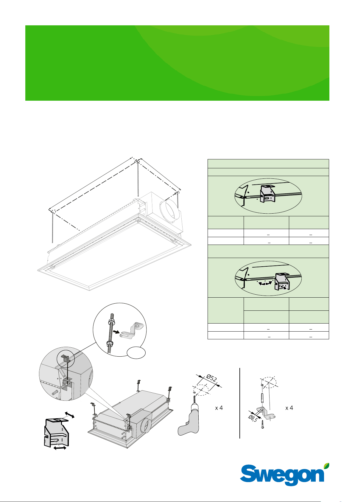
To mount the unit in the ceiling with standard mounting bracket/
Att montera produkten i taket med standard-upphängningsfäste
PARASOL Zenith 1200 / 1800
c - c dimensions / c - c mått
A
B
Bracket placement at delivery/ Fästets placering vid leverans
Enhetens längd/
Unit length
1200
1800
Alternative placement of the mounting bracket
Alternativ placering av upphängningsfästet
20180813
c - c (mm)
A
900 +20 508 +20
1528 +20 508 +20
c - c (mm)
B
20mm
M8
Enhetens längd/
Unit length
1200
1800
A2
A
A1
Out towards the corner
/Ut mot hörnet
c - c (mm)
A1
968 +20 832 +20
1528 +20 508 +20
Towards the center
/In mot centrum
c - c (mm)
A2
Page 2
PARASOL Zenith a
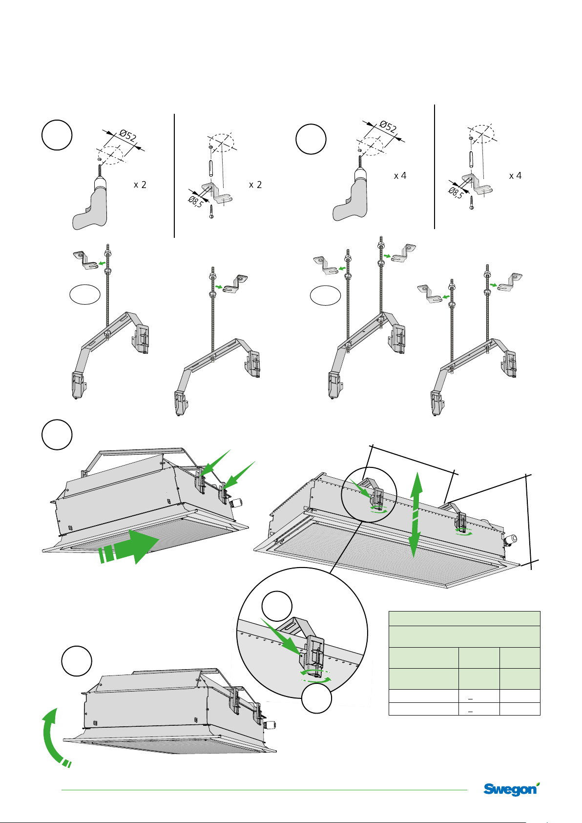
To mount the unit in the ceiling usig PARASOL Zenith accessory mounting bracket/
Att montera produkten i taket med PARASOL Zeniths tillbehörs-upphängningsfäste
PARASOL Zenith 1200 / 1800
1A
M8
1B
M8
2
3
5
5
4
c - c
c - c dimensions / c - c mått
Upphängningsfästets placering/
Mounting bracket placement
Luftanslutningssida/
Air connection side
Enhetens längd/
Unit length
1200
1800
Kortsida/
Short side
c - c (mm) c - c (mm)
< 1020 90 0 -1020
< 1530 900-1530
269 - 317
Långsida/
Long side
2
Swegon reserves the right to alter specications 20180813
Page 3
PARASOL Zenith a
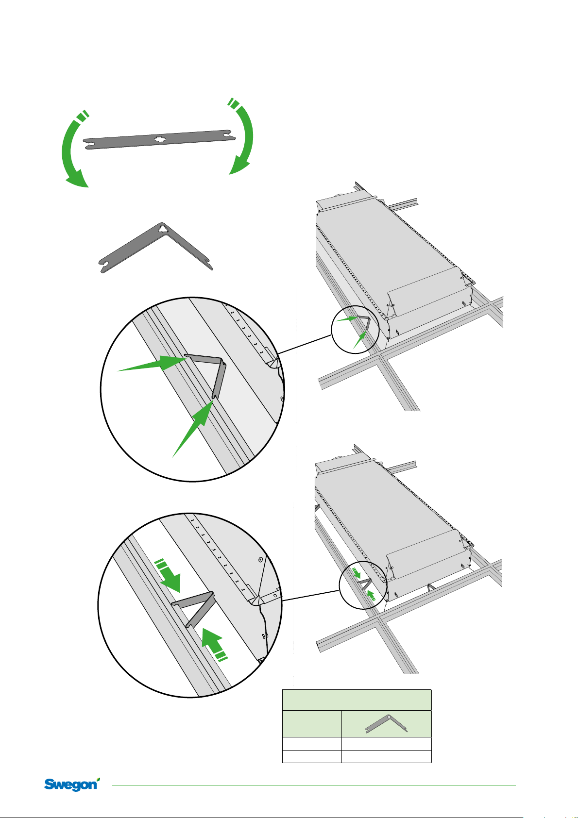
To center the product when mounting the product in hidden T-grid systems.
Att centrera produkten vid montering i dolt T-bärverk.
90°
Recommended number of plates per product /
Rekommenderat antal plåtar per produkt.
Enhetens längd/
Unit length
1200 6
1800 6-8
20180813 Swegon reserves the right to alter specications
3
Page 4

PARASOL Zenith a
Water connections / Vattenanslutning
PARASOL Zenith 1200 / 1800
PARASOL Zenith 1200 / 1800 PARASOL Zenith 1200 / 1800
B2
Värme retur/
Heating return
B1
Värme tillopp/
Heating supply
942256009
A2
Kyla retur/
Cooling return
A1
Kyla tillopp/
Cooling supply
Värme tillopp/
Heating supply
Connection dimensions / Anslutningsdimensioner:
Water connections without valves
Vattenanslutning utan ventiler
Inlet, chilled water/
A1
Tillopp kylvatten
Return, chilled water/
A2
Retur kylvatten
Inlet, heated water/
B1
Tillopp värmevatten
Return, heated water/
B2
Retur värmevatten
ø 12 × 1.0 mm (Cu)
ø 12 × 1.0 mm (Cu)
ø 12 × 1.0 mm (Cu)
ø 12 × 1.0 mm (Cu)
Water connections with factory fitted valves
Vattenanslutning med fabriksmonterade ventiler
A1
A2
B1
B2
B2
Värme retur/
Heating return
B1
Inlet, chilled water/
Tillopp kylvatten
Return, chilled water/
Retur kylvatten
Inlet, heated water/
Tillopp värmevatten
Return, heated water/
Retur värmevatten
Kyla retur/
Cooling return
Kyla tillopp/
942256009
ø 12 × 1.0 mm (Cu)
male threads, DN (1/2”) /
utvändig gänga, DN (1/2”)
ø 12 × 1.0 mm (Cu)
male threads, DN (1/2”) /
utvändig gänga, DN (1/2”)
Cooling supply
A2
A1
N.B!
Use support sleeves inside the pipes together with compression ring couplings.
OBS!
Använd stödhylsor i rören tillsammans med klämringskopplingar.
4
Swegon reserves the right to alter specications 20180813
Page 5

PARASOL Zenith a
Wiring diagram with factory mounted accessory URC1 Controller/
Inkopplingsschema för fabriksmonterat tillbehör URC1 Rumsregulator
For factory mounted accessory WISE IORE, see information for WISE gen.2, available for
download from www.swegon.com: WISE IORE Instructions for Use, WISE System Guide, WISE
Function Guide, WISE Project Planning Guide - VS, Cooling & Ventilation, Electric & Control
För fabriksmonterat tillbehör WISE IORE, se information för WISE gen.2, som finns för nedladdning från www.swegon.se: WISE IORE Bruksanvisning, WISE Systemguide, WISE Funktionsguide, WISE Projekteringsguide: - VS, Kyla & Ventilation, El & styr.
• CG-IV
• WCD2
green
yellow
white
brown
red
blue
grey
black
ANA 1
RES 2
RES 2
ANA 3
ANA 4
24V AC/DC
24V AC/DC
G0
G0
G0
G0
G0
| 1 2 | 3 4 | 5 6 | 7 8 | 9 10 11 12 |
24V
G0
0-10V DC
24V
G0
0-10V DC
24V
G0
| 22 | 23 | 24 | 25 |
|13 14 15 |16 17 18 |19 20 21 |
0-10V DC
• URC1
• POWER Aa
60 VA
• POWER Aa
20 VA
• SENSOR MODULE
• XXXX = Swegon accessory
Wiring diagram for accessories (without URC1 Controller)/
Inkopplingsschema för tillbehör (utan URC1 Rumsregulator)
brown (US=white)
blue (US=black)
brown (US=white)
blue (US=black)
• ACTUATORb
24V NC
• ACTUATORb
24V NC
External connections / Externa kopplingar
CONDENS
SENSOR
G0
G
24V
0-10V DC
black
white
G0
24V
0-10V DC
G0
• POWER Aa
60 VA
• POWER Aa
20 VA
942193004
∼24V AC
∼24
/ CCO
Internal connections / Interna kopplingar
WCD2
CONDENS
SENSOR
G0
G
∼24V AC
24V
/ CCO
0-10V DC
G0
24V
0-10V DC
G0
942193004
green
yellow
blue
red
brown
blue
brown
blue
• WCD2
• ACTUATORb
• ACTUATORb
24V NC
24V NC
20180813 Swegon reserves the right to alter specications
5
Page 6

PARASOL Zenith a
Menu:
To reach the menu, hold the left-hand and right-hand
buttons down for five seconds.
With the left-hand button ( ) you advance through the
menus. With the right-hand button ( ) you confirm your
selection.
Press the left-hand
button and select:
1. Alarm list
2. Commissioning air
Press the righthand button to
confirm your
selection
3. Commissioning water
6. Return to menu
1. Alarm list: See the complete alarm list to the right.
In the commissioning menus:
• Navigate between the menus by pressing the left-hand
button
• Confirm selections by pressing the right-hand button
• When a selection has been confirmed, the blue LED
will flash for about 60 seconds.
• In order to return to normal operation, select "no
adjustment"
3. Commissioning, Water:
3.1. Open the chilled water valve
3.2. Open heated water valve
3.3. No adjustment
6. Return to menu
2, 4 and 5 are not used
Meny sensormodul:
Genom att hålla ned vänstra och högra knappen i fem
sekunder når man menyn.
Med vänster knapp ( )stegar man sig igenom menyerna. Med höger knapp ( ) bekräftar man sitt val.
Tryck vänster knapp
och välj:
Bekräfta val med
högerknappen
1. Alarmlista
2. Injustering luft
3. Injustering vatten
6. Återgå till meny
1. Alarmlista:
Se komplett alarmlista till höger.
I injusteringsmenyerna:
• Stega mellan menyer med vänster knapp
• Bekräfta val med höger knapp
• När ett val bekräftats blinkar blå diod i ca 60 s.
• För att återgå till normaldrift, välj "ingen injustering"
3. Injustering vatten:
3.1. Öppna kylventil
3.2. Öppna värmeventil
3.3. Ingen injustering
6. Återgå till meny
2, 4 och 5 används ej
Function button
Temperature
sensor
Diode-indicating function
- Green = Ok
- Flashing Green = Condensation alarm
- Yellow = Alarm
- Green/Yellow=Comfort alarm, (not acute)
ON
1 2
Switch/Termination resistance. Switch 1 should
be ”on” for the last sensormodule in the loop.
Presence detector
Diodes for
temperature,
commissioning or
alarm indication
Function button
3 parallel RJ12 ports (Modbus) for
connecting a controller, another
sensor module or a computer, for
example, by means of a Cable
converter USB-RJ12
Dial for addressing the appropriate sensor module if several are
used in the same loop.
10 senormodules can be connected to the same master, and each
and one of them need an unique
address.
Närvarogivare
Funktionsknapp
Temperaturgivare
Funktionsknapp
Diod indikerande funktion
- Grön = Ok
- Blinkande Grön = kondenslarm
- Gul = Larm
- Grön/Gul = Komfortlarm (ej akut)
3 parallella RJ12 portar (modbus)
för anslutning av tex regulator, ytterligare sensormodul eller dator
med hjälp av Cable converter
USB -RJ12
ON
1 2
Adressering av sensormodul.
Till varje masterenhet kan 10 st
sensormoduler vara kopplade, var
och en måste ha sin unika adress
för att fungera.
Switch för termineringsmotstånd. Switch 1 sätts
till on på sista sensormodulen i slingan.
Dioder för
temperatur,
injustering eller
larmindikering
6
Swegon reserves the right to alter specications 20180813
Page 7

Alarm list for the sensor module
Alarmlista för sensormodulen
Alarm no. Type of alarm
Alarm nr. Typ av alarm
Alarm 1 Supply voltage low
Alarm 2 Supply voltage critically low
Alarm 3 Ext temp missing
Alarm 4 Ext temp error
Alarm 5 Condensation sensor error
Alarm 6 SM temp sensor error
Alarm 7 SM button error
Alarm 8 CO2 sensor missing
Alarm 9 VOC Error
Alarm 10 Low pressure
Alarm 17 SM comm error
Alarm 18 Slave comm error
Alarm 19 Pressure sensor comm error
Alarm 20 VOC sensor comm error
Alarm 21 No master request (slave)
Alarm 22 Slave incompatible version
Alarm 25 Heating comfort alarm
Alarm 26 Cooling comfort alarm
Alarm 27 Temp. Set point overlap alarm
Alarm 28 Air quality comfort alarm
Alarm 29 Condensation
Alarm 33 24 V Out 1 overload error
Alarm 34 24 V Out 2 overload error
Alarm 35 24 V Out 3 overload error
Alarm 41 Slave input common alarm
Alarm 42 Slave output common alarm
32 16 8 4 2 1
32 16 8 4 2 1
The alarm is displayed by
a number of diodes when
you have selected Alarm list
(1) in the menu.
Each diode represents a
number as shown in the
table above and the numbers should be added up to
form an alarm number.
Ex. The centremost blue
and the two last red diodes
are lit (xoxxoo)
The centremost blue one
corresponds to 16, the
penultimate red one to 2
and the last red one to 1.
The sum of these is 19,
which is the alarm number.
Return to normal operation
by pressing the right-hand
button.
PARASOL Zenith a
Larmet visas med ett antal
dioder när man valt Alarmlista (1) i menyn.
Varje diod representerar
ett tal enligt tabell ovan
och talen summeras till ett
larmnummer.
Ex. Mittersta blå och de två
sista röda lyser (xoxxoo)
Mittersta blå motsvarar 16,
näst sista röda 2 och sista
röda 1. Summan blir 19
vilket är larmets nummer.
Återgå till normaldrift
genom att trycka höger
knapp.
You can easily update the
software by connecting a
computer either to a socket
on the rear of the Sensor
module as illustrated, or
directly to the controller.
How this is done is described in the SWICCT user's
För att uppdatera mjukvaran kan man enkelt ansluta
en dator, antingen mot
baksidan av Sensormodulen, alternativt direkt mot
regulatorn.
Hur detta görs beskrivs i
manualen för SWICCT.
manual.
20180813 Swegon reserves the right to alter specications
7
Page 8

PARASOL Zenith a
Air connection / Luftanslutning
Enhet / Unit A =
1 2 3 4
PARASOL Zenith 1200 Ø 125 4
PARASOL Zenith 1200 Ø 160 5
A
1
2
4
3
PARASOL Zenith 1800 Ø 160 5
Change air connection side / Ändra luftanslutningssida
Change between side 2 and 4, or 1 and 3 / Ändra mellan sida 2 och 4, eller 1 och 3.
3
1
2
4
8
Swegon reserves the right to alter specications 20180813
Page 9

Commissioning / Injustering
Measurement of airflows / Mätning av luftflöden
PARASOL Zenith a
2
q
p = [Pa]
(
i
)
k
q = k · √p [l/s]
i
[pi Pa]
q [l/s]
k = k-faktor/-factor
ADC
0°
-40°
40°
Fan-shape
-40˚
X-shape
0˚
+40˚
20180813 Swegon reserves the right to alter specications
40
9
Page 10

PARASOL Zenith a
0
4
3
Nozzle configuration / Dysinställning
1
3 - 4 varv / 3 - 4 laps
2
3
T-25
1 x 8
1800
20 nozzle strips
20 dyslister
1200
16 nozzle strips
16 dyslister
0
1
2
3
4
5
Examples of the six different nozzle settings. / Exempel på de sex olika dysinställningarna.
1
2
3
4
5
0
Examples if you chose to have different nozzle setting on the nozzle strip/
Exempel där man väljer att ha olika dysinställning på dyslisten
2
10
Swegon reserves the right to alter specications 20180813
1
4
2
3
4
5
Page 11

k-factor / k-faktor
PARASOL Zenith a
Nozzle setting
/ Dysinställning
0
1
2
3
4
5
2
q
p = [Pa]
(
i
)
k
q = k · √p [l/s]
i
Nozzle strip / Dyslist k-factor / k-faktor PARASOL Zenith
per nozzle strip
/ per dyslist
Length/Längd: 1200
(16 strips/lister )
0 0 0
0,118 0,118x16 =1,89 0,118 x 20 =2,36
0,284 0,284x16= 4,54 0,284x20 =5,68
0,450 0,450 x16 =7,20 0,450x20=9,00
0,616 0,616x16=9,86 0,616x 20 =12,32
0,730 0,730x16 =11,6 8 0,730x20 =14,60
[pi Pa]
q [l/s]
k = k-faktor/-factor
Examples at different nozzle settings / Exempel vid olika dysinställningar.
Example/Exempel: PARASOL Zenith 1800.
Different settings of the twenty nozzle stripes. The long
sides have setting No. 4 on all 16 nozzle stripes and short
sides have setting No. 2 on all four nozzle stripes.
Olika inställning på de tjugo dyslisterna. Långsidorna har
inställning 4 på samtliga sexton dyslister och kortsidorna
ha inställning 2 på samtliga fyra dyslister
Exempel: PARASOL Zenith 1200.
Different settings of the sixteen nozzle stripes. One long
side and one short side have setting No. 3 and one long
side and one short side have setting No. 2.
Olika inställning på de sexton dyslisterna. En långsida och
en kortsida har inställning 3 och en långsida och en kortsida har inställning 2.
Length/Längd: 1800
(20 strips/lister)
0 1 2 3 4 50 1 2 3 4 50 1 2 3 4 5
0 1 2 3 4 50 1 2 3 4 50 1 2 3 4 5
0
0
1
1
2
2
3
3
4
4
5
5
0 1 2 3 4 50 1 2 3 4 50 1 2 3 4 5
0 1 2 3 4 50 1 2 3 4 50 1 2 3 4 5
PARASOL Zenith Length 1800
Nozzle setting/
Dysinställning
k-factor/nozzle strip/
k-faktor/dyslist
k-factor in total/
2 0,284 0,284 x 4 = 1,136
4 0,616 0,616 x 16 = 9,856
In total/Totalt: 10,992
0 1 2 3 4 5
0 1 2 3 4 5
0 1 2 3 4 5
0 1 2 3 4 5
k-faktor totalt
(20 strips/lister)
0 1 2 3 4 50 1 2 3 4 50 1 2 3 4 5
0 1 2 3 4 50 1 2 3 4 50 1 2 3 4 5
0
0
0
1
1
2
2
3
3
4
4
5
5
0
1
1
2
2
3
3
4
4
5
5
0 1 2 3 4 50 1 2 3 4 50 1 2 3 4 5
0 1 2 3 4 50 1 2 3 4 50 1 2 3 4 5
0
0
1
1
2
2
3
3
4
4
5
5
PARASOL Zenith Length 1200
Nozzle setting/
Dysinställning
k-factor/nozzle strip
k-faktor/dyslist
k-factor in total/
k-faktor totalt
(16 strips/lister)
2 0,284 0,284 x 8 = 4,54
3 0,450 0,450 x 8 = 3,6
In total/Totalt: 5,872
20180813 Swegon reserves the right to alter specications
11
Page 12

PARASOL Zenith a
To change nozzle configuration / Att ändra dysinställning
2 x
To change or remove the nozzle strip / Att byta eller ta bort dyslisten
1
x 2
1
2 x
2
3
12
Swegon reserves the right to alter specications 20180813
4
Page 13

PARASOL Zenith a
PARASOL Zenith with fold-out coil (option) for easy access and cleaning of the complete coil when stringent
demands are made on hygiene / PARASOL Zenith med fällbart batteri (tillbehör) för enkel åtkomst och
rengöring när det sälls höga krav på hygien.
1
2
3
4
5
20180813 Swegon reserves the right to alter specications
13
Page 14

PARASOL Zenith a
The accessory fold-out coil, requires flexible
hose connections on the water side.
Tillbehöret, fällbart batteri kräver flexibla
anslutningsslangar på vattensidan.
6
7
14
Swegon reserves the right to alter specications 20180813
8
9
Page 15

Maintenance / Skötsel
1
PARASOL Zenith a
2
3
4
5
6
20180813 Swegon reserves the right to alter specications
15
Page 16

PARASOL Zenith a
16
Swegon reserves the right to alter specications 20180813
Art.no. 942428034
 Loading...