

Page 1
GB.TBLZ47.130915
Registered design. The company reserves the right to make design changes without prior notice.
www.swegon.com 1
Installation Instructions for the TBLZ-1-47 Electronic Timer
GOLD/COMPACT/MIRUVENT
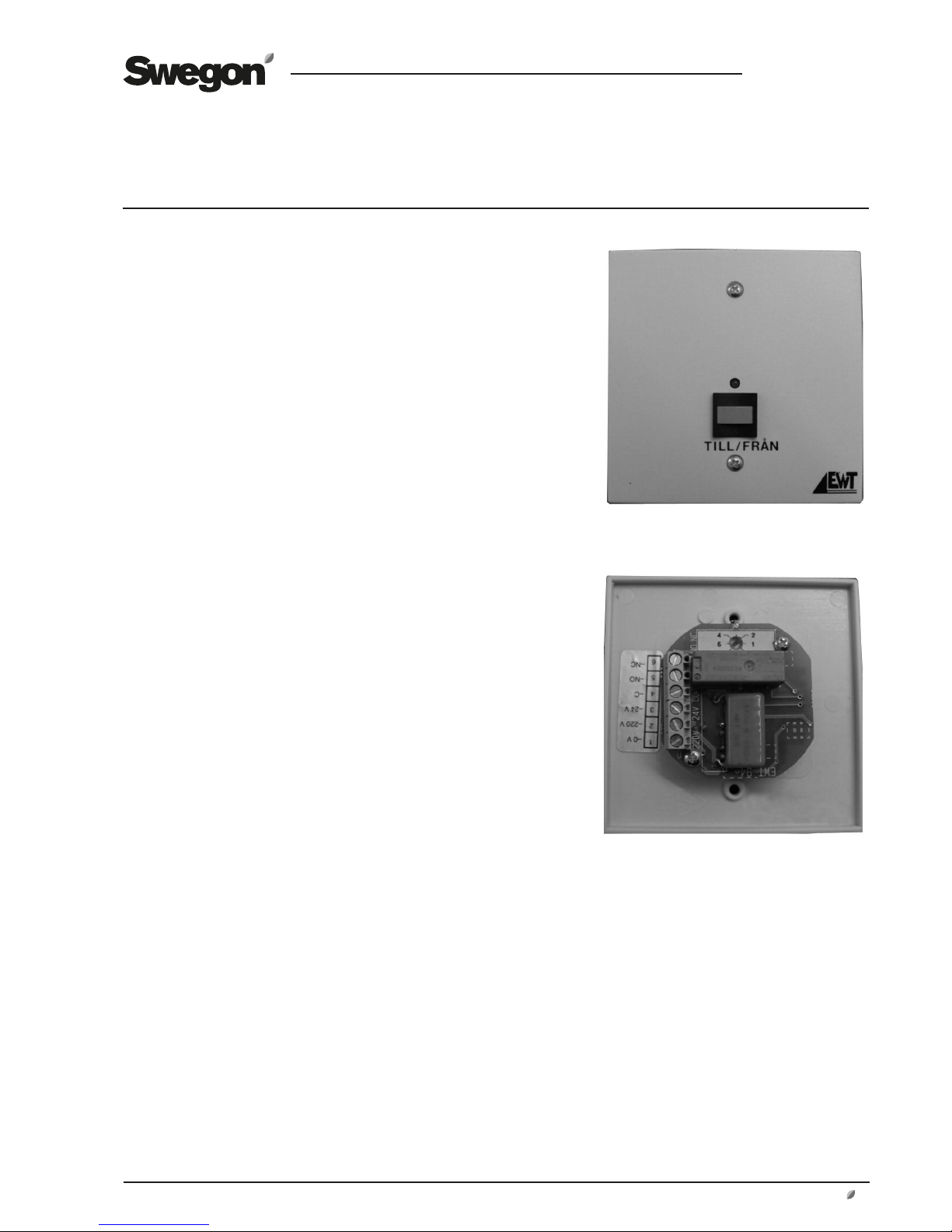
1. General
The TBLZ-1-47 electronic timer consists of a front plate
with spring-back pushbutton and indicating light-emitting
diode on the front. A circuit card, connection terminals
and a potentiometer for setting timer periods (0 – 6 hours)
are secured to the rear plate.
The kit also includes a mounting frame.
2. Range of Application
The timer is used for prolonged high-speed or low-speed
operation outside ordinary in-operation periods preset in
the internal timer (time switch) of the air handling unit/
power roof ventilator. The timer can also be used for controlling the air handling unit/power roof ventilator when
the internal timer is not in use.
3. Operation
The air handling unit/power roof ventilator is controlled to
the appropriate operating conditions via impulses from the
timer. The indicating light-emitting diode is lit when the
changeover relay switches on the signal to the air handling
unit’s/power roof ventilator’s input for external high speed
or external low speed. The relay is switched on and the
indicating LED is lit until the preset period has expired.
The timer function can be interrupted by pressing the
pushbutton once more. This is indicated when the LED is
no longer lit.
4. Installation
For flush mounting in electrical boxes with a mounting
dim. of 60 mm centre to centre.
The spacer frame supplied is used for surface mounting.
5. Technical Data
Supply voltage 24/220 VAC
Degree of protection IP 20
Colour White
Indication Green
Dimensions:
Push button 90 x 90 mm
mounting
frame (W x H x D) 100 x 100 x 30 mm
Rear
Front
Page 2
GB.TBLZ47.130915
Registered design. The company reserves the right to make design changes without prior notice.
2
www.swegon.com
1
G0
32
1)
G
31 14 15
2
3
4
1
2
3
4
NO
NC
C
220 V
24 V
0
NO
NC
C
220
V
24 V
0
1
G0
32
1)
G
31 16 17
2
3
4
1
2
3
4
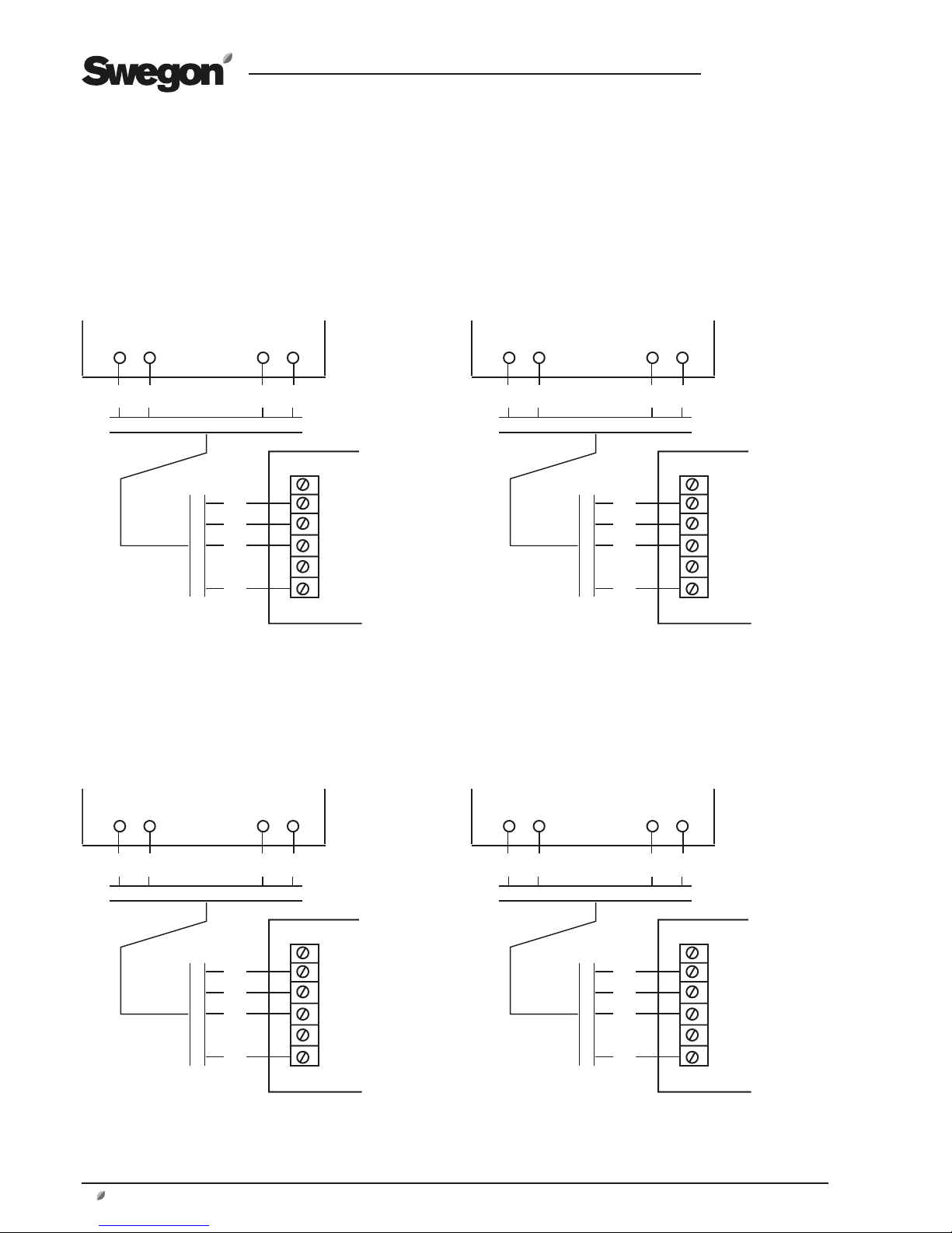
6. Electrical Connections.
The electrical connections should be wired by a qualified electrician
in accordance with local electrical safety regulations.
Terminals on the control unit
Terminals on the control unit
Low speed High speed
GOLD RX/PX/CX/SD, version E
Terminals on the timer Terminals on the timer
Terminals on the control unit
Terminals on the control unit
Low speed High speed
GOLD RX/PX/CX/SD, version D
1
G0
61
1)
G
60 46 47
2
3
4
1
2
3
4
NO
NC
C
220 V
24 V
0
NO
NC
C
220
V
24 V
0
1
G0
61
1)
G
60 48 49
2
3
4
1
2
3
4
Terminals on the timer Terminals on the timer
1)
Applies to GOLD size 100/120 only:
If the total load on wiring terminals 31-32 is higher than 16 VA,you should wire the leads to terminals 201 (G) and 202 (G0). Wiring terminals 201-202
can be loaded with a total of max. 48 VA.
1)
Applies to GOLD size 100/120 only:
If the total load on wiring terminals 58-59 and 60-61 is higher than 16 VA,you should wire the leads to terminals 201 (G) and 202 (G0). Wiring terminals 201-202 can be loaded with a total of max. 48 VA.
Page 3

GB.TBLZ47.130915
Registered design. The company reserves the right to make design changes without prior notice.
www.swegon.com 3
GOLD LP/COMPACT
1)
The external low-speed function must be selected in the micro termi-
nal. See the Installation and Maintenance Instructions.
2)
The external high-speed function must be selected in the micro termi-
nal. See the Installation and Maintenance Instructions.
1
G010G
95
1)
6
2
3
4
1
2
3
4
NO
NC
C
220 V
24 V
0
NO
NC
C
220
V
24 V
0
1
G010G
97
2)
8
2
3
4
1
2
3
4
Low speed High speed
Wiring terminals on the control unit
Wiring terminals on the control unit
Low speed High speed
MIRU Control
16 17
1
2
2
3
1
1
2
NO
NC
C
220 V
24 V
0
18 19
1
2
2
3
1
1
2
NO
NC
C
220
V
24 V
0
Wiring terminals on the timer Wiring terminals on the timer
External power
supply
External power
supply
Page 4

GB.TBLZ47.130915
Registered design. The company reserves the right to make design changes without prior notice.
4
www.swegon.com
 Loading...