

Page 1

LUNA d
Instructions for Use
Contents
Introduction ....................................................... 2
1.1 Introduction .......................................................... 2
1.2 Selection of room temperature ............................. 2
1.3 LED status lamp .................................................... 2
System overview and installation ..................... 2
2.1 System overview ................................................... 2
2.2 Terminal functions ................................................ 2
2.3 Invert heating outputs ........................................... 3
2.4 Resetting .............................................................. 3
2.5 Hand-held terminal LUNAb T-CU .......................... 3
Control functions ................................................ 4
3.1 Operating modes .................................................. 4
3.2 Setting room temperatures ................................... 4
3.3 Deadband ............................................................. 4
3.4 Control process ..................................................... 4
3.5 P-function ............................................................. 4
3.6 I-function .............................................................. 4
Inputs and sensors .............................................. 5
4.1.1 Sens or t ype ........................................................ 5
4.1.2 Average value measurement ............................... 5
4.2 Occupancy sensor ................................................. 6
4.2.1 Switch-on delay ................................................. 6
4.2.2 Switch-off delay ................................................. 6
4.2.3 Inverting the occupancy signal ........................... 6
4.3 Overriding the operating mode ............................. 6
4.3.1 Forced output when external contact function
is activated ...................................................................6
4.4 Condensation sensor ............................................ 6
4.4.1 Select effect of output A1 ................................. 6
13 /11 / 2018
Article xxxxxxxx
Outputs and actuators ....................................... 7
5.1 Actuator ............................................................... 7
5.2 Output signals ...................................................... 7
5.3 Heating, cooling or direct temperature .....................
control of output .................................................. 7
5.4 Limitation of control range .................................... 8
5.5 Temperature limits for
“direct temperature control” (see 5.3)...................... ..8
5.6 Setting the voltage limits for outputs A1 and A2 ... 8
5.7 Inverting the output .............................................. 8
5.8 Periodic valve operation ........................................ 8
Menu functions with hand-held unit ................ 9
6. Hand-held terminal ................................................. 9
6.1.1 Restoring the factory settings ............................. 9
6.1.2 Quick guide: ....................................................... 9
6.2 Hand-held terminal’s different modes ................. 10
6.2.1 Local mode (the settings are made in the tool) . 10
6.2.2 Read mode ...................................................... 10
6.3 LUNAd T-CU buttons .......................................... 10
6.4 Display symbols ...................................................11
6.5 Navigation under the main menu .........................11
6.6 Navigation under the settings menu .....................11
6.7 Change values .....................................................11
6.8 Display overview ................................................ 12
6.9 Week program .................................................... 14
6.10 Log function ..................................................... 14
6.11 Control settings ................................................. 14
6.12 Outputs, settings ............................................... 15
6.13 Outputs, Settings ...............................................17
6.14 Occupancy ........................................................ 18
6.15 Calibration of temperature sensors .................... 19
6.16 Button functions ............................................... 20
6.17 Test Menu ......................................................... 21
6.18 Type designations .............................................. 23
The document was originally written in Swedish.
Page 2

LUNA d
Introduction
1.1 Introduction
LUNAd is a room controller that gives a stable and
comfortable room temperature through efficient and
accurate control and regulates the different heating and
cooling actuators. The room controller has four outputs
that can individually be adjusted to suit most requirements.
In the supplied version the room controller is set to control
heating and cooling actuators with 24 V AC and 0–10 V DC.
The room controller has a built-in temperature sensor for
detection and setting of the room temperature.
Different types of sensors can be connected to the room
controller.
If you need to change the settings on a room controller
a special hand-held terminal with display (LUNAd T-CU)
is required. The hand-held terminal is then connected
temporarily to the room controller’s 4-way connector. The
connector is located behind the room controller’s cover.
If you wish to install an external sensor in the room or
e.g. in the air duct, the sensor is connected to the screw
terminals in the room controller. The external sensor is then
activated automatically.
Even different types of sensors can be connected to the
controller, for example, occupancy sensor, condensation
sensor, extra temperature sensor or an external contact.
The external sensor’s functions can be set on the menus
on the hand-held terminal with display.
The room controller has three different operating modes
(day, night and save) that can activate different room
temperatures.
1.2 Selection of room temperature
The temperature is set by adjusting by turning the adjuster
knob. The adjuster knob always controls the required
temperature in DAY operating mode, irrespective of whether
any other operating mode is active. It is not possible to
see which operating mode is currently active, but with the
help of the large LED you can see whether the controller is
in heating mode, cooling mode or in standby (dead zone).
The scale of the adjuster knob is not graduated (i.e. no
numbers), so that it is possible to change the adjuster
knob’s temperature range. On delivery the adjust knob’s
range is 19–25 °C with the set point 22 °C in the middle
of the set point scale. Turn the adjuster knob up (clockwise) you increase the temperature and vice versa.
System overview and
installation
2.1 System overview
The room controller can be configured in a variety of
ways. The controller has been especially developed to
facilitate customisation without the need making and
changes to the hardware. The room controller can be
directly connected to numerous different control systems
without the need to make any settings. These are
described in this chapter.
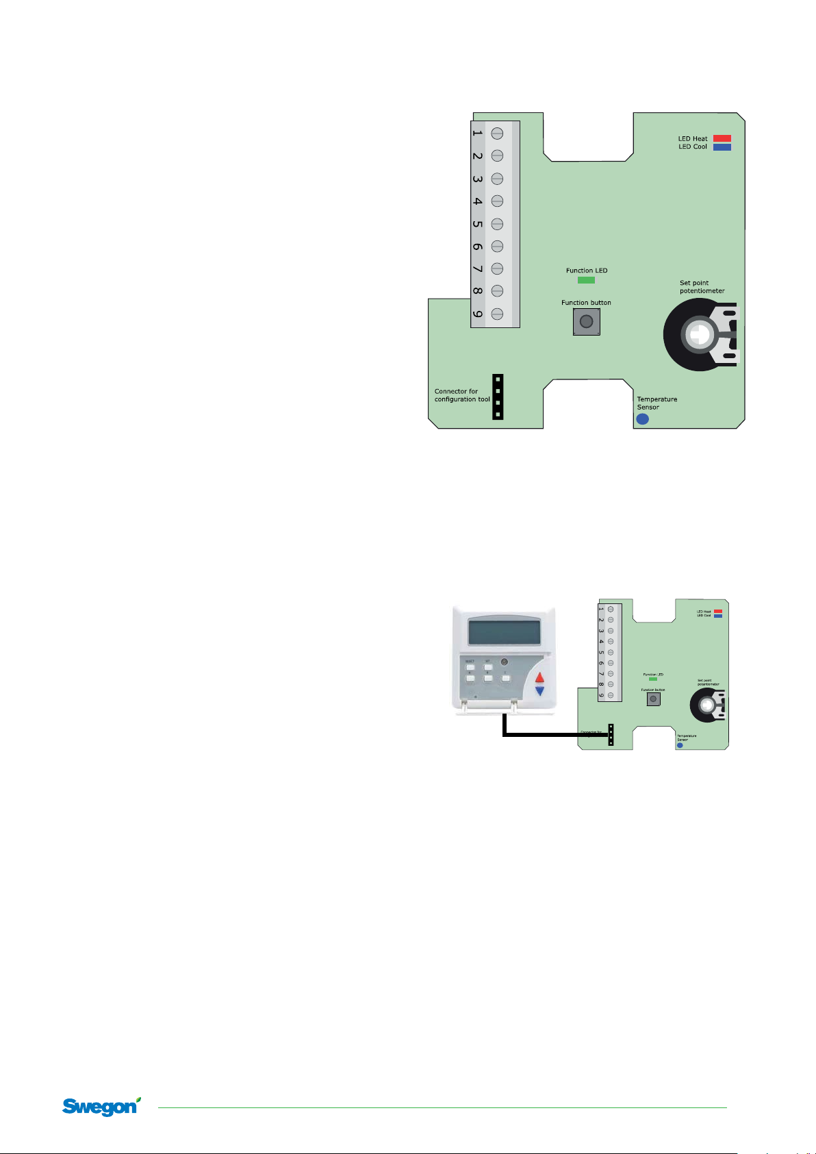
2.2 Terminal functions
The screw terminals on the controller have different markings
and placements. The following figure describes the screw
terminals in a factory set room controller:
1. Output D1 - 24 V Cooling actuator (0 V)
2. Common phase 24V AC for actuator
3. Output D2 - 24 V heating actuator (0 V)
4. Analogue output A1, 0–10 V DC, cooling
1.3 LED status lamp
The room controller is equipped with a LED status lamp
that indicates the current output signal. The LED lamp can
also display other operating modes. In normal mode the
LED lamp displays the following:
1. Blue = cooling requirement
2. Red = heating requirement
3. Flashing blue = condensation (only when the condensation function is active in the room controller and the
operating mode is cooling requirement.
2
Swegon reserves the right to alter specications. 13/11/2018
5. G, phase 24V AC from transformer
6. G0, 0V from transformer
7. Analogue output A2, 0–10 V DC, heating
8. Input for external temp. sensor
9. Input for condensation sensor
Page 3
2.3 Invert heating outputs
There is a button under the cover on the controller. The
button can be used to invert all the heating outputs.
1. Set the temperature potentiometer to its lowest position.
2.
3.
Press and hold the button for about 12 seconds.
The room controller now inverts all the heating outputs.
Repeat the procedure to remove all the inverted heating
outputs.
2.4 Resetting
There is a button under the cover on the controller.
The button can be used to reset the memory according to
the customer’s configuration.
1. Switch off the power to the controller.
2.
3.
Press and hold the button while you switch on the
controller.
Release the button, the controller now performs a
customer reset.
LUNA d
2.5 Hand-held terminal LUNAb T-CU
On the room controller’s PCB, behind the cover, is a 4-way
outlet where the hand-held terminal can be connected.
Using this it is possible to configure different settings in
the room controller.
All the settings are described in the manual, chapter 6
13/11/2018 Swegon reserves the right to alter specications.
3
Page 4

LUNA d
Control functions
The room controller regulates the temperature in the
room with the help of a heating elements and/or chilled
beams. The room controller compares the set temperature
with the current measured room temperature and controls
via its outputs the heating or cooling to the room.
3.1 Operating modes
The room controller has three operating modes each with
its setting values for room temperature and “deadband”.
Other functions can also be connected to the different
operating modes. The operating modes can be controlled
by the following functions in priority order:
1. External contact
2. Occupancy
3.2 Setting room temperatures
The room temperature is adjusted individually for the
three operating modes with the help of the hand-held
terminal LUNAd T-CU.
Using the adjuster knob on the room controller you
can only adjust the desired temperature for DAY mode.
The desired temperature is also called the “set point”.
The measured room temperature is also called the “actual
value”.
3.4 Control process
A slightly simplified control works as follows, step by step:
1. The room controller selects the right temperature and
deadband taking into consideration the enabled
operating mode.
2. The controller calculates the regulated setpoints for
cooling and heating that are equal to the setpoint ±
half the deadband.
3. If the temperature has been higher than the regulated
set point for cooling, the controller is set to cooling
mode and uses the regulated set point for cooling when
regulating.
4. The deviation between the desired temperature and
the measured temperature can be calculated.
5. The capacity value for heating or cooling is calculated.
6. The room controller’s i-function detects if the temperature deviation has not been corrected for a long
period, and if necessary adds an extra “boost” to the
capacity values.
7. The capacity values are converted to output signals and
are sent to the different outputs.
3.5 P-function
The room controller’s method of control is known as “PI”,
which is an abbreviation of proportional and integral. The
proportional function (p-function) means that the controller
calculates a capacity requirement that is proportional to
the temperature deviation.
3.3 Deadband
The room controller has a neutral zone between heating
and cooling control that is called the deadband. This
function is used to prevent both the heating and cooling
outputs from being connected at the same time, and
to save energy. However, the room controller permits
the temperature to deviate a half degree up or down
compared to the set point temperature, before a control
signal is sent to the heating elements or chilled beams.
This applies in DAY operating mode.
In NIGHT mode and SAVE mode the deadband is wider, to
give an economy function when you are not in the room.
When the hand-held terminal is connected it is possible to
adjust the three different deadbands under menu 3.
For DAY operating mode: function “DB.D”
For NIGHT operating mode: function “DB.N”
For SAVE operating mode: function “DB.S”
When high climate comfort is required, the deadband
should be relatively small. However, the deadband should
be wider to save energy.
If the room controller is set to only control heating or
only cooling, then the deadband has not function, and
the room temperature is then controlled directly to the
temperature set for each operating mode.
The P-band can be configured under menu 3.
P-band for heating: function “P.H”
P-band for cooling: function “P.C”
3.6 I-function
The integral function (i-function) means that the room
controller continuously monitors the capacity requirement
that the p-function gives. This helps to smooth out the
deviation more accurately than what the p-function can
sometime achieve, for example, due the heating element
or chilled beam needing a higher control signal to be able
to reach the right temperature in the room.
The I-function can be configured under menu 3.
I-time for heating: function “I.H”
I-time for cooling: function “I.C”
4
Swegon reserves the right to alter specications. 13/11/2018
Page 5

Inputs and sensors
The room controller has a fixed input for the condensation
sensor and a programmable input for the external sensor.
Depending on the selected function, a sensor can be of
the thermistor type for temperature monitoring (resistive),
condensation detection (resistive) or a contact (0 V or no
contact).
The condensation sensor is connected between terminal
block 9 (input) and terminal block 6 (G0).
An external sensor (resistive or contact) is connected
between terminal block 8 (input) and terminal block 6 (G0).
The configuration tool can be used to select the type of
sensor you wish to connect.
There are four different sensor functions:
Type Input
1. Condensation sensor 9. Condensation
2. External temperature sensor 8. Termistor,NTC,10K
3. Presence sensor 8. Contact:
4. Operating mode contact 8. Contact:
LUNA d
4.1.1 Senso r t yp e
Two types of sensor can be used for temperature control:
a) in-built sensor
b) external resistive sensor (NTC, 10 kOhm at 25°C)
The built-in sensor in the room controller is always used
automatically by the room controller if no other sensor
is connected to the terminal. When an external, resistive
sensor is connected, the room controller selects this
sensor automatically instead of the built-in sensor.
4.1.2 Average value measurement
In order to connect the average value measurement with
both an external sensor and the built-in sensor in the
room controller, set the following on menu 5 (input):
Function “R1+R2” can be set to 1, 2 or 3
1 = internal sensor only
2 = external sensor only
3 = average value between internal and external sensors
If value 3 is used and if no other sensor is connected to
the terminal, the room controller only reads the internal
sensor.
13/11/2018 Swegon reserves the right to alter specications.
5
Page 6

LUNA d
4.2 Occupancy sensor
It’s possible to connect an occupancy sensor that enables
the DAY operating mode when occupancy is detected
and which enables NIGHT operating mode when the
occupancy indication ceases. A switching on and off delay
for the DAY operating mode can be set.
The presence sensor can have a contact output (normally
open or normally closed) which is connected between
terminal block 8 (input) and terminal block 6 (G0). G0 is the
signal that the sensor switches on and off to the input.
The presence sensor is activated with the help of the
configuration tool, under menu 6 and the function
“ACTIVE” (enable).
Då närvarogivare är aktiverad, inkopplas driftläget NATT i
stället för DAG när närvaro indikeras. Då närvaro indikeras
inkopplas driftläge DAG.
4.2.1 Switch-on delay
When occupancy has been indicated at some time
both during the first and second half of the delay time,
the DAY operating mode is enabled after the time has
expired. This operating mode remains enabled as long as
there is an occupancy indication.
The switch-on delay for occupancy is selected under
menu 6:
Function “TIME1”: select the delay time for switching on
4.3 Overriding the operating mode
With the 0 V-signal from an external contact you can force
any of the room controller’s four outputs. the contact is
connected between terminal 8 (input signal) and 6 (G0).
Enabling the external contact function is selected under
menu 5 with the help of the hand-held terminal LUNAd
T-CU.
Function “EXT.”:
0 = external contact function disabled
1 = external contact function enabled
4.3.1 Forced output when external contact
function is activated
When the external contact function is enabled it is possible to select which of the outputs is to be forced to open
(0 V to terminal 8).
Activation of forcing output is selected under menu 4,
OUTP”:
First select the output under the function “OPno”:
D1 = 24 V output terminal 1
D2 = 24 V output terminal 3
A1 = 0–10 V output terminal 4
A2 = 0–10 V output terminal 7
4.2.2 Switch-off delay
The switch-off delay delays the disabling of DAY operating
mode when occupancy indication from the sensor ceases. The
time is adjustable between 0 and 990 minutes. The resolution is
10 minutes over 100 minutes.
The switch-off delay for occupancy is selected under menu 6:
Function “TIME0”: select the delay time for switching off
4.2.3 Inverting the occupancy signal
The input function can be inverted to select either an
occupancy sensor that has a normally open or normally
closed contact for occupancy indication.
Inverting the occupancy signal is selected under menu 6:
Function “NO”: 0 = (NC, normally closed) is
opened when occupancy is
detected
1 = (NO, normally open) closes
when occupancy is detected.
Select the function “FORC.”:
0 = forcing of output disabled
1 = forcing of output enabled (when the external
contact is enabled with 0 V to the input on
terminal 8).
4.4 Condensation sensor
It is possible to connect a condensation sensor to input I1
(between terminal 8 and terminal 6) to disable all cooling
outputs and generate an alarm for high condensation of
output A1.
The condensation input is designed for resistive condensation sensors, with resistance values between 50 K and
900 kΩ (for condensation).
The condensation function is set under menu 5 with the
help of the hand-held terminal LUNAd T-CU.
Function “COND” 0 = condensation disabled
1 = condensation enabled
4.4.1 Select effect of output A1
If this function is enabled, the controller activates the 10 V
DC output on Y3 (terminal 4) when condensation occurs.
Function “CALRM” 0 = alarm signal disabled
1 = alarm signal enabled
6
Swegon reserves the right to alter specications. 13/11/2018
Page 7

LUNA d
Outputs and actuators
The room controller has two 24 V outputs (d1 and d2) and two
analogue 0–10 V outputs (A1 and A2).
Actuators are connected to the following terminal blocks:
• d1: terminal block 1 and 2.
• d2: terminal block 3 and 2.
• A1: terminal block 4 (+), terminal block 6 (G0) and to G
(phase 24 V AC).
• A2: terminal block 7 (+), terminal block 6 (G0) and to
G (phase 24 V AC).
An output can be affected by the following functions (the
uppermost has the highest priority):
1. Output affected by the condensation sensor
2. Output “active” for test activation
3. Output “active” if the function “FORC.”=1 under
menu 4 when input I2 is set to the contact
function “EXT.” = 1.
Under menu 4 (“OUTP”) you can select the type of
regulation outfeed and other settings for each output.
Select the output to be set:
Function “OPno” select d1, d2, A1 or A2.
5.1 Actuator
In this context an actuator is an electro-mechanical unit
that is governed by an electrical signal from the controller
and manoeuvres, e.g. a valve or damper to close.
5.2 Output signals
Different actuators require different output signals from
the room controller. The outputs are therefore adjustable
for different types of actuator.
Pulse regulating (24V or 0-10V)
Normally used to control thermal actuators or for electrical
heating control.
ON/OFF control (24V or 0-10V)
Normally used for the control of 2-position damper
motors or electrical heaters via contactors.
3-p regulating (24V)
Normally used to control increase/decrease actuators.
0-10 V regulation (0-10 V)
Normally used to control 0-10 V actuators.
5.3 Heating, cooling or direct temperature
control of output
You can choose whether an output should control a
heating actuator, a cooling actuator or an actuator for
both heating and cooling.
The setting of functions that follow “OPno” only apply to
the selected output.
When “3P” has been selected for output D1, the settings
refer to both outputs d1 and d2, as this outfeed uses both
the digital outputs.
The room controller outputs a heating and cooling
capacity values between 0–100 % to the outfeed logic.
A capacity value is calculated for each individual output
based on this value (and depending on the following
settings for each output).
A cooling actuator is only activated when the controller
outputs a capacity value for cooling. A heating actuator
is only activated when the controller outputs a capacity
value for heating.
An actuator that is directly controlled by the room
temperature is not affected by the controller’s fed capacity,
but only by the selected limit value for the room temperature.
Go to the function “HC” under menu 4, and set the
following selections for the required output:
COOL: for the regulation of cooling
HEAT: for the regulation of heating
HC: for the regulation of both cooling and heating
dIFF: for direct temperature control
In “HC” mode, 0–5 V is fed with a cooling requirement
100–0 % and 5–10 V for a heating requirement 0–100 %
on outputs A1 and A2.
It is possible to set the controller so that the 0–10 V outfeed to output A1 is available both for heating and cooling
requirement to control of an actuator on a 6-way valve.
13/11/2018 Swegon reserves the right to alter specications.
7
Page 8

LUNA d
5.4 Limitation of control range
(does not apply if “direct temperature regulation of
output” is selected)
The room controller calculates a capacity value between
0–100 % which is sent to the outfeed logic. You can
choose, for each output, whether it should regulate
within the whole or part of this range.
Example:
If, for example, you have selected an output that regulates
within the range 20–50 %, the capacity to the actual
output will be regulated as follows:
Capacity from the controller Capacity outfeed to the output
0–20 % 0%
20–50 %0 –100%
50 –100 %100 %
This function can be used, for example, to control output
in sequence.
5.6 Setting the voltage limits for outputs
A1 and A2
The voltage on outputs A1 and A2 are normally between
0–10 V, but the values can be limited upwards or downwards.
The voltage from output A1 and A2 does not drop below
the selected minimum value in the function “LIML V” and
does not exceed the selected max value in the function
“LIMH V”.
Exceptions For the condensation indication the voltage is
set to 0 V, irrespective of the value for the function “LIML
V”.
5.7 Inverting the output
Inverting means that the outputs D1 and D2 close instead
of open and vice versa.
For an increase/decrease outfeed the outputs with work
in reverse so that the actuator changes rotation direction.
Go to menu 4, and set the following selections for the
required output:
LIML%: the low capacity limit in %
LIMH%: the high capacity limit in %
5.5 Temperature limits for “direct tem-
perature control” (see 5.3)
When “dIFF” is selected in the function “HC”, the output
is not regulated to the capacity value from the controller,
but directly by the selected room temperature limits.
Set a temperature range with the functions “LIM.-1” and
“LIM.-0”. When the temperature is within the range and
“PULS”-, “3P”-, “OnOff” or “0-10” regulation is selected,
the capacity is outputted to output by the temperature
value in relation to these limit values.
When the temperature reaches “LIM.-1” or is outside of
this value, 100 % of the capacity is fed to the output.
Output A1 and A2 give 10–0 V instead of 0–10 V, for
example 7 V becomes 3 V instead.
Inverting of the output signal is set under menu 4:
Function “INV.” select 0 (not inverted)
select 1 (inverted)
5.8 Periodic valve operation
Some valves need to be “test run”, i.e. periodically
opened and closed to not jam or seize.
Test running occurs at optional daily intervals:
D1 and A1 open at 01:00–01:03.
D2 and A2 open at 01:30–01:33.
The setting for test running is set under menu 4:
The function “MOT” select the number of days between
test running. The value 0 disables test running.
When the temperature reaches “LIM.-0” or is outside of
this value, 0 % of the capacity is fed to the output.
8
Swegon reserves the right to alter specications. 13/11/2018
Page 9

Menu functions with
hand-held unit
6. Hand-held terminal
The hand-held terminal/tool is used to read and change
the settings in the controller. The tool communicates with
the controller with the help of a cable that is connected
to the 4-way outlet on the controller’s circuit board. All
settings in the controller are shown under different menus
in the tool.
The settings can be changed and stored locally in the
unit’s own memory and then downloaded to the controller.
Alternatively the values in the controller can be transferred
to the tool and in this stage any changes are stored in the
settings both in the tool and the controller.
6.1.1 Restoring the factory settings
Prior to use it is usual to make a factory reset of the tool so
that old configured values are not accidentally fed into the
controller. A reset is performed with the power switched
off by holding down the buttons A, B and C and at the
same time powering up the unit (for example, by connecting
it to the controller. When you release the buttons A, B and
C the tool is reset to the factory settings.
LUNA d
6.1.2 Quick guide:
a) Factory reset
Hold down the three buttons (A, B and C) and power up.
The tool’s memory is reset to the factory
settings when the buttons are released.
b) Change the values in the tool’s local memory
Press the A button under the tool’s cover (activates
local mode). The settings are only stored in the local
memory and are not transferred to the controller.
c) Transfer settings from the controller to the tool
Press the B button under the tool’s cover.
When a “one” is shown it is possible to read the controller’s
values on the tool’s display. Note that the values are not
stored in the tool’s permanent memory.
The tool only reads the values from the controller and
shows them on the display. The downloaded values in the
tool cannot be transferred to another controller once the
tool’s power has been switched off as the unit loses all
data that has been downloaded.
d) Changed settings from the tool
Download data from the controller by pressing the B
button under the tool’s cover. If changes are made in
the settings, the settings are downloaded to the controller and are saved in the tool’s memory at the same time
(data is stored in tool).
e) Download the settings to the controller
Press and hold the C-button under the tool’s cover for
3 seconds until a zero is shown. After a few seconds a
“one” is shown and all settings have been downloaded and stored in the controller’s memory.
13/11/2018 Swegon reserves the right to alter specications.
9
Page 10

LUNA d
6.2 Hand-held terminal’s different modes
6.2.1 Local mode
(the settings are made in the tool)
This is the start-up mode after a power failure.
A sun or moon symbol is not displayed.
Any changes in the settings are only made in the
permanent memory. To change the mode to read mode,
press the A-button, so that “LOCAL 1” is shown.
6.2.2 Read mode
This mode is activated when you press the B-button or
the C-button.
B-button (activates read mode).
When you press the B-button, “READ 0” is shown.
After a few seconds “READ 1” is shown when the
settings in the controller are copied to the tool. The
copied settings are NOT saved in the permanent memory
in the tool. These settings cannot be copied to another
controller. When the power to the tool is switched off,
the unit loses the settings that have been copied.
6.3 LUNAd T-CU buttons
The figure shows the placement of the different buttons
on the hand-held terminal for LUNAd T-CU. All functions
and settings in H202 can be accessed using the buttons.
The buttons have the following functions:
A P(0) reset must be performed to copy the settings from
the volatile memory to the permanent memory. This is
done from the RESET function under the TEST menu.
Settings made in “Read mode” are transferred to the
controller and are also copied to the permanent memory
in the tool.
C-button (activates read mode).
When you press the C-button for three seconds,
“PRO! 0” is shown.
After a few seconds “PRO! 1” is shown, where the settings
from the permanent memory in the tool are downloaded
to the permanent memory in the controller. A sun or
moon symbol is shown (this denotes that the tool is
connected to the controller and that read mode is active).
SELECT = Menu selection under the main menu (goes
through the principle menu functions)
SET = change display values
Arrow up = increase the value, alternatively go to the
next function in the menu
Arrow down = decrease the value, alternatively go to the
previous function in the menu
A = Activates local mode in LUNAd T-CU
B = Activates read mode in LUNAd T-CU
Transfer all settings from LUNAd RE to
LUNAd T- CU
C = Activates read mode. Download all settings
from LUNAd T-CU to LUNAd RE.
10
Swegon reserves the right to alter specications. 13/11/2018
Page 11

operating
mode
Output
Text eld Numerical eld
Tools Menu symbol
6.4 Display symbols
The display symbols have the following functions:
1. Sun, Day operating mode
2. Moon, Night operating mode
3. Sun + Moon = Save operating mode
4. HEAT = output signal for heating is activated
5. COOL = output signal for cooling is activated
A flashing cooling symbol indicates condensation if
this function is activated and the output signal for
cooling is activated.
6. Tool = the setting menu
7. MENU = main menu
LUNA d
6.5 Navigation under the main menu
Press the SELECT button to go to the main menu.
Each menu option has four different functions and are
described in this manual. Some menus are based on
submenus below a master menu. Here you always move
sideways by pressing one of the arrow keys.
6.6 Navigation under the settings menu
Press the SELECT button until the tool symbol is displayed
to navigate
between the different settings menus. The current
active settings menu is shown with the name and menu
number. Pres the SET button and the menu number will
start to flash. You can now select the menu you wish to
navigate to by pressing the arrow up or down. Once you
have selected the menu you wish to navigate to, press the
SET button again to confirm the choice (the value stops
flashing). You can now navigate in this menu and its
functions by pressing the arrow up or down.
If you press the SELECT button when in a menu, the tool
returns to its standard view (shows the room temperature).
If you wish to return to the settings menu just press
the SELECT button several times until the tool symbol is
shown. When you have navigated to the active settings
menu you can navigate through its functions with arrow
up or down.
6.7 Change values
To change the value on the display, press the SET button.
The selected setting on the display starts to flash. This
indicates that the value can be changed. Change the
value by pressing arrow up or down.
Change grouped values
Sometimes a group of values is shown and the SET button
goes through these values one at a time. If a group of
values shows “0 0 0” and the middle value needs to be
changed, press the SET button twice to access the middle
number (the middle number starts to flash) use arrow
up to increase or arrow down to decrease the value.
Complete the change by pressing the SET button again to
leave “change value mode”. The value stops flashing.
13/11/2018 Swegon reserves the right to alter specications.
11
Page 12

LUNA d
6.8 Display overview
Basic view
HEAT HEAT
ROOM MON.
HEAT
TIMER
SUB MENU
RED
BLUE
°C
21.0 12:25 01:01 17:01 100
MENU
HEAT HEAT HEAT
DATE Y:W %OUT
MENU MENU MENU
0:00
MAIN MENU
SETTINGS
MENU
SELECT
RED
SET
BLUE
HEAT
DAY
HEAT
NITE
HEAT
SAVE
Week
program
HEAT
W.PR.
Log
HEAT
LOG
Controller
functions
HEAT
REGUL
Output
HEAT
OUTP
Inputs
HEAT
INPUT
Type menu
HEAT
OCC.
Modbus
HEAT
CAL.
Button functions
HEAT
BUT.F
Times and
measurements
HEAT
TEST
Set point
HEAT
TYPE
22.0
22.0
22.0
MENU
MENU
MENU
MENU
MENU
MENU
MENU
MENU
MENU
MENU
7
MENU
8
MENU
9
MENU
10
°C
°C
°C
1
HEAT
2
TIME
HEAT
3
DB.D
HEAT
4
OPNO
HEAT
5
R1+R2
HEAT
6
ACTIV.
HEAT
R1
HEAT
CODE:
HEAT
IN:
HEAT
PROG.
1.0
0.0
0000
01
2727
60
D1
1
0
MENU
°C
SUB MENU
RED
BLUE
HEAT HEAT
NV.NO MEAS
HEAT
DB.N
HEAT
TYPE
HEAT
COND
HEAT
NO
HEAT
4.0
PULS
1
HEAT
DB.S
HEAT
HC:
HEAT
CALRM
0
HEAT
TIME0
1
0.0
GRND
OUT:
VER
HEAT
HEAT
010
HEAT
25.5
HEAT
MEAS.
1
HEAT
TST.R
HEAT
SER.1
0.0
8.0
COOL
0000
°C
HEAT
P.H
FORC.
EXT.
0
TIME1
0
SEL.F
1
RESET
0
SER.2
1.5
HEAT
0
HEAT
0
HEAT
0
HEAT
3
HEAT
ACP0
HEAT
0000
All function values are organised in a
menu system as set out above. There is
1 main menu, 10 settings menus with a
number of functions under each menu.
12
Swegon reserves the right to alter specications. 13/11/2018
Page 13

LUNA d
REGUL
OUTP
BUT.F
TEST
HEAT
P.C
HEAT
LIML%
HEAT
SEL.T
HEAT
ADDRE
1.0
724
HEAT
I.H
20.0
HEAT
LIMH%
0
HEAT
MAX.T
5
HEAT
DATA
100
255
250
HEAT
I.C
20.0
Only for analogue output A1, A2 Only for analogue output A1, A2
HEAT
LIML V
HEAT
MINSP
HEAT
INT.
0.0
HEAT
LIMH V
MX SP
CODEG CODES LIGHT
0
10.0
HEAT
30.030.0
HEAT HEAT HEAT
6076 0000 0
HEAT
PTIME
20.0
HEAT
°C°C
LOCK
HEAT
INV
HEAT
MOT
HEAT
ENG
0
0
1
1
13/11/2018 Swegon reserves the right to alter specications.
13
Page 14

LUNA d
6.9 Week program
This menu and its functions are not used in this version.
6.10 Log function
The room controller features an integrated log function,
where it saves all current room temperatures at predetermined intervals. As standard the log interval is set
to once per hour.
The room controller has space for 75 log values.
The log interval can be set on the “TIME” display and be
set in minutes in the range 0–75. Zero deactivates the log
function.
To red logged values set the required log point 1–75 on
the display “MV.no”, where point 1 is the last saved log.
The actual log value is read on the “MEAS.” display.
6.11 Control settings
This menu includes the controller’s adjustable control
parameters for temperature control.
The following parameters are available:
a) Deadband, day mode “DB.D”0.5 - 30.0 K
b) Deadband, night mode “DB.N”0.5 - 30.0 K
c) Deadband, save mode “DB.S”0.5 - 30.0 K
d) P-band, heating “P.H”0.5 - 99.5 K
e) P-band, cooling “P.C”0.5 - 99.5 K
f) I-time, heating “I.H”0 - 99.5 min
g) I-time, cooling “I.C”0 - 99.5 min
HEAT
W.P R
HEAT
WPno
HEAT
LOG.
HEAT
TIME
HEAT
MV. no
HEAT
MEAS.
REGUL
DB.D
DB.N
DB.S
P. H
P. C
I.H
I.C
HEAT
HEAT
HEAT
HEAT
HEAT
HEAT
HEAT
HEAT
MENU
MENU
MENU
22.0
1.0
4.0
8.0
1.5
1.0
20.0
20.0
1
0
2
60
1
°C
MENU
3
a)
b)
c)
d)
e)
f)
g)
14
Swegon reserves the right to alter specications. 13/11/2018
Page 15

6.12 Outputs, settings
On this menu you can select the function of all outputs
on the room controller. There are two 24 V outputs
and two 0–10 V outputs. These are called “d1”, “d2”,
“A1” and “A2”, where “d” stands for 24 V regulated digital
output (outputs Y1 and Y2) and “A” means analogue
0–10 V output (outputs Y3 and Y4).
To select the output you wish to see or change in the
menu, select this on the display “OPno”. Press the SET
button so that “d1” starts flashing and then select with the
INC/DEC buttons. Press the SET button again to confirm
the selection. The displays in this view, i.e. “TYPE”, now
shows the current settings for the selected output.
a) Type of output (“TYPE”)
Here you can choose from the following types:
- Increase/decrease “3p”
- On /off “OnOF”
- Time proportional on/off (PWM “PULS”
- 0–10 V “0-10”
- No signal “-”
Depending which output is selected, only the applicable
signal types are displayed for each output.
HEAT
OUTP
HEAT
OPno
HEAT
TYPE
HEAT
HC
HEAT
FORC.
HEAT
LIML%
HEAT
LIMH%
HEAT
LIML V
HEAT
LIMH V
HEAT
P.TIME
HEAT
INV.
HEAT
MOT
MENU
4
d1
PULS
COOL
0
0
100
-
-
20.0
0
1
LUNA d
a)
b)
c)
d)
d)
e)
e)
f)
g)
h)
b) Selection of heating and/or cooling output signal
(“HC”)
Here you state if you want the output to work as a
cooling output or a heating output. You also have the
possibility to allow the output to control both heating and
cooling, for e.g. a mixing damper or the like.
Furthermore, you can allow the output to be regulated
directly by the room temperature. You then set the
desired limit values on “LIML” and “LIMH” (see point c).
- Cooling output signal “COOL”
- Heating output signal “HEAT”
- Heating/Cooling signal “HC”
- Absolute temperature “dIFF”
The controller automatically detects on all outputs, if it is
only cooling outputs or heating outputs or if there are
both. This determines how the controller’s set point works.
If, for example, there are no outputs set as a cooling stage
the controller then regulates without a deadband, i.e.
directly on the set point.
The deadband is used as soon as the controller detects
that both heating and cooling outputs are being used.
13/11/2018 Swegon reserves the right to alter specications.
15
Page 16

LUNA d
c) Select forced outputs
Forcing means that the outputs are activated by the timer.
0= Forced deactivated
1 = Forced activated
d) Setting of the regulation range (“LiML%” /
“LIMH%”)
The controller has a PI function the calculates the room’s
capacity need. This signal is then connected with different
outputs. Normally, for example, the outputs “d1” and
“A1” are set to regulate between 0 to 100 % of the cooling
capacity requirement, i.e. the whole cooling output signal.
If you want to reset the outputs to give e.g.
two step cooling in sequence, you can state that the
output “d1” must work between 0 and 50 % of the
cooling capacity requirement and output “d2” is reset for
cooling control and set to the range 50–100 %. These
outputs will then work in sequence.
In the example above the outputs “d1” and “d2” are set
to the following values:
”d1” HC = COOL
”d1” LiML% = 0%
”d1” LiMH% = 50%
”d2” HC = COOL
”d2” LiML% = 50%
”d2” LiMH% = 100%
If the output’s type is set to “dIFF”, these values are
changed to “LIM.-1” and “LIM.-0”.
On the display “LIM.-1” the room temperature is set that
should give full output signal on the output, and on
“LIM.-0” the temperature is set that should give a zero
signal on the output.
f) Setting of period time or running time for the
increase/decrease actuator (“PTIME”)
The period time is set here if the output has the type
“PULS”, i.e. time proportional on/off. The period time
is set to 20.0 minutes by default. The time proportional
function is sometimes called “PWM”,
i.e. pulse width modulation. This means that the controller
converts an output signal between 0 and 100% to pulses
with varying times.
If, for example, the output signal is 50 % the output then
gives out 24 V in 50 % of the period time (i.e. 10 minutes)
and is then closed for the rest of the period (i.e. 10
minutes).
g) Inverting of output signal (“INV.”)
Here you can choose that the output signal shall invert
the output. This works for all output types.
For example, a thermal actuator is usually used
with a normally open function, which means the output
signal must be inverted.
h) Automatic valve test running (“MOT”)
A function that is normally activated is automatic valve
test running. This means the actuator switches to open
mode for 3 minutes once a day, irrespective of the normal
output signal. This is to prevent the valves from seizing
up, as some times they remain closed for long periods,
e.g. during the summer.
Here you state in which interval the actuator shall test run
the valve, from 0 to 30 days. If 0 is stated the function is
deactivated.
e) Setting of the voltage limits for analogue outputs A1 and A2.
For example, “LIML V” is set to 2.0 volt and “LIMH V” is
set to 7.4 volt. The outfeed value to the control output is
“rescaled” so that it modulates between 2.0 and 7.4 volt
for the whole of the selected control range.
For forcing or test running the voltage is set to the value
in “MAX” and for the signal “Output off” the voltage is
set to the value in “LIML V”. “LIML V” and “LIMH V”
can also be used to calibrate the output voltage.
The minimum voltage limitation does not apply for the
SAVE operating mode or when the output is switched off
due to the condensation
function.
16
Swegon reserves the right to alter specications. 13/11/2018
Page 17

6.13 Outputs, Settings
MENU
On this menu you can select the temperature sensor
that will be available for the regulation loop, active the
condensation sensor also activate an external operating
mode switch. There is an input for condensation (I1) and
an input (I2) for an external temperature sensor, presence
sensor or external contact function.
a) Select active temperature sensor
The room controller can control the temperature with a
built-in sensor or with an external sensor, connected to
terminal 8 (+) and terminal 6 (-). The external sensor shall
be of the type NTC 10 KOhm @ 25°C
The built-in sensor in the room controller is always used
automatically by the room controller if no other sensor is
connected to the terminal block in the room controller.
When an external, resistive sensor is connected, the room
controller selects this sensor automatically instead of the
built-in sensor.
In order to connect the average value measurement with
both an external sensor and the built-in sensor in the
room controller,
set “R1+R2 to the value 3. If value 3 is used and if no
other sensor is connected to the terminal, the room
controller only reads the internal sensor.
Function “R1+R2” can be set to 1, 2 or 3
1 = internal sensor only
2 = external sensor only
3 = average value between internal and
external sensors
b) Condensation sensor
It is possible to activate an input for a condensation
sensor (1= activated). If condensation occurs, the controller
blocks the cooling outputs and if the controller still has a
need to cool the LED lamp flashes blue.
Once the condensation has disappeared, the cooling outputs regulate as usual and the LED lamp stops flashing.
LUNA d
HEAT
INPUT
HEAT
R1+R2
HEAT
COND
HEAT
CALRM
HEAT
EXT.
As the room controller has a programmable input, you
can activate more than one function at a time for input I2.
Input I1 is intended for the condensation sensor.
Input I1 Condensation
Input I2 External temperature sensor
External contact
Presence sensor
Make sure you deactivate other functions for input I2
before setting a new function. Setting for the presence
sensor are made via menu 6.
d) External contact, override operating mode
This function can activate an operating mode by connecting a relay with a normally open/closed function.
Relay open = Activate override function
Relay closed = Deactivate override function
Value 1 = Activate “DAY” operating mode
Value 2 = Activate “NIGHT” operating mode
Value 3 = Activate “SAVE” operating mode
5
a)
1
b)
0
c)
0
d)
0
Function “Cond” can be set to 0 or 1.
0 = Condensation function off.
1 = Condensation function on.
c) Condensation alarm
If this function is enabled, the controller activates the 10 V
DC output on the analogue output Y3 when condensation
occurs.
13/11/2018 Swegon reserves the right to alter specications.
17
Page 18

LUNA d
MENU
6.14 Occupancy
The controller has functions to override the operating mode
with an occupancy sensor. A basic passive IR-detector can
be used if it has a potential-free relay or equivalent.
a) Activation of occupancy function
Set this value to 1 to activate this function. If overriding is
not affected by the timer or an external override function,
the operating mode switches from “DAY” to “NIGHT”.
When occupancy is detected, the operating mode
switches to “DAY”.
b) Normally-open contact
The contact function can be selected to suit most
common IR detectors.
NO = 0 relay open at detection
NO = 1 relay closed at detection
HEAT
OCC.
HEAT
ACTIV
HEAT
NO
HEAT
TIME0
HEAT
TIME1
6
60
a)
0
b)
0
c)
d)
0
c) Switch-off delay
A switch-off delay can be set for the occupancy input.
The value can be set from 0 to 990 minutes, with
increments of 1 up to 100 minutes. These increment then
change to 10 minute increments.
When the occupancy contact stops indicating, the switchoff delay starts to count down.
When the delay countdown stops, the controller switches
operating mode back to “NIGHT”.
d) Switch-on delay
The switch-on delay is set as a delay before the controller
activates the “DAG” operating mode when occupancy
is detected. The value can be set from 0 to 99 minutes.
When occupancy is detected the controller receives a
pulse from the detector and the countdown for the
switch-on delay starts. If no new pulses are received, the
current operating mode does not change.
If the controller receives one or more pulses, the “DAY”
operating mode is activated when the controller has
completed its countdown of the set switch-on delay.
This function is useful if you wish to prevent the controller
from changing the operating mode from “NIGHT” when
you quickly pass through a room.
18
Swegon reserves the right to alter specications. 13/11/2018
Page 19

6.15 Calibration of temperature sensors
MENU
The controller has functions to override the operating
mode with an occupancy sensor. A basic passive IRdetector unit can be used if it has a potential-free relay or
equivalent.
a) Internal temperature sensor
Calibration of the internal sensor.
The value can be set from -9.9 to 9.9
b) External temperature sensor
Calibration of the external sensor if connected to input I2.
The value can be set from -9.9 to 9.9
CAL.
R1
R2
HEAT
HEAT
HEAT
LUNA d
7
a)
0
b)
0
13/11/2018 Swegon reserves the right to alter specications.
19
Page 20

LUNA d
MENU
6.16 Button functions
On this menu you can set the controller’s set point range,
access protection and timer functions.
a) Access code
An access code can be set to prevent unauthorised access
to the controller A system code can be set to prevent
unauthorised access to the setting menu.
The default code is set to “0000”. This code also
deactivates the code function.
b) not used
c) not used
d) not used
e) not used
f) Maximum timer time
A contact function can be selected for the IR detector’s
relay to suit the most common IR detector units.
NO = 0 relay open at detection
NO = 1 relay closed at detection
g) Minimum set point scale
This is the lowest set point for the set point scale, the
default value is 19 °C.
The value can be selected from 5.0 °C to 30.0 °C
HEAT
BUT.F
HEAT
CODE:
HEAT
GRND
HEAT
MEAS
HEAT
SEL.F
HEAT
SEL.T
HEAT
MAX.T
HEAT
MINSP
HEAT
MX SP
HEAT
COVER
HEAT
ENG
8
0000
255
°C
19.0
°C
25.0
a)
b)
1
c)
1
d)
0
e)
5
f)
g)
h)
i)
0
j)
1
g) Maximum set point scale
is the highest set point for the set point scale,
the default value is 25 °C.
The value can be selected from 5.0 °C to 30.0 °C
i) Lock values
A lock function can be activated for different values on
the main menu. If a value of 1 is set the whole menu view
is still visible, but the following values cannot be changed:
- Day, time, date, year
- NIGHT operating mode set point
- SAVE operating mode set point
j) Language setting
Set the language:
0 = Swedish
1 = English
The value is also saved in the controller the next time you
connect the hand-held terminal.
20
Swegon reserves the right to alter specications. 13/11/2018
Page 21

6.17 Test Menu
MENU
On this menu you can set temporary test parameters and
see the input and output functions.
a) Input status
Reading of the input status IN1 and IN2.
0 = inactive, 1 = active
If IN2 is used for an external sensor the number 1 is
shown if the sensor is connected.
b) Output status
In this view you can see the status of the controller’s two
24 V outputs. The number to the right denotes the status
of output “d2” and the number in the middle denotes the
status of output “d1”
The number to the left can be set to 1 if you wish to
force any of the outputs to active, by pressing the SET
button and then the UP button (the control functions are
switched off automatically). Now press the SET button
again to go to the next number (output). The value can
be set to 1 or 0 to force the outputs.
If any of the outputs have been activated through forcing,
the AUTO symbol flashes. The function is automatically
deactivated after 2 hours or in the event of a power failure.
HEAT
TEST
HEAT
IN:
HEAT
OUT:
HEAT
TST.R
HEAT
RESET
HEAT
ADDRE
HEAT
DATA :
HEAT
INIT
HEAT
CODEG
HEAT
CODES
HEAT
LIGHT
9
00
000
0
ACP0
724
250
3385
0000
0
LUNA d
a)
b)
c)
d)
e)
f)
g)
0
h)
i)
j)
c) Override room temperature
In order to make simulations and test the control functions
in the controller the room temperature sensors’ reading
can be deactivated. Instead it’s possible to state
(simulated temperature) values manually in the main
menu view, by first activating override in view “TST.R” to
then return to the main menu and press the SET button
and state a simulated temperature value. The function is
automatically deactivated after 2 hours or in the event of
a power failure.
d) Resetting
The controller’s resetting functions can reset the controller’s
software or all the controller’s values to the factory
settings.
The resetting functions are:
ACP0
A = Reset all (all values are reset to the factory settings)
Note! This can only be performed with a special code.
C = Reset all, except important system parameters.
P = “Standard” reboot. Values read from the controller are
copied to the hand-held terminal’s permanent memory.
0 = Not used. Must be 0!
Press the SET button to move between the resetting
functions and confirm your selection by pressing the UP
button.
13/11/2018 Swegon reserves the right to alter specications.
21
Page 22

LUNA d
e+f) Read values from the hand-held terminal’s RAM.
In or to perform specific types of fault finding, you may
need to read certain values from the RAM memory.
The address is stated in the view “Addri” and the value
can then be read in the view “DATA”. When in the menu
view (“Addri”) you can press the SET button twice and
then use the UP button to switch to the menu view
(“Addre”).
This denotes that it is reading the controller’s RAM
directly, instead of the hand-held terminal’s RAM. Press
the SET button again to confirm the selection.
g) Only used by Swegon to program customer
specific original values.
h+i) Special code to protect system functions
Specific functions are protected to prevent any hardware
related settings from being made incorrectly, however,
sometimes access to these may be necessary
View “CODEG” generates a temporary code.
Note down the code and then contact Swegon to receive
an access code. The access code is then entered in the
display view “CODES”.
j) Invert colours for status LED
It is possible to invert the LED colours by changing the
setting “LIGHT” to 0 or 1.
0 = not inverted LED indication
1 = inverted LED indication
22
Swegon reserves the right to alter specications. 13/11/2018
Page 23

6.18 Type designations
MENU
This menu identifies product and software versions and
shows the product’s serial number if this needs to be
specified.
a) Software number
Normally shows the software number or specially developed
adapted program numbers.
b) Software version
Shows the software version.
c) Serial number 1
To read the serial number, the digits must be interpreted
from right to left on “SER.1”. The digits to the far right
are singular and are followed by ten, hundred and
thousand. The digits in the menu “SER.2” are, from right
to left, ten thousand, hundred thousand, million and ten
millions.
HEAT
TYPE
HEAT
PROG
HEAT
VER.
HEAT
SER.1
HEAT
SER.2
10
2727
25.5
0000
0000
LUNA d
a)
b)
c)
d)
d) Serial number 2
To read the serial number, the digits must be interpreted
from right to left on “SER.1”. The digits to the far right
are singular and are followed by ten, hundred and
thousand. The digits in the menu “SER.2” are, from right
to left, ten thousand, hundred thousand, million and ten
millions.
13/11/2018 Swegon reserves the right to alter specications.
23
 Loading...