

Swegon GOLD PX 04, GOLD PX 08, GOLD PX 05, GOLD PX 12, GOLD PX 60 Operation And Maintenance Instructions
...
Operation and Maintenance Instructions
GOLD RX/PX/CX/SD, GENERATION D
Applicable to program version 5.10 and newer versions
GOLD PX
GB.GOLDSK509.091101
GOLD RX
GOLD CX
We reserve the right to alter specifications without notice.
www.swegon.com 1

Contents
1 GENERAL ...........................................3
1.1 Field of Application ..................................3
1.2 Mechanical Design ...................................3
1.3 Control System ........................................3
1.4 Environmental Documentation .................3
1.5 Type of heat exchanger ............................3
1.6 The Components of the
Air Handling Units ..........................................4
1.6.1 GOLD RX One-piece air handling unit
with rotary heat exchanger ..........................4
1.6.2 GOLD PX One-piece air handling unit
with plate heat exchanger ...........................5
2 SAFETY PRECAUTIONS .....................7
2.1 Safety Isolating Switch/Main Switch ..........7
2.2 Risks ........................................................7
2.3 Safety Guards ..........................................7
2.4 Glycol ......................................................7
3 COMMISSIONING .............................8
3.1 General ....................................................8
3.2 Adjusting the Duct System ........................
and Air Devices ......................................9
3.2.1 Adjustment Sequence .........................9
3.2.2 Adjustment Procedure ........................9
3.3 To Adjust the Pressure Balance ................10
3.3.1 General ............................................10
3.3.2 To Ensure the Correct
Leakage Direction ......................................11
4 HAND-HELD MICRO TERMINAL
AND HOW TO USE THE MENUS ........12
4.1 HAND-HELD MICRO TERMINAL ..............12
4.1.1 General ............................................12
4.1.2 Buttons ............................................12
4.3.1 Display Screen ..................................12
4.1.4 Abbreviations ...................................12
4.2 Menu Tree ..............................................13
5 MAIN MENU ....................................14
5.1 General ..................................................14
5.2 Selection of Language ............................14
5.3 Changing Operating Mode ....................14
5.4 Settings .................................................14
6 USER LEVEL .....................................15
6.1 Temperature...........................................15
6.1.1 Readings ..........................................15
6.1.2 Settings ............................................15
6.2 Air flow/Pressure ....................................16
6.2.1 Readings ..........................................16
6.2.2 Settings ............................................16
6.3 Switch clock ...........................................17
6.4 Filters .....................................................17
6.4.1 Readings ..........................................17
6.4.2 Calibration - Filters............................17
6.4.3 Calibration - Rotary Heat Exchanger ..17
6.5 Air Adjustment .......................................18
6.6 Alarms ...................................................18
7 INSTALLATION LEVEL .....................19
7.1 Menu Survey ..........................................19
8 FUNCTIONS .....................................20
8.1 Temperature...........................................20
8.2 Temperature Regulation .........................20
8.2.1.1 ERS Regulation ..............................21
8.2.1.2 Supply Air Regulation ....................22
8.2.1.3 Extract Air Regulation ....................22
8.2.1.4 Temperature control, Xzone ..........22
8.2.2 Outdoor Temperature
Compensation ...........................................23
8.2.3 Summer Night Cooling .....................24
8.2.4 Intermittent Night-time Heating ........25
8.2.5 Morning BOOST ...............................26
8.2.6 Setpoint Temperature Displacement ..26
8.2.7 Extra Regulation Sequence................27
8.2.8 External Temperature Sensors ...........27
8.3 Flow/Pressure .........................................28
8.3.1 Fan Regulation .................................28
8.3.1.1 Flow Regulation .............................28
8.3.1.2 Pressure Regulation .......................28
8.3.1.3 Demand Control ............................28
8.3.1.4 Slave Control .................................28
8.3.2 Outdoor Temperature
Compensation ...........................................29
8.3.3 Boosting ...........................................29
8.3.4 Downspeed Control of Fan Speed to
Min. Set Point, Airflow/pressure .................30
8.3.5 To adjust the flow of the slave fan .....30
8.4 To Activate the GOLD SD
Filter Monitoring Function ............................30
8.5 Operation ..............................................31
8.5.1 Switch clock .....................................31
8.5.2 Extended Operation ..........................31
8.5.3 Summer time/Winter time ................31
8.6 Heating ..................................................32
8.6.1 Heat exchanger ................................32
8.6.1.1 Defrosting the rotary
heat exchanger..........................................32
8.6.1.2 Exhaust air regulation,
rotary heat exchanger ................................32
8.5.2 Reheating .........................................33
8.5.3 Heating BOOST ................................33
8.7 Cooling ..................................................34
8.7.1 Operation .........................................34
8.7.2 Cooling Regulation ..........................34
8.7.3 Periodic Operation ............................36
8.7.4 Regulation Speed .............................36
8.7.5 Outdoor Temperature Limit ...............36
8.7.6 Restart Time .....................................36
8.7.7 Cooling Min Air Flow ........................36
8.7.8 Neutral Zone ....................................36
8.7.9 Cooling BOOST ................................36
8.8 Humidity ................................................37
8.9 ReCO
8.10 IQnomic Plus ........................................38
8.11 All Year Comfort ..................................39
8.12 CONTROL Optimize ..............................40
...................................................38
2
9 AUTOMATIC FUNCTIONS ...............41
9.1 General ..................................................41
9.1.1 Starting Sequence ............................41
9.1.2 Cooling Recovery ..............................41
9.1.3 Zero Point Calibration .......................41
9.1.4 Anti-frost Monitoring Function –
Air Heater for Hot Water ............................41
9.1.5 Additional cooling –
Electric Air Heater ......................................41
9.1.6 Reduction in output,
electric air heater .......................................41
9.1.7 Additional running -
Heat Exchanger .........................................41
9.1.8 Density-corrected Airflow .................41
9.1.9 Purging Operation ............................41
9.1.10 Carry-over Control ..........................41
9.1.11 Calculaton of the efficiency of the
rotary heat exchanger ................................41
9.1.12 Pump control for the coil heat
exchanger .................................................41
9.1.13 Anti-frosting protection for the plate/
coil heat exchanger ...................................42
GB.GOLDSK509.091101
10 READINGS .....................................42
11 MANUAL TEST ..............................42
12 ALARM SETTINGS .........................43
12.1 Fire Alarms ...........................................43
12.2 External Alarms ....................................43
12.3 Alarm Limits .........................................43
12.4 Alarm Priority .......................................44
12.5 Alarm outputs ......................................44
13 HAND-HELD TERMINAL ...............45
13.1 Language .............................................45
13.2 Air flow unit .........................................45
13.3 Min/Max Adjustment ...........................45
ERS= Extract air temperature-related supply air
temperature-regulation ................................45
13.4 Base Settings ........................................45
14 COMMUNICATION ........................46
14.1 EIA-232 ...............................................46
14.2 EIA-485 ...............................................46
14.3 Ethernet ...............................................46
15 SERVICE LEVEL ..............................46
16 MAINTENANCE .............................47
16.1 Filter Change .......................................47
16.1.1 To remove the Filters .......................47
16.1.2 To fit new filters ..............................47
16.2 Cleaning and Inspection .......................47
16.2.1 General ..........................................47
16.2.2 Filter Space .....................................47
16.2.3 Heat exchangers .............................47
16.2.4 Fans and Fan Space ........................47
16.3 Performance Checks ............................47
16.4 To change the pump, pipework package,
GOLD CX, sizes 35-80 ..................................48
17 ALARMS AND FAULT TRACING ....48
17.1 General ................................................48
17.1.1 A and B-alarms ...............................48
17.1.2 Resetting of alarms .........................48
17.1.3 Changing Alarm Settings ................48
17.1.4 Start up after a power failure ..........48
17.2 Alarm Descriptions with Factory Settings ..
49
18 INFORMATIVE MESSAGES ...........58
19 TECHNICAL DATA .........................59
19.1 Dimensions, GOLD RX one-piece
unit with rotary heat exchanger ....................59
19.2 Dimensions, GOLD PX one-piece
unit with plate heat exchanger .....................61
19.3 Dimensions, GOLD CX once-piece
unit with coil heat exchangers ......................62
19.5 Terminal Connections, Sizes 04-80 .......63
19.6 Electrical Data ......................................64
19.6.1 Air handling unit.............................64
19.6.2 Fans ...............................................64
19.6.3 Electrical Equipment Cubicle ...........64
19.6.4 Motor, rotary heat exchanger ..........64
19.6.5 Control Accuracy ............................64
20 APPENDICES ..................................65
20.1 Compliancy Declaration .......................65
20.2 Commissioning Record .........................66
2
www.swegon.com
We reserve the right to alter specifications without notice.

GB.GOLDSK509.091101
1 GENERAL
1.1 Field of Application
The GOLD units are designed for use in comfort ventilation applications. Depending on the variant selected, GOLD units can be
utilised in buildings such as office buildings, schools, day nurseries, public buildings, shops, residential buildings, etc.
GOLD units equipped with plate/coil heat exchanger (PX/CX) and
separate GOLD supply air and extract air handling units (SD) can
also be used for the ventilation of moderately humid buildings;
however not where the humidity is continuously high, such as in
indoor swimming baths.
The separate GOLD supply air and extract air handling units (SD)
are designed for applications in which the supply air and extract
air flows need to be completely separated from one another or
where, due to limited available space, separate units for supply
air and extract air are needed. They can also be used individually
if only one of the variants is needed.
In order to fully obtain all the benefits the GOLD system has to
offer, it is important to take the special characteristics of the
air handling units into account when planning them into the
project, installing, adjusting and operating them.
The air handling unit in its basic version should be installed
indoors. The TBTA/TBTB accessory should be used if the air
handling units are installed outdoors. If the duct accessories are
installed outdoors, they must be housed in an insulated casing
(type TCxx).
Important!
Always read the safety precautions in Section 2
about what generally applies concerning risks
involved and who is qualified to carry out the work,
and carefully follow the installation instructions that
are given in each section.
The product identification plates are located on the inspection
side of the air handling unit and on a wall inside the fan section.
Refer to the particulars on the product identification plate when
you contact Swegon.
1.2 Mechanical Design
The GOLD is available in 8 physical sizes and for 14 airflow
ranges.
Its sheet steel exterior is painted in a beige colour. NCS2005Y30R. Its door handles and the upper part of the junction
hood are painted light grey. NCS 53502-B. Its interior material
is mainly galvanized sheet steel with 50 mm thick intervening
insulation.
The size 12-30 GOLD units with plate heat exchanger (PX) or
rotary heat exchanger (RX) with air intake from above and the
separate size 04-08 supply air and extract air units (SD) as well as
the GOLD RX Top are equipped with pleated, class F7 filters. The
units in other variants/sizes have class F7 supply air and extract
air filters made of glass fibre.
The type RECOnomic rotary heat exchanger is variable speed
controlled and has a temperature efficiency of up to 85%.
The plate heat exchangers are as standard equipped with by-pass
and shut-off damper for variable and automatic control of the
heat exchanger’s efficiency on heat recovery.
The coil heat exchangers in the one-piece units (CX) are supplied
complete from the factory; including mounted the pipework
package with all the necessary components. The system is normally filled with liquid, vented, adjusted and performance-tested
prior to delivery, but can be ordered in unfilled condition e.g. for
housing improvement projects or if a liquid mixture other than
30 % ethylene glycol is required. The pipework package is available loose as an accessory for separate, size 14-80 supply air and
extract air handling units (SD)
The supply air and extract air fans are of GOLD Wing+ type, an
axi-centrifugal fan with backward-curved blades. The fans are
direct-driven and have a motor control system for variable speed
control.
1.3 Control System
The control system is microprocessor-based and is integrated
into the unit. It controls and regulates the fans, heat exchanger,
temperatures, airflows, operating times and a large number of
internal and external functions as well as alarms.
1.4 Environmental Documentation
Environmental documentation with the Dismantling instructions
for recycling and the Environmental Declaration are included as
appendices in these instructions.
The air handling unit is designed for simple to dismantling into
its natural parts. When the unit has reached the end of its useful
product life, engage an approved recycling company for scrapping.
Approximately 94% of the total weight of the GOLD is can be
recycled.
Swegon AB is associated with the REPA Register, no.
5560778465.
Get in touch with Swegon AB, phone: +46 (0)512-322 00, if you
have any questions regarding the dismantling instructions or the
air handling unit’s impact on the environment.
1.5 Type of heat exchanger
The GOLD one-piece air handling units are supplied with either
rotary heat exchanger (RX), plate heat exchanger (PX) or coil heat
exchanger (CX). Coil heat exchangers are optional for the separate supply air and extract air handling units (SD).
Sections, functions, etc. that deal with one specific type of heat
exchanger are preceded by an appropriate symbol. The three
symbols used are as follows:
Rotary heat exchanger (RX)
Plate heat exchanger (PX)
Coil heat exchanger (CX)
We reserve the right to alter specifications without notice.
www.swegon.com 3

1.6 The Components of the Air Handling Units
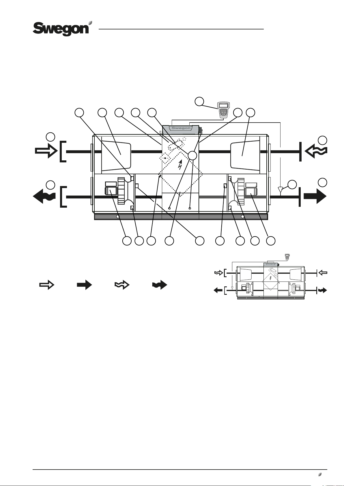
1.6.1 GOLD RX One-piece air handling unit with rotary heat exchanger
The specific components are outlined below each individually in a simplified and
schematic specification.
GB.GOLDSK509.091101
3 4 5 6
2
1
Right-hand version
Fig. 1a
7
8
9
11
10
12
14 15 16 17 18 19 20 21 2213
Outdoor air Supply air Extract air Exhaust air
GOLD 04-80: The air handling units can be ordered in the
right-hand version as shown in Fig. 1a or in the left-hand
version as shown in Fig. 1b.
GOLD 12-80: The air handling unit in Fig 1a shows Fan
Arrangement 1. The units can also be ordered with Fan
Arrangement 2; the fans and filters are then vertically
mirror-inverted.
In the left-hand version (Fig. 1b), the components marked
with an asterisk change function and designation (the
components are named according to whether they are for
supply air or extract air).
The location of the components and their designation
1 OUTDOOR AIR* (Left-hand version: Extract air)
2 EXHAUST AIR* (Left-hand version: Supply air)
3 Extract air fan* with motor and motor control system
4 Pressure transducer by extract air fan*
(Position on function selector switch = 1)
5 Pressure transducer by supply air filter*
(Position on function selector switch = 3)
Fig 1b
6 Electrical equipm. cubicle with control unit
7 Hand-held micro terminal
8 Extract air filter*
9 Adjustment plates (For left-hand version: by left-hand filter
section)
10 Supply air temp. sensor (to be mounted in supply air duct)
11 EXTRACT AIR* (Left-hand version: Outdoor air)
12 SUPPLY AIR* (Left-hand version: Exhaust air)
13 Supply air filter*
14 Outdoor temperature sensor*
15 Heat exchanger
16 Heat exchanger drive motor
17 Sensor for rotation monitor
18 Control unit for the heat exchanger
19 Pressure transducer by supply air fan*
(Position on function selector switch = 2)
20 Pressure transducer by extract air filter*
(Position on function selector switch = 4)
21 Extract air temperature sensor*
22 Supply air fan* with motor and motor control system
Left-hand version
4
www.swegon.com
We reserve the right to alter specifications without notice.
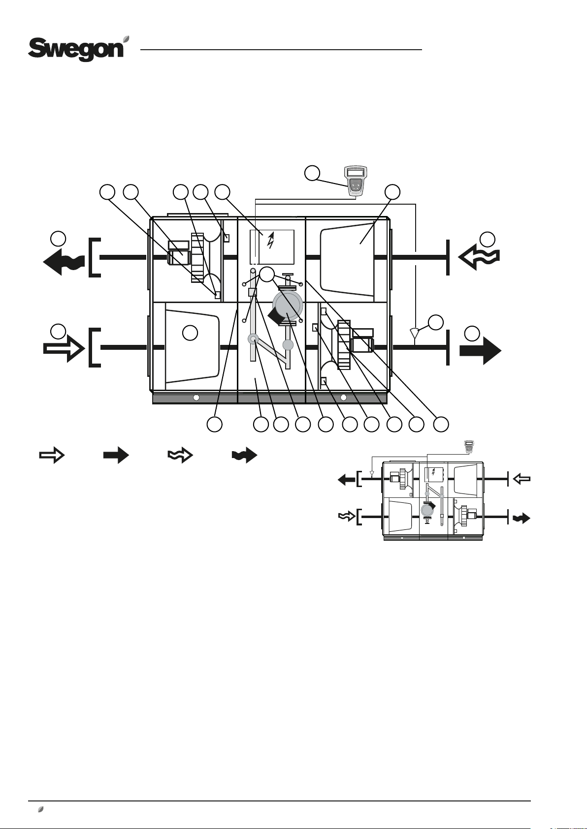
1.6.2 GOLD PX One-piece air handling unit with plate heat exchanger
The specific components are outlined below each individually in a simplified and
schematic specification.
8
GB.GOLDSK509.091101
3 6
2
1
Right-hand version
Fig. 2a
7 105 9
21
16
17 1918 2014415
2223
11
12
13
Outdoor air Supply air Extract air Exhaust air
The air handling units are supplied in the right-hand or
left-hand version as shown in Fig. 2a and 2b. In the lefthand version, the components marked with an asterisk
change function and designation (the components are
named according to whether they are for supply air or
extract air.).
The location of the components and their designation
1 EXHAUST AIR* (Left-hand version: Supply air)
2 OUTDOOR AIR* (Left-hand version: Extract air)
3 Pressure transducer by supply air filter*
(Position on function selector switch = 3)
4 Supply air filter*
5 Outdoor temperature sensor*
6 Electrical equipm. cubicle with control unit
7 Shut-off and by-pass valve actuator
8 Hand-held micro terminal
9 Temperature/relative humidity sensor in extract air*
Fig 2b
10 Extract air filter*
11 Supply air temp. sensor (to be mounted in supply air duct)
12 EXTRACT AIR* (Left-hand version: Outdoor air)
13 SUPPLY AIR* (Left-hand version: Exhaust air)
14 Extract air fan* with motor and motor control system
15 Pressure transducer by extract air fan*
(Position on function selector switch = 1)
16 Sensor for anti-frosting protection
17 Plate heat exchanger with by-pass and shut-off damper
18 Pressure transducer by supply air fan*
(Position on function selector switch = 2)
19 Pressure transducer by extract air filter*
(Position on function selector switch = 4)
20 Supply air fan* with motor and motor control system
21. Measurement tappings for measuring the pressure drop
across the heat exchanger.
22. Temperature/density sensor, supply air.
23. Temperature/density sensor, extract air.
Left-hand version
We reserve the right to alter specifications without notice.
www.swegon.com 5
1.6.3 GOLD CX One-piece air handling unit with coil heat exchangers
The specific components are outlined below each individually in a simplified
and schematic specification.
7
GB.GOLDSK509.091101
35 4 6
25
2
1
Right-hand version
Fan Arrangement 1
Fig. 3a
13
14 15 2019 2221
Outdoor air Supply air Extract air Exhaust air
23
8
11
10
12
1816 17
24
The air handling units can be ordered in the right-hand
version as shown in Fig. 3a or in the left-hand version as
shown in Fig. 3b.
The air handling unit in Fig. 3a shows Fan Arrangement
1. The units can also be ordered with Fan Arrangement 2;
the fans and filters are then vertically mirror-inverted.
In the left-hand version (Fig. 3b), the components marked
with an asterisk change function and designation (the
components are named according to whether they are for
supply air or extract air).
The location of the components and their designation
1 OUTDOOR AIR* (Left-hand version: Extract air)
2 EXHAUST AIR* (Left-hand version: Supply air)
3 Extract air fan* with motor and motor control system
4 Pressure transducer by extract air fan*
(Position on function selector switch = 1)
5 Pressure transducer by supply air filter*
(Position on function selector switch = 3)
6 Electrical equipm. cubicle with control unit
7 Hand-held micro terminal
8 Extract air filter*
10 Supply air temp. sensor (to be mounted in supply air duct)
Fig 3b
Left-hand version
Fan Arrangement 1
11 EXTRACT AIR* (Left-hand version: Outdoor air)
12 SUPPLY AIR* (Left-hand version: Exhaust air)
13 Supply air filter*
14 Outdoor temperature sensor*
15 Coil heat exchanger with pipework package
16 Valve actuator
17 Temperature sensor for anti-frosting protection
18 Circulation pump
19 Pressure transducer by supply air fan*
(Position on function selector switch = 2)
20 Pressure transducer by extract air filter*
(Position on function selector switch = 4)
21 Supply air fan* with motor and motor control system
22 Temperature/relative humidity sensor in extract air*
23. Measurement tappings for measuring the pressure drop
across the heat exchanger.
24. Temperature/density sensor, supply air.
25. Temperature/density sensor, extract air.
6
www.swegon.com
We reserve the right to alter specifications without notice.
GB.GOLDSK509.091101
2 SAFETY PRECAUTIONS
All staff concerned shall acquaint themselves with these
instructions before beginning any work on the unit.
Any damages to the unit or its components caused by
improper handling or misuse by the purchaser or the fitter
cannot be considered subject to guarantee if these instructions have not been followed correctly.
Warning
Only an authorised electrician or qualified service
personnel trained by Swegon shall be permitted
to modify the air handling unit in conjunction with
electrical installations or the wiring of external functions.
2.1 Safety Isolating Switch/Main Switch
Size 04/05, 08, 12, 14/20 and 25/30 one-piece GOLD
units with rotary (RX), plate (PX) or coil (CX) heat
exchanger: The safety isolating switch is located externally
on the junction hood.
Size 35/40, 50/60 and 70/80 one-piece GOLD units with
rotary heat exchanger (RX): The safety isolating switch is
externally located on the door of the centre section of the
unit.
Size 35/40 one-piece GOLD units with coil heat exchanger
(CX): The safety isolating switch is located on the left
side of the electric equipment cubicle in the centre section of the unit. Size 50/60 and 70/80 air handling units:
The safety isolating switch is located in a plastic enclosure
below the electrical equipment cubicle in the centre section of the unit.
Separate supply air and extract air handling units (SD): The
safety isolating switch is located on the inspection side by
the inspection door of the fan section.
The air handling unit shall normally be started and
stopped via the hand-held micro terminal, not via the
safety isolating switch.
Always switch off the safety isolating switch before servicing the unit if not otherwise specified in the pertinent
instructions.
2.2 Risks
Warning
Before carrying out any work, make sure that the
power supply to the unit has been isolated.
Risk areas with rotating parts
Moving parts are the fan impeller, drive pulleys of the
rotary heat exchanger, if fitted, and by-pass/shut-off
damper of the plate heat exchanger, if fitted.
The lockable inspection doors serve as protection from
contact with the fans and the heat exchanger. If the fan
outlets aren’t connected to any duct, they must be fitted
with a protective screen (wire mesh).
Warning
The inspection doors on the filter/fan sections must
not be opened while the unit is in operation.
Under normal operating conditions, use the stop
button on the hand-held terminal to stop the air
handling unit.
Wait until the fans have stopped rotating before
opening the inspection door.
The air pressure inside the filter/fan section is positive, which means that the door can fly open.
2.3 Safety Guards
The cover of the electric equipment cubicle serves as a
safety guard in the size 04/05 and 08 one-piece air handling units with rotary heat exchanger (RX), as well as
on all the other variants (PX/CX/SD). On size 12, 14/20,
25/30, 35/40, 50/60 and 70/80 one-piece air handling
units with rotary heat exchanger (RX), the lockable door
over the electrical equipment cubicle serves as a safety
guard.
Only a qualified electrician or trained service technicians
shall be allowed to remove the safety guards.
Warning
The power supply to the unit shall be isolated by
switching off the safety isolating switch before
removing the safety guard.
As long as the air handling unit is operating, the
safety guards must always be mounted, all inspection doors must be closed, and the junction hood
on the top of the unit must be mounted.
We reserve the right to alter specifications without notice.
2.4 Glycol
Glycol is used in the GOLD air handling units with
coil heat exchanger. Never pour glycol down a
drain; collect it in a receptacle and leave it at a
recycling centre, petrol station, or the like. Glycol
is highly dangerous to consume and can cause
fatal poisoning or damage the kidneys. Contact a
doctor! Avoid breathing glycol vapour in confined
spaces. If you get glycol in your eyes, flush them
thoroughly with water (for about 5 minutes). If
glycol splashes on your skin, wash with soap and
water.
www.swegon.com 7
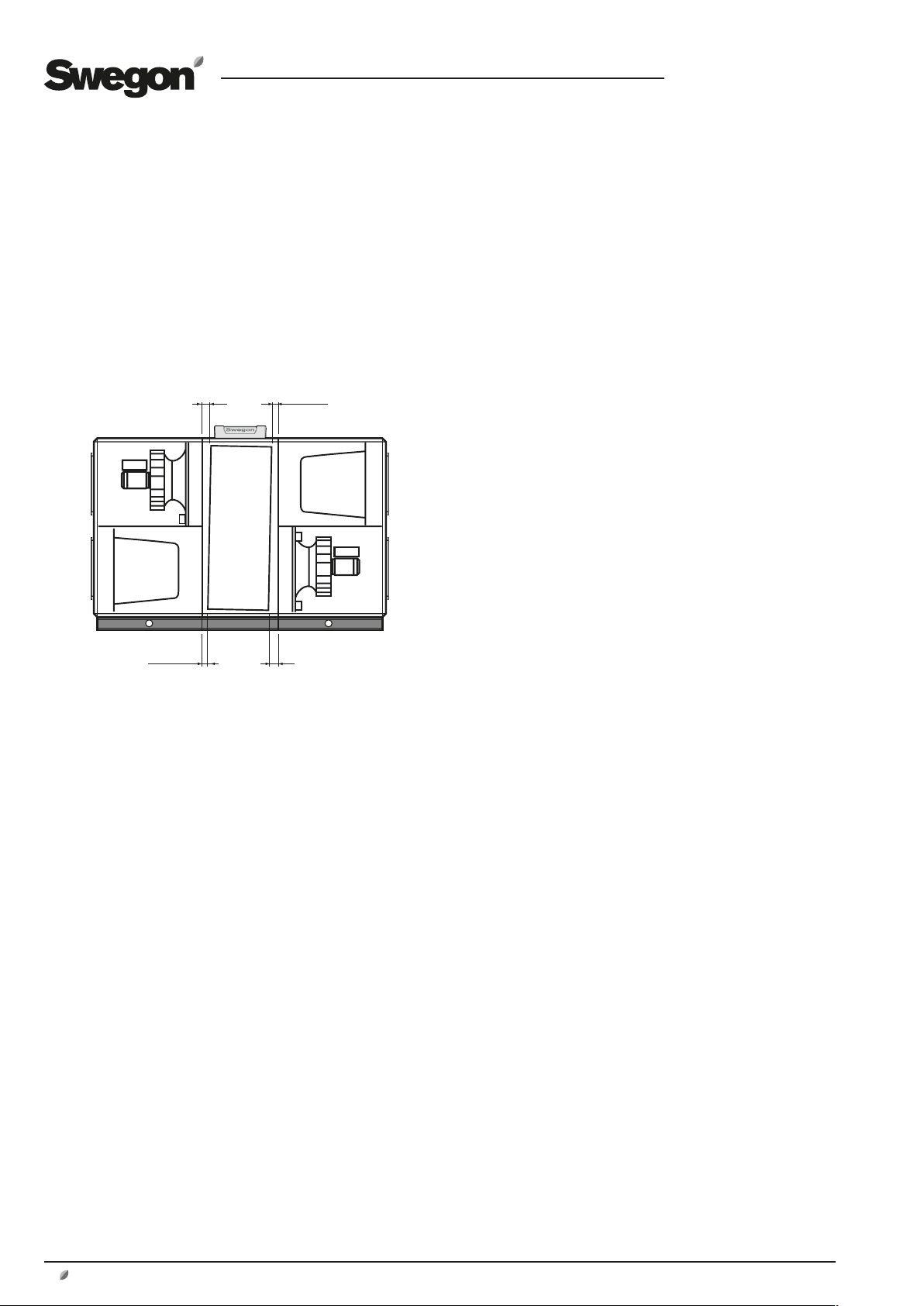
3 COMMISSIONING
L
L
≈ 0,5xL
≈ 0,5xL
3.1 General
Sequence for commissioning:
1. Check that there are no foreign objects in unit, ducting system
or functional sections.
2. Check that rotating heat exchangers (only GOLD RX) rotate
easily. On sizes 50-80, the rotating heat exchanger must be
angled slightly towards the filter, see diagram below.
If the angle needs adjusting, see special instructions for angle
adjustment, rotating heat exchangers.
GB.GOLDSK509.091101
GOLD RX,, sizes 50-80: The illustration shows the factorypreset rotor inclination in a unit with Fan Arrangement 1.
The inclination must always be towards the filter, which
means that the inclination for Fan Arrangement 2 is in the
other direction.
3. Turn the safety isolating switch to the ON position (I).
4. Select the language desired, if you have not already done so.
See Section 5.2 or 13.1.
5. The unit has factory settings which make it ready to use. See
Section 19.2 Commissioning record.
However, in many cases, these settings need to be adjusted to
suit the current installation.
Program the switch clock, operating conditions, temperatures,
airflows and functions according to the procedures in Sections
4-15.
Select whether l/s, m3/s or m3/h shall be used as the flow unit.
(INSTALLATION LEVEL in the HAND-HELD MICRO TERMINAL
menu).
Fill out the Commissioning Record and save it in the document
pocket of the unit.
6. Activate, if needed, manual or auto operation (MAIN MENU)
or lock the speed of the fans (AIR ADJUSTMENT menu).
Adjust the ducting system and air devices as described in Section
3.2.
7. Check and adjust, if required, the pressure balance in the unit
as described in Section 3.3.
8. Finish off with a filter calibration as described in Section 6.4.2.
8
www.swegon.com
We reserve the right to alter specifications without notice.

GB.GOLDSK509.091101
3.2 Adjusting the Duct System
and Air Devices
In order to prevent the fans from consuming more power
than necessary, it is important to keep the pressure drop in
the system as low as possible.
It is also important that ducting systems and air devices are
correctly adjusted to provide the comfort expected.
When adjusting air devices and the duct system installed
in combination with the GOLD, it is appropriate to follow
the proportionality method.
This means that the proportion between the airflows in
branch ducts stays constant even if the airflow in the main
ducts is changed. The same proportion applies to the air
devices in the installation.
When adjusting the ducting system there is provision
for locking the speed of the fans in the unit to a specific
preset flow rate, see Section 6.5.
3.2.1 Adjustment Sequence
The system should be adjusted in the following order:
1. Adjust of the air devices in each branch duct.
2. Adjust the branch ducts.
3. Adjust the main ducts.
3.2.2 Adjustment Procedure
1. Set all the air devices and dampers to the fully open
position.
2. Calculate the ratio of the airflow reading to the design
airflow of all the air devices, branch ducts and main ducts.
The air device in every branch that has the lowest ratio
should be fully open. Use this air device as an INDEX AIR
DEVICE. The same applies to branch dampers and main
dampers.
When you’ve completed the adjustments, one air device in
every branch, one branch damper and one main damper
should consequently be fully open.
3. Start adjusting the main duct that has the highest ratio
and the branch duct in the main duct that has the highest
ratio. Starting from this point enables you to “press” the
air in front of you toward the sections of the system that
have the least air.
4. Adjust the last air device on the duct branch so that
it will have the same ratio as the index device. This air
device will serve as the REFERENCE AIR DEVICE. Often
it is the last air device on the branch that has the lowest
ratio and should be open. In this case, the same air device
serves as the index device and reference device.
5. Throttle the other air devices in the branch to the same
ratio as the reference device.
Note! The ratio in the reference device will change every
time another air device is throttled, so in practice the ratio
for the reference device can be set slightly higher. The
reference device must be measured in between each air
device throttled.
6. Go to the branch that had the next highest ratio and
adjust the air devices there, etc.
Note! All branch dampers should be fully open until all air
devices have been adjusted.
7. Throttle the branch damper that had the highest ratio
to the same ratio that the branch of the lowest ratio had.
Note! Keep in mind that the index damper changes ratio;
proceed as described in item 5.
8. When all branches have been adjusted, throttle the
main dampers in the same manner.
Also see the example below on how to carry out adjust-
ments.
Example on how to carry out adjustments
– Start adjusting duct branch B, since this one has
the highest ratio.
– The last air device, B3, has the lowest ratio and
should be fully open.
Adjust the other air devices, B1 and B2, so that
these will have the same ratio as air device B3 (see
item 5 above).
– Now adjust the air devices in branch duct C. Air
device C4 should be fully open; throttle the others
to the same ratio.
– Adjust the air devices in branch duct A. The index
air device here is air device A3, which means that
you first throttle air device A4 (the reference device)
to device A3:s ratio.
Thereafter the others are adjusted to the same ratio
as air device A4.
– Throttle branch damper B to the same ratio as branch damper A,
throttle branch damper C to the same ratio as branch damper A.
Check that all dampers have the same ratio.
When the adjustment has been completed, 3 air devices and one
branch damper should stand fully open to obtain the lowest possible pressure in the system.
We reserve the right to alter specifications without notice.
qp = design airflow (l/s)
qm = airflow reading (l/s)
q
K (Ratio) =
q
m
p
www.swegon.com 9
GB.GOLDSK509.091101
3.3 To Adjust the Pressure Balance
(applicable to air handling units with rotary heat
exchanger)
3.3.1 General
The pressure in the extract airflow path should be slightly
lower than that in the supply airflow path to ensure correct air leakage direction and that the purging sector in
the heat exchanger will work correctly. This ensures that
extract air will not be carried over to the supply air.
The pressure balance in the unit should be adjusted when
the ventilation system has been fully installed, all the air
devices have been adjusted and the supply air and extract
air flows are as they should be while the air handling unit
is operating normally.
Adjustment plates
GOLD RX 04-12 GOLD RX 14-80
1-2 plates 1-5 plates
CLOSE OPEN
several adjustment plates)
OPEN (Take out adjustment plates)
GOLD RX Top 12
1 plate, left-hand
version
EXTRACT AIR
CLOSE
(Push in one or
GOLD RX Top 12
1 plate, right-hand
version
EXTRACT AIR
10
www.swegon.com
Fixing screw
Flow adjustment plate Flow adjustment plate
Two flow adjustment plates are supplied with the GOLD RX Top.
The version of the air handling unit, i.e. right-hand or left-hand,
is the factor that determines which of the flow adjustment
plates you should install in the unit. Install the correct flow
adjustment plate at its intended location inside the air handling
unit. Scrap the other plate. See the illustration above.
Remove the fixing screws and place the flow adjustment plate in
the grooves intended for retaining it. Tighten the fixing screws.
See the illustration above.
The pressure balance can be adjusted by blanking off holes in
the flow adjustment plate with the plugs supplied with the unit.
We reserve the right to alter specifications without notice.
Fixing screw

GB.GOLDSK509.091101
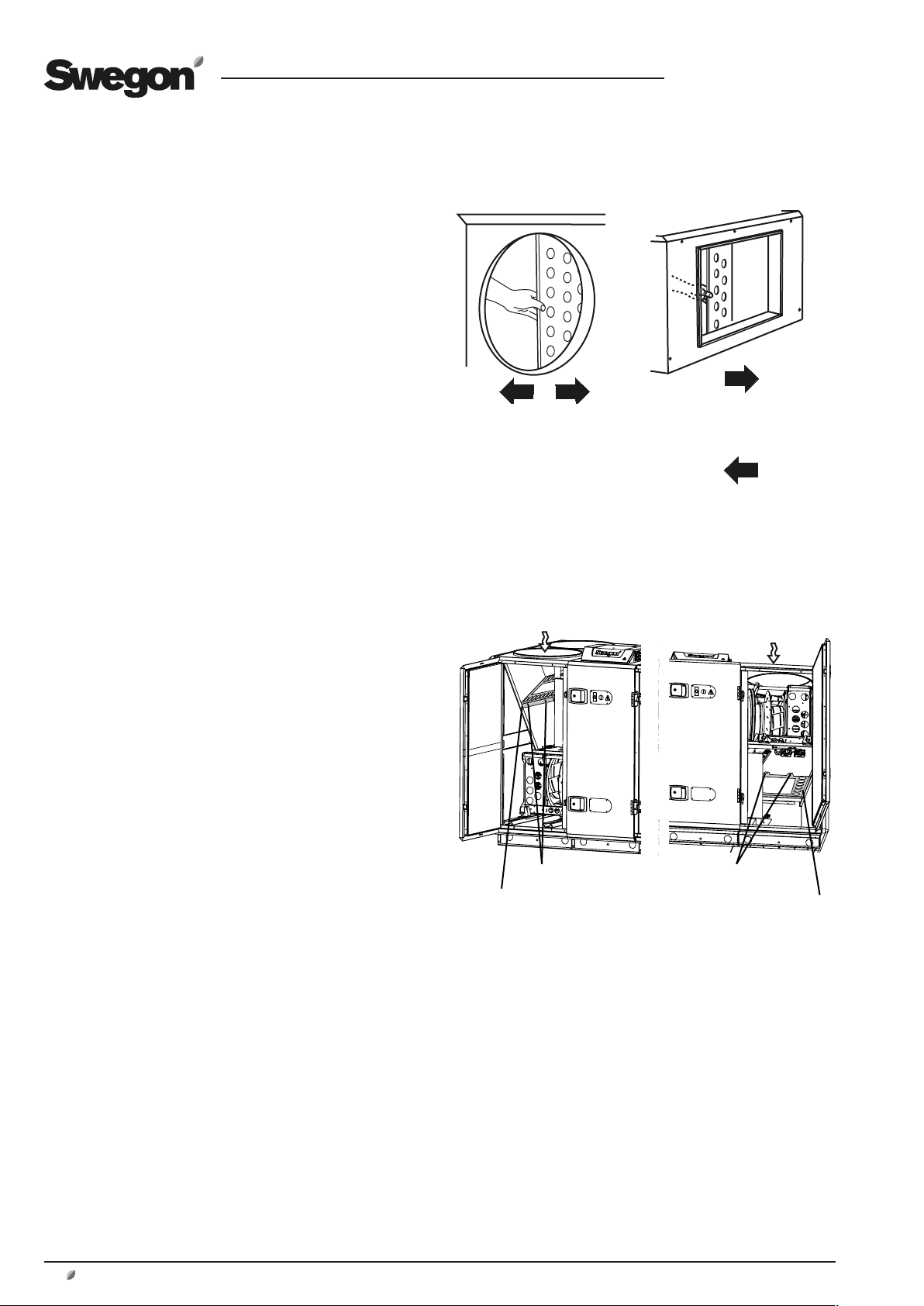
3.3.2 To Ensure the Correct Leakage Direction
The adjustment plates fitted in the extract air inlet are
used for adjusting the pressure balance in the unit. The
adjustment plates are supplied separately and should be
fitted in the unit by the fitter when he connects the extract
air ducting to the air handling unit. See the illustrations on
the previous page.
Connect a pressure gauge to the pressure measurement
tappings of the unit.
The unit has four pressure measurement tappings; the two
closest to the extract air duct should be used. The blue
pressure measurement tapping measures the negative
pressure in the extract air section and the white pressure
measurement tapping measures the negative pressure in
the supply air section.
On the size 04-08 units, the pressure measurement tappings are by the junction hood and on the size 12-80 units
they are inside in the centre section of the unit.
See illustration to the right.
Note that both pressure measurement tappings measure
negative pressure.
MEASURED VALUES
The negative pressure in the extract air section should be
greater or the same as the one in the supply air section.
If the negative pressure in the extract air section is the
same or up to 20 Pa more than the negative pressure in
the supply air section, then you’ve finished this adjustment.
Pressure measurement nipples -
leakage direction
(Unit in right-hand version)
- (blue)
+ (white)
GOLD 04-08
EXTRACT AIR
– (blue)
+ (white)
GOLD 12-80
EXTRACT
AIR
DEVIATIONS
If the negative pressure in the extract air section is less
than that in the supply air section, the adjustment plates
must be readjusted as follows:
1. Stop the unit, open the inspection door to the extract
air filter.
GOLD RX Top: blank off a number of holes in the flow
adjustment plate with the plastic plugs supplied with the
unit.
Other models: slightly push the flow adjustment plates
forward (close them) in the extract air intake opening.
For full face connection (duct accessory in insulated
casing): If the commissioning plate(s) is/are completely
closed and the sub-atmospheric pressure in the extract air
section is still less than in the supply air section, blank off
a number of holes in the commissioning plate with the
plastic plugs supplied.
3. Close the inspection door and restart the unit.
4. Measure the pressures.
Repeat until the negative pressure in the extract air section
is the same or up to 20 Pa higher than the negative pressure in the supply air section (0–20 Pa).
5. If the negative pressure in the extract air section is
higher than 20 Pa compared to the supply air section,
although the adjustment plates are completely open, the
leakage and purging air flow will be more than anticipated. This means that the actual extract air flow will deviate
from the preset extract airflow. The deviation increases
with increased pressure differential.
We reserve the right to alter specifications without notice.
www.swegon.com 11
4 HAND-HELD MICRO TERMINAL
AND HOW TO USE THE MENUS
GB.GOLDSK509.091101
4.1 HAND-HELD MICRO TERMINAL
4.1.1 General
The hand-held micro terminal consists of an encapsulated
control box with a 3-metre long cable for connection to
the air handling unit by means of a quick connector.
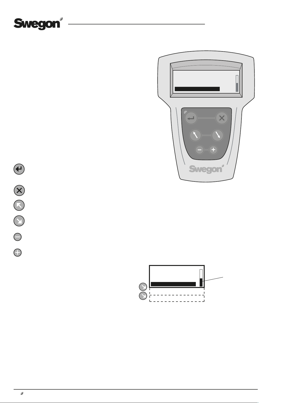
The hand-held terminal has an illuminated display, 6 pushbuttons and a red LED for indicating alarms.
4.1.2 Buttons
The buttons have the following functions:
ENTER confirms your selection and proceeds to next
menu level.
ESCAPE reverts to the previous menu.
ADVANCE UPWARD or to the LEFT.
GOLD TUE 14:40
STOP
MANUAL OPERATION
STOP?
ADVANCE DOWNWARD or to the RIGHT.
DECREASES the value of the highlighted setting.
INCREASES the value of the highlighted setting.
4.3.1 Display Screen
The display screen has 4 lines. Many of the menus however have several lines and these are shown line for line as
you press the ADVANCE DOWNWARD button. The position indicator shows where you are in the menu.
4.1.4 Abbreviations
The following abbreviations are used in the menus
SA = Supply air (E.g. SA FAN = Supply air fan)
EA = Extract air
OUTD = Outdoor air
FV = Anti-frosting monitor
HEAT EXCH = Heat exchanger
GOLD TUE 14:40
STOP
MANUAL OPERATION
STOP?
MAN/AUTO.OP
SETTINGS
Position indicator
12
www.swegon.com
We reserve the right to alter specifications without notice.
GB.GOLDSK509.091101
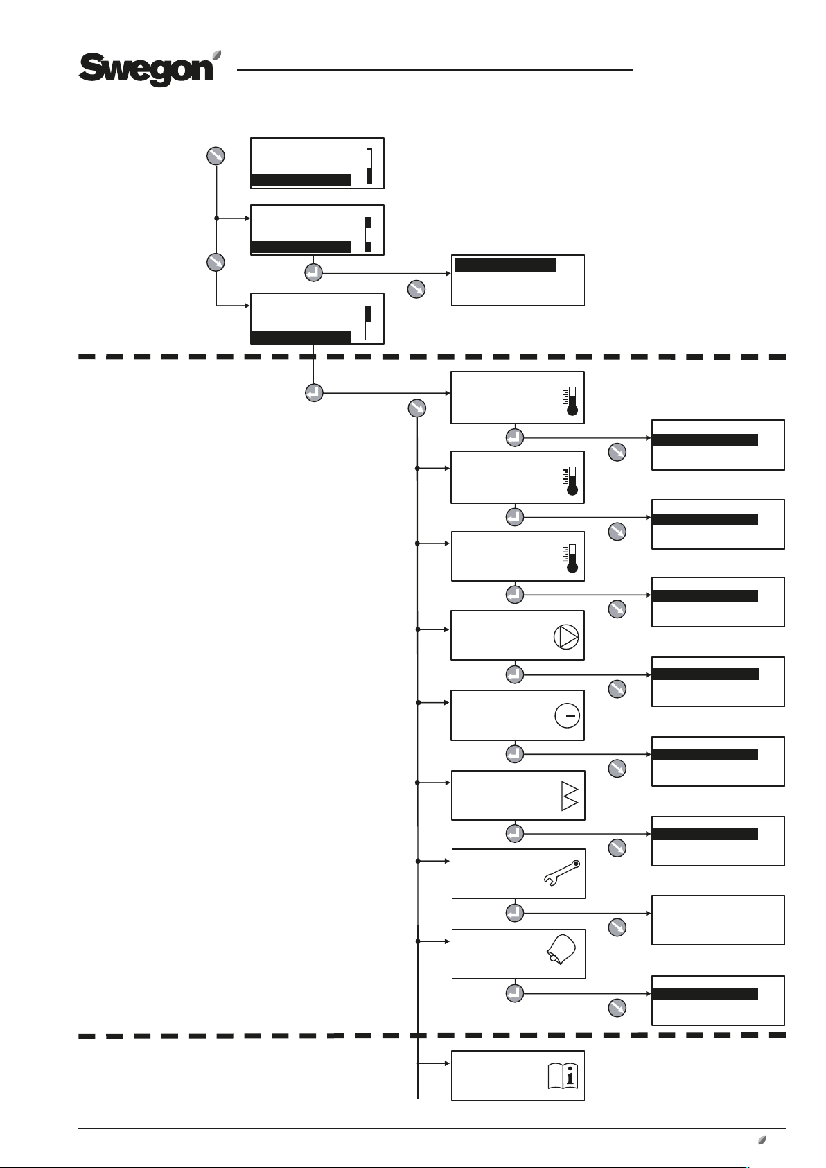
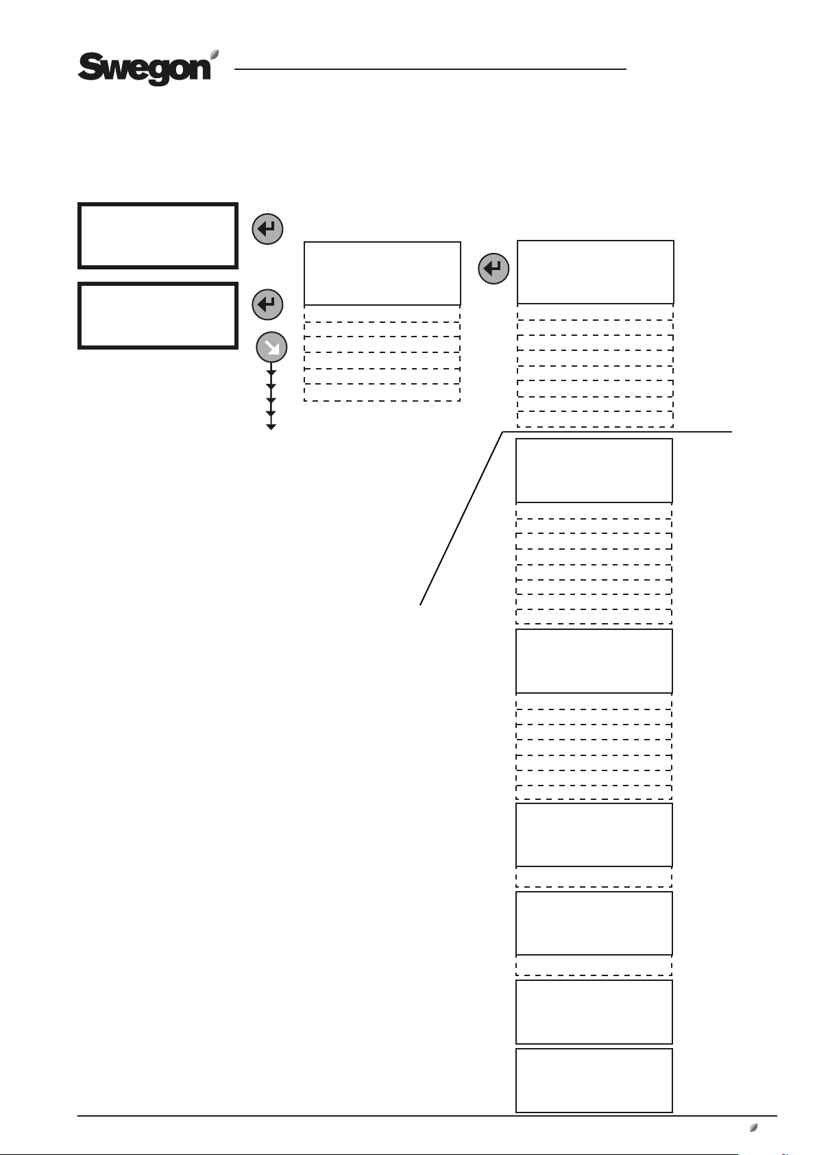
4.2 Menu Tree
MAIN
MENU
(Section 5)
USER LEVEL
(Section 6)
GOLD RX TUE 14:40
STOP
MANUAL OPERATION
STOP?
GOLD RX TUE 14:40
MANUAL OPERATION
STOP?
MAN/AUTO.OP
GOLD RX TUE 14:40
STOP?
MAN/AUTO.OP
SETTINGS
AUTO OPERATION
MANUAL LOW SPEED
MANUAL HIGH SPEED
TEMPERATURE
ALL YEAR COMFORT
Xzone
Important! The appearance of
the menus varies depending
on the type of air handling
unit and functions selected.
*TEMPERATURE*
READINGS
SETTINGS
*ALL YEAR COMFORT*
READINGS
SETTINGS
FLOW/PRESSURE
SWITCH CLOCK
FILTERS
AIR ADJUSTMENT
ALARMS
*Xzone*
READINGS
SETTINGS
*FLOW/PRESSURE*
READINGS
SETTINGS
*SWITCH CLOCK*
TIME/DATE
TIME CHANNEL
YEAR CHANNEL
*FILTERS*
READINGS
CALIBRATION
*AIR ADJUSTMENT*
LOCKS FAN SPEED
TIME SETTING: 0 h
*ALARMS*
ACTIVE ALARMS
ALARM HISTORY
INSTALLATION LEVEL
(Section 7-15)
We reserve the right to alter specifications without notice.
INSTALLATION
www.swegon.com 13
GB.GOLDSK509.091101
5 MAIN MENU
5.1 General
The main menu is normally shown if no other menu
has been selected.
The display automatically returns to the main menu
after 30 minutes.
The content in the menu changes depending on the
operating mode selected other functions that affect
the present operating mode and possible tripped
alarms.
5.2 Selection of Language
When the air handling unit is started up for the first
time, a language selection menu is displayed.
Select the language desired.
If you want to change language at a later oppor-
tunity – or if you’ve selected the wrong language
– you can change the language at INSTALLATION
LEVEL under HAND TERMINAL. See Section 13.1.
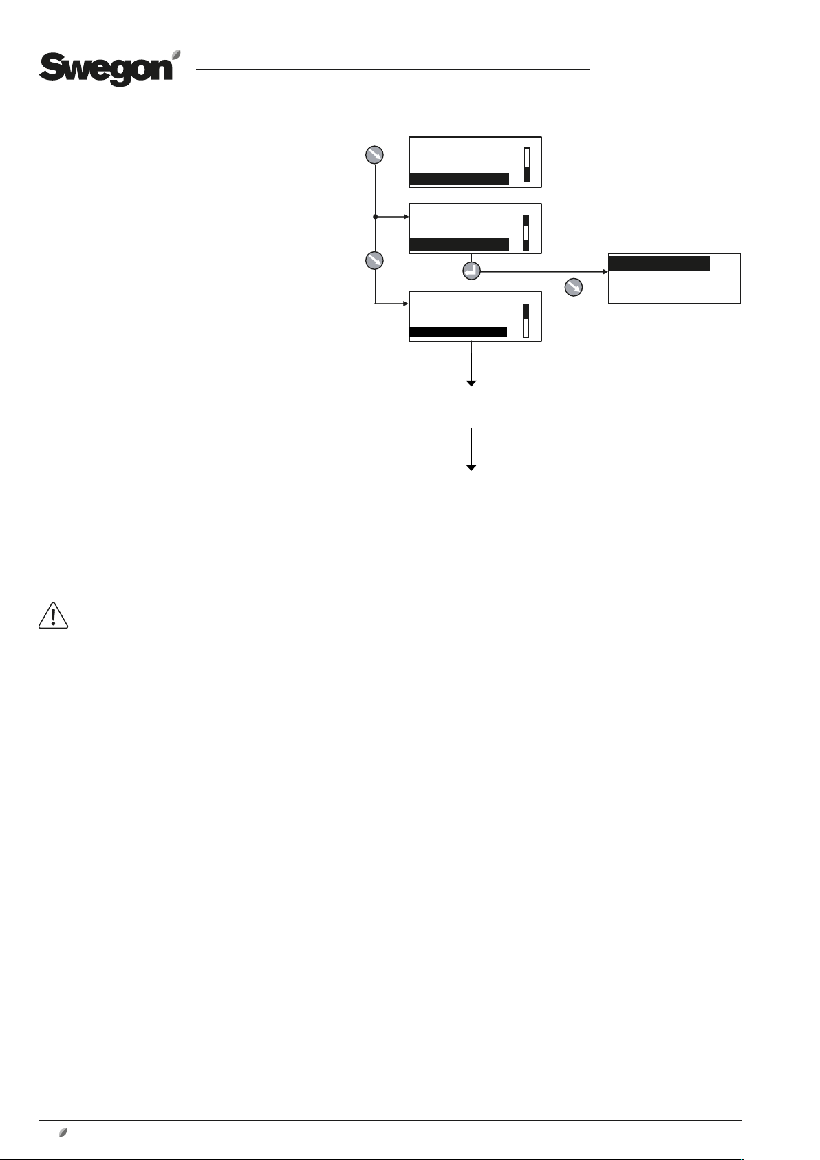
5.3 Changing Operating Mode
You can start and stop the air handling unit or
change over to manual or automatic operation
from the main menu.
The air handling unit should normally be
started and stopped from the hand-held
micro terminal; not by switching the safety
isolating switch on and off.
When the air handling unit is started up, menus
for the various delays that are part of the starting
sequence are shown.
See also Section 9.1.1, Starting Sequence.
GOLD RX TUE 14:40
STOP
MANUAL OPERATION
STOP?
GOLD RX TUE 14:40
MANUAL OPERATION
STOP?
MAN/AUTO.OP
AUTO OPERATION
MANUAL LOW SPEED
MANUAL HIGH SPEED
GOLD RX TUE 14:40
STOP?
MAN/AUTO.OP
SETTINGS
USER LEVEL
INSTALLATION LEVEL
5.4 Settings
When selecting SETTINGS in the main menu, you
will advance to User Level and Installation Level.
See Section 6.
14
www.swegon.com
We reserve the right to alter specifications without notice.
GB.GOLDSK509.091101
1
2
3
15
20
22
9
10
12 15 20 25 27
15
10
20
12 15 20 25
6 USER LEVEL
6.1 Temperature
The basic functions can be preset at INSTALLATION
LEVEL and the values can be read and set at USER
LEVEL.
See also Section 8.2 in which the functions for
temperature are described in detail.
IMPORTANT! If you intend to substantially alter the tempera-
ture settings, you should first stop the air handling unit before
doing so.
If only GOLD SD supply air handling units are installed, they
require an external room sensor for ERS and extract air control.
6.1.1 Readings
Used for checking the performance.
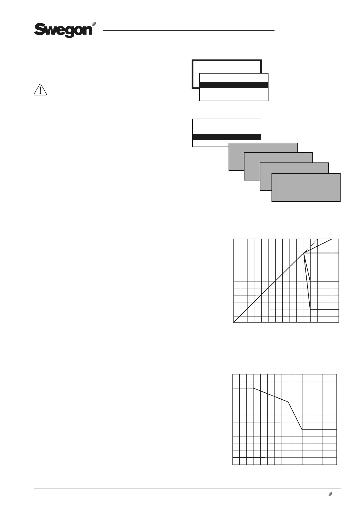
6.1.2 Settings
ERS REGULATION 1
The control unit regulates the relationship between the supply
air and the extract air temperatures according to a factory
preset curve.
Settings (see the chart to the right as well):
Value Setting Factory
range settings
Step 1 - 4 2
EA/SA Differential 1-5 °C* 3 °C
Breakpoint (refers to 15-23 °C* 22 °C
extract air temperature)
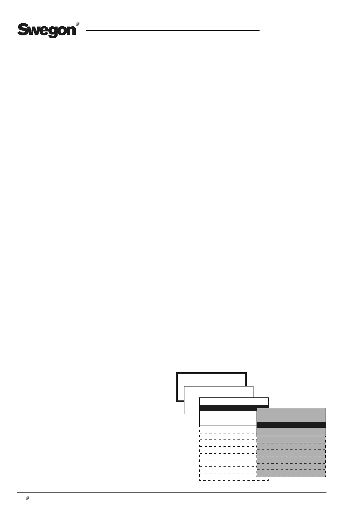
TEMPERATURE
*TEMPERATURE*
READINGS
SETTINGS
*TEMPERATURE*
READINGS
SETTINGS
ERS Regulation 1
ERS REGULATION 1
ERS REGULATION 2
SUPPLY AIR REG.
Important! The
appearance of the
menus varies depending
on the type of air
handling unit and
functions selected.
EXTRACT AIR REG.
Breakpoint
Step 1
Step 2
ERS REGULATION 2
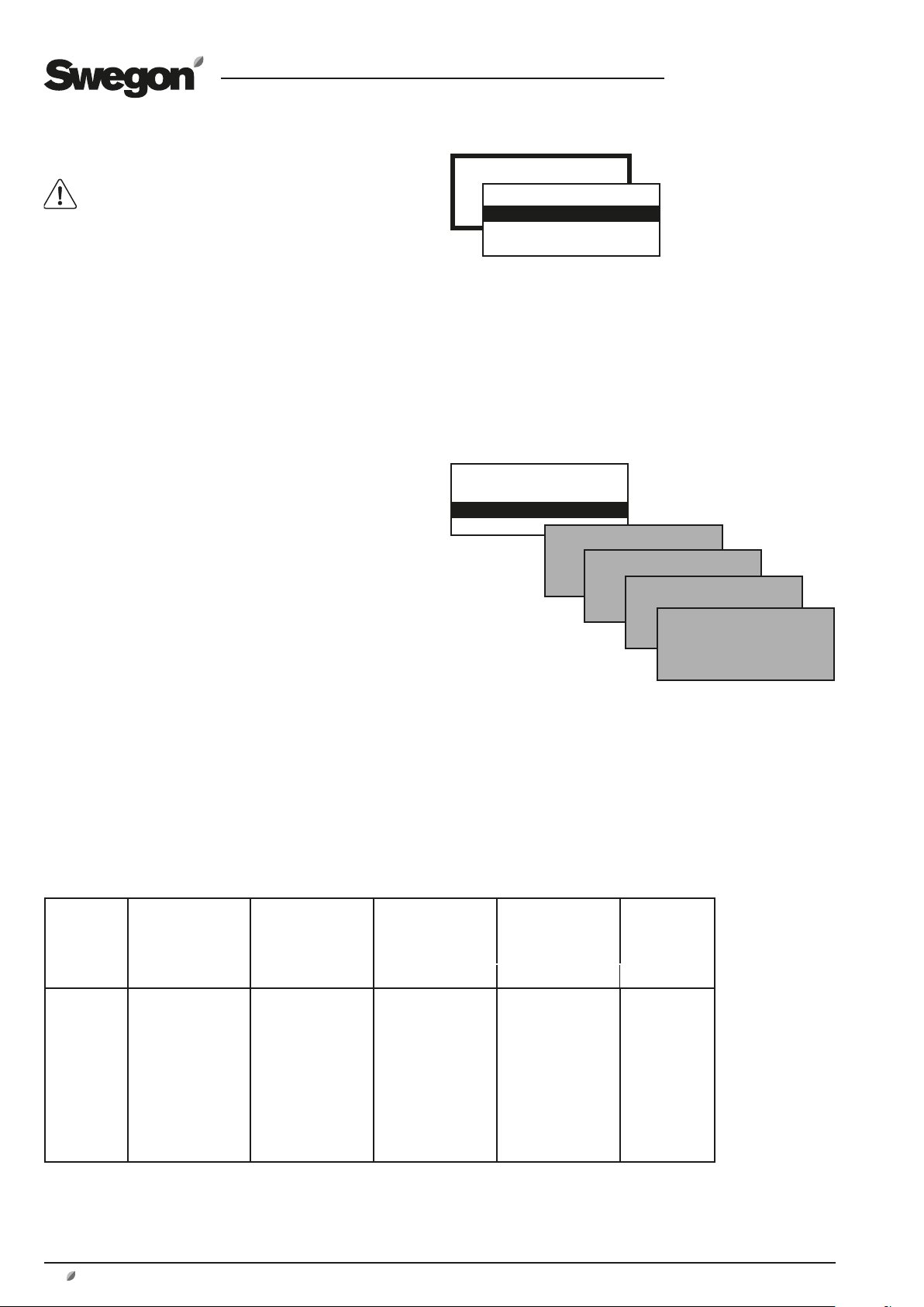
The control unit regulates the relationship between the supply
air and extract air temperatures according to a custom-plotted
curve. The curve has three adjustable breakpoints.
Settings (see the chart to the right as well):
Value Setting Factory
range settings
Extract air temperature
X1 10-40 °C 15 °C
X2 10-40 °C 20 °C
X3 10-40 °C 22 °C
Supply air temperature
Y1 10-40 °C 20 °C
Y2 10-40 °C 18 °C
Y3 10-40 °C 14 °C
SUPPLY AIR REG.
Settings:
Value Setting Factory
range settings
Supply air temperature
setpoint 15-40 °C* 21.5 °C
EXTRACT AIR REG.
Settings:
Value Setting Factory
range settings
Extract air/room temp.
Setpoint 15-40 °C* 21.5 °C
Min. supply air temperature 13-25 °C* 15 °C
Max. supply air temperature 18-45 °C* 28 °C
*) The setting range can be changed. See 13.3, Min/Max Adjustment.
We reserve the right to alter specifications without notice.
EA/SA differential
Supply air temperature setpoint °C
Extract air temperature °C
ERS Regulation 2
Y = Supply air temperature setpoint °C
X = Extract air temperature °C
Step 3
Step 4
www.swegon.com 15
GB.GOLDSK509.091101
6.2 Air flow/Pressure
Basic functions are set at INSTALLATION LEVEL
and values are read and set at USER LEVEL.
Therefore see also Section 8.3, in which the func-
tions for flow/pressure are described in detail.
6.2.1 Readings
Used for performance checks.
6.2.2 Settings
The functions selected at INSTALLATION LEVEL and the
min. and max. airflows of each unit size (see the table
below) determine which values can be set.
Values for airflow (l/s, m3/s, m3/h), pressure (Pa) or input
signal strength (%) can be preset depending on the function selected.
LOW SPEED
Must always be preset! The value for low fan speed
cannot be higher than the value for high speed. Low
speed can be set to 0, which means that the fan is standing still.
HIGH SPEED
Must always be preset! The value or pressure for high fan
speed cannot be lower than the value for low fan speed.
AIR FLOW/PRESSURE
*FLOW/PRESSURE*
READINGS
SETTINGS
*FLOW/PRESSURE*
READINGS
SETTINGS
LOW SPEED
HIGH SPEED
MAX. SPEED
MIN/MAX. SPEED
MAX SPEED
Max speed is only appropriate for functions such as pressure regulation, flow boost, Heating BOOST or Cooling
BOOST. The value for max fan speed cannot be lower than
the value for high fan speed.
MIN/MAX SPEED
Min/max fan speed is only appropriate for demand-controlled operation. The lowest and highest permissible
flows are preset for each of the fans. This means that the
fans will not operate outside these limits, regardless the
load.
Min/Max Airflows
AIRFLOW MIN. FLOW, ALL
SIZE
GOLD 04 288 0.08 1620 0.45 1620 0.45 25 0.01
GOLD 05 288 0.08 2340 0.65 2340 0.65 25 0.01
GOLD 08 720 0.20 3600 1.00 3600 1.00 25 0.01
GOLD 12 720 0.20 5040 1.40 5040 1.40 25 0.01
GOLD 50 3600 1.00 18000 5.00 18000 5.00 100 0.05
GOLD 60 3600 1.00 23400 6.50 23400 6.50 100 0.05
GOLD 70 5400 1.50 27000 7.50 27000 7.50 100 0.05
GOLD 80 5400 1.50 34200 9.50 34200 9.50 100 0.05
VARIANTS
m3/h * m3/s m3/h m3/s m3/h m3/s m3/h m3/s m3/h m3/s
MAX FLOW
ONE-PIECE UNIT
ROTARY HEAT
EXCH. (RX)
MAX FLOW
ONE-PIECE UNIT
PLATE HEAT EXCH.
(PX)
MAX FLOW
ONE-PIECE UNIT
COIL HEAT EXCH.
(CX)
SMALLEST
STEP
* When entering settings, round off the values to the
nearest adjustable step.
** Air handling unit incl. coil heat exchanger may give
rise to a lower max. flow.
16
www.swegon.com
We reserve the right to alter specifications without notice.
GB.GOLDSK509.091101
6.3 Switch clock
Basic functions for the switch clock can be preset
at INSTALLATION LEVEL under FUNCTIONS/OPERATION and the values can be read and set at USER
LEVEL.
TIME/DATE
The current date and time can be set and adjusted whenever
required.
The switch clock automatically takes leap years into consideration.
Automatic changeover between summer time/winter time to EU
Standard has been preset.
This changeover function can be blocked at INSTALLATION LEVEL
under FUNCTIONS/OPERATION.
TIME CHANNEL
Times and days can be set when the unit is to run at high speed,
low speed or be stopped.
Eight different time channels can be set. If the same in-operation
times are to apply every day of the week (Mon-Sun), you need
only program one time channel. Different operation times for
each day of the week can be programmed by programming a
time channel for each day (Mon-Fri, Sat-Sun or Mon, Tues, Wed,
etc)
The time can be set as 00:00-00:00 if the deviating in-operation
period is desirable for the entire 24 hours period.
YEAR CHANNEL
The year channels make it possible to set deviating in-service
times for parts of the day during certain parts of the year. Eight
different year channels (yearly time schedules) can be set. The
year channels over-modulate the time channel during the hours
of the day and the days that the year channel is active. The year
channel dates indicate the dates between which the year channel shall apply and the year channel hours indicate the hours of
the day between which the year channel will steer the controller
to operate the rotary heat exchanger at a specified speed. Other
times within the year channel still apply to that time channel.
The time can be set as 00:00-00:00 if the deviating in-operation
period is desirable for the entire 24 hours period.
Functions for summer night cooling, prolonged operation, etc.,
operate also when the year channel is active.
6.4 Filters
(and anti-frosting function of rotary heat exchanger)
6.4.1 Readings
When reading of filter status the first value shows current pressure and the second value shows current alarm limit.
6.4.2 Calibration - Filters
The filters should be calibrated for the first time in conjunction
with commissioning, when the duct system, air devices and
eventual adjustment plates have been fitted and adjusted; after
that every time the filter media are changed.
Calibration should be activated for both the supply air and the
extract air if both filters are changed or for only for one airflow
direction if only one filter has been changed.
When filter calibration is enabled, the air handling unit operates
in the high speed or max. speed mode (depending on the functionality selected) for approx. 3 minutes.
SWITCH CLOCK
*SWITCH CLOCK*
TIME/DATE
TIME CHANNEL
YEAR CHANNEL
Settings:
Value Setting Factory
range setting
TIME/DATE
Day Mon-Sun Automatic
Time 00:00-23:59 Current
Date Day/Month/Year Current
TIME CHANNEL 1-8
Operation Low speed/High speed* High speed
Time 00:00-23:59 00:00-00:00
Period Not active Not active
Mon, Tues, Wed etc
Mon-Fri
Mon-Sun
Sat-Sun
YEAR CHANNEL 1-8
Operation Not active Not active
Stop/Low sp./High sp.
Time 00:00-23:59 00:00-00:00
Period From Day/Month/Year 01/01/2005
To Day/Month/Year 01/01/2005
*) Shows Stop/Low speed/High speed if this function is selected
at INSTALLATION LEVEL under FUNCTIONS/OPERATION.
FILTERS
*FILTERS*
READINGS
CALIBRATION
*FILTERS*
READINGS
CALIBRATION
After the filters have been calibrated, a pressure rise of up to 100
Pa is permissible (=as the filters arrest impurities). Higher pressure
will cause the fouled filter alarm to trip.
The alarm limit can be changed at INSTALLATION LEVEL under
ALARM SETTINGS.
The filter function must be activated in order to make it possible to obtain filter calibration and alarm functions in GOLD SD
supply air and extract air handling units, see Section 8.4, Filters.
*FILTER CALIBRATION*
STD.FILTER
PREFILTER
HEAT EXCHANGER
6.4.3 Calibration - Rotary Heat Exchanger
If the anti-frosting function accessory for heat exchanger
is installed (see 8.5.1.1) calibration can be selected from
this menu.
When calibration R-HX is activated the fans are accelerated to high speed for about 3 minutes.
We reserve the right to alter specifications without notice.
www.swegon.com 17
GB.GOLDSK509.091101
6.5 Air Adjustment
The speed of the fans can be locked for up to 72 hours.
This is practical when making air adjustments in the duct
system and air devices.
The period desired is preset but can be interrupted earlier
by selecting STOP in the menu or by changing the time
setting to 0.
6.6 Alarms
If an alarm is initiated, this is shown in the hand-held terminal both as clear text and by a blinking red diode.
This menu enables you to read alarms quickly.
ACTIVE ALARMS
Shows alarms that are active but have not initiated an
alarm signal in the display. This applies to alarms that have
a long delay, i.e. airflow or temperature alarms.
ALARM HISTORY
The 10 most recent tripped alarms are shown.
AIR ADJUSTMENT
*AIR ADJUSTMENT*
LOCKS FAN SPEED.
TIME SETTING: 0 h
ALARMS
*ALARMS*
ACTIVE ALARMS
ALARM HISTORY
Alarm settings can be entered at INSTALLATION
LEVEL under ALARM SETTINGS.
For complete description of alarms, see Section 17.
18
www.swegon.com
We reserve the right to alter specifications without notice.
GB.GOLDSK509.091101
7 INSTALLATION LEVEL
7.1 Menu Survey
INSTALLATION
*INSTALLATION*
CODE: 0000
Code = 1111
Automatic functions
FUNCTIONS
READINGS
MANUAL TEST
ALARM SET
HAND TERMINAL
COMMUNICATION
SERVICE LEV.
Section 9
Important! The appear-
ance of the menus varies
depending on the type
of air handling unit and
functions selected.
*FUNCTIONS*
TEMPERATURE
AIR FLOW/PRESSURE
FILTER
OPERATION
HEATING
COOLING
HUMIDITY
ReCO
2
IQnomic Plus
ALL YEAR COMFORT
CONTROL Optimize
*READINGS*
TEMPERATURE
FANS
HEAT EXCHANGE
REGULATION SIGNALS
IN/OUTPUTS
HUMIDITY
ReCO
2
IQnomic Plus
ALL YEAR COMFORT
OPERATION TIME
PROGRAMVERSIONS
*MANUAL TEST*
TEMPERATURE
FANS
HEAT EXCHANGE
REHEAT
EXTRA REG.SEQ.
COOLING
IN/OUTPUTS
ReCO
2
IQnomic Plus
ALL YEAR COMFORT
*ALARM SETTINGS*
FIRE ALARM
EXTERNAL ALARMS
ALARM LIMITS
ALARM PRIORITY
*HANDTERMINAL SET*
LANGUAGE
AIR FLOW UNIT
MIN/MAX SETTING
BASE SETTINGS
*COMMUNICATION*
EIA-232
EIA-485
ETHERNET
*SERVICE LEV.*
CODE: 0000
Section 8
Section 10
Section 11
Section 12
Section 13
Section 14
Section 15
We reserve the right to alter specifications without notice.
www.swegon.com 19

GB.GOLDSK509.091101
8 FUNCTIONS
8.1 Temperature
Basic functions can be set at INSTALLATION LEVEL
and values are read and set at USER LEVEL.
IMPORTANT! If you intend to substantially alter the temperature settings, you should first stop the air handling
unit before doing so.
If only GOLD SD supply air handling units are installed,
they require an external room sensor for ERS and extract
air control.
8.2 Temperature Regulation
Select ERS Regulation, Supply air regulation or Extract air
regulation.
If ERS Regulation is selected, select between 1 and 2.
Control sequence for ERS regulation and Supply air regulation:
1. The temperature efficiency of the air handling unit’s
heat exchanger is modulated to provide max. heat
recovery. (Not applicable to GOLD SD without heat
exchanger).
2. After that the air heater, if installed, will begin to
generate heat.
3. If a downstream heating coil is not installed, or if the
its output is not adequate, the supply air fan will be
automatically and variably downspeed-regulated to
convey air at a lower flow rate. (If the unit is a GOLD
SD without heat exchanger, this function can be deacti
vated).
A neutral zone can be preset, which allows a lower supply
air temperature setpoint before regulation to a lower flow
rate begins. See 8.3.4
When the supply airflow is regulated to a lower rate, the
heat exchanger will have ”excess heat”, i.e. warm extract
air, giving it capacity to maintain the supply air temperature required.
As the supply airflow is regulated to a lower rate, the air
pressure in the premises will become negative and this will
instead cause outdoor air to be sucked in through leakage spots such as doors and windows. This outdoor air
will then be heated by the ordinary heating system of the
premises. (Not applicable if only a GOLD SD supply air or
extract air handling units are installed)
Downspeed regulation to lower the airflow rate occurs
from the current preset flow (high speed or low speed),
down to half of this flow rate. The degree of regulation
to a lower rate is also limited by the min flow setting of
the unit. When preset flow for low speed is near the min
flow rate, the effect of this regulation to a lower rate will
be small.
INSTALLATION
FUNCTIONS
*FUNCTIONS*
TEMPERATURE
AIR FLOW/PRESSURE
FILTER
OPERATION
HEATING
COOLING
HUMIDITY
ReCO
2
IQnomic Plus
ALL YEAR COMFORT
CONTROL Optimize
* TEMPERATURE *
TEMPERATURE REG
TEMP.REG. Xzone
OUTDOOR TEMP COMP
SUMMER NIGHT COOL
INTERM. NIGHT HEAT
MORNING BOOST
SETPOINT TEMP DISPL
EXTRA REG. SEQUENCE
EXT. SENSORS
Important! The appearance
of the menus varies
depending on the type of air
handling unit and functions
selected.
Control sequence for Extract air regulation:
1. The temperature efficiency of the air handling unit’s
heat exchanger is modulated to provide max. heat
recovery. (Not applicable to GOLD SD without heat
exchanger).
2. After that, the re-heating coil, if installed, will begin
to generate heat.
20
www.swegon.com
We reserve the right to alter specifications without notice.

GB.GOLDSK509.091101
15
10
20
12 15 20 25
1
2
3
15
20
22
9
10
12 15 20 25 27
8.2.1.1 ERS Regulation
ERS regulation means Extract air temperature-Related
Supply air temperature regulation. This means that the
temperature of the supply air is regulated in relation to
the temperature of the extract air. Under normal circumstances, the supply air temperature is regulated to be a
few degrees lower than the extract air temperature. In this
way, the heat exchanger will provide optimal performance, and this means excellent operating economy. ERS
regulation is suitable for use when there is excess heat in
the premises generated, for example, by machinery, lighting or people and the supply air devices in the premises
are suitable diffusing air below room temperature.
ERS REGULATION 1
The control unit regulates the relationship between the
supply air and extract air temperatures according to a factory-preset curve.
See the chart to the right.
The steps, breakpoint and EA/SA differential plotted in
the curve can be changed at USER LEVEL under TEMPERATURE/SETTINGS.
Settings:
Value Setting Factory
range setting
Step 1 – 4 2
Breakpoint 15-23 °C 22 °C
(refers to extract air temp.)
EA/SA-Differential 1-5 °C 3 °C
The setting range for the breakpoint and EA/SA differential is limited by the Min. and Max. settings at INSTALLA-
TION LEVEL under HAND TERMINAL.
ERS regulation 1
Step 1
Breakpoint
EA-/SA differential
Supply air temperature setpoint °C
Extract air temperature °C
Step 2
Step 3
Step 4
Factory setting means:
If the extract air temperature is below 22 °C (breakpoint),
the supply air temperature setpoint will be automatically
regulated to be 3 °C (EA/SA differential) lower.
If the extract air temperature is above 22 °C, the supply air
temperature setpoint will be constantly 19 °C (step 2).
ERS regulation 2
ERS REGULATION 2
This is used when special needs and conditions are such
that the factory preset ERS regulation 1 curve cannot provide the results required. Conditional on which settings are
made, it may be necessary to install a post-heating coil.
An individually adapted curve regulates the relationship
between the supply air and extract air temperature.
See the chart to the right.
The following settings are possible at USER LEVEL under
TEMPERATURE/SETTINGS:
Value Setting Factory
range setting
Extract air temperature
X1 10-38 °C 15 °C
X2 11-39 °C 20 °C
X3 12-40 °C 22 °C
Supply air temperature setpoint
Y1 10-40 °C 20 °C
Y2 10-40 °C 18 °C
Y3 10-40 °C 14 °C
The setpoint displacement and summer night cooling
functions can also affect the preset temperatures.
We reserve the right to alter specifications without notice.
Y = Setpoint supply air temperature °C
X = Extract air temperature °C
Breakpoints according to factory setting means:
If the extract air temperature is below 15 °C (X1) the setpoint for supply air temperature is constant 20 °C (Y1).
If the extract air temperature is 20 °C (X2) the supply air
temperature set point will be 18 °C (Y2).
If the extract air temperature is above 22 °C (X3), the
supply air temperature setpoint will be constantly 14 °C
(Y3).
www.swegon.com 21
8.2.1.2 Supply Air Regulation
Supply air regulation involves keeping a constant supply
air temperature without consideration to the load in the
premises.
This type of regulation can be used when the load and
temperatures of the premises are predictable. In most
cases a reheating coil needs to be installed; possibly a
cooling coil as well.
The following settings can be entered at USER LEVEL
under TEMPERATURE/SETTINGS:
Value Setting Factory
range setting
Supply air temperature setpoint 15-40 °C 21.5 °C
Setting range for the setpoint is limited by Min. and Max.
settings at INSTALLATION LEVEL under HAND TERMINAL.
8.2.1.3 Extract Air Regulation
Extract air regulation involves keeping a constant temperature in the extract air duct (premises), by regulating the
supply air temperature. This provides a uniform temperature in the premises regardless of the load and this type
of regulation requires the installation of a reheating coil;
possibly a cooling coil as well.
The extract air temperature is measured by the temperature sensor inside the GOLD unit. If this internal temperature sensor does not give adequate representative extract
air temperature readings, an external room temperature
sensor can be installed and wired to terminals 40-41 on
the control unit.
The following settings can be entered at USER LEVEL
under TEMPERATURE/SETTINGS:
Value Setting Factory
range setting
Extract air-/room temp. setpoint 15-40 °C 21.5 °C
Min. Supply air temperature 13-18 °C 15 °C
Max. Supply air temperature 25-45 °C 28 °C
GB.GOLDSK509.091101
Setting range for the various values is limited by Min. and
Max. settings at INSTALLATION LEVEL under HAND TERMINAL.
8.2.1.4 Temperature control, Xzone
The Xzone temperature control function is designed for
controlling one extra temperature zone via the ventilation
system.
Xzone can be used for all types of GOLD air handling
units. The function can control both reheating and cooling
in the extra zone.
The type of temperature control used for the extra zone
must be selected separately and can be different to that
used in the main zone.
For particulars of the settings, see 8. Temperature control.
22
www.swegon.com
INSTALLATION
FUNCTIONS
*FUNCTIONS*
TEMPERATURE
AIR FLOW/PRESSURE
FILTER
OPERATION
HEATING
COOLING
HUMIDITY
ReCO
IQnomic Plus
ALL YEAR COMFORT
CONTROL Optimize
We reserve the right to alter specifications without notice.
* TEMPERATURE *
TEMPERATURE REG
TEMP.REG. Xzone
OUTDOOR TEMP COMP
SUMMER NIGHT COOL
INTERM. NIGHT HEAT
2
MORNING BOOST
SETPOINT TEMP DISPL
EXTRA REG. SEQUENCE
EXT. SENSORS
GB.GOLDSK509.091101
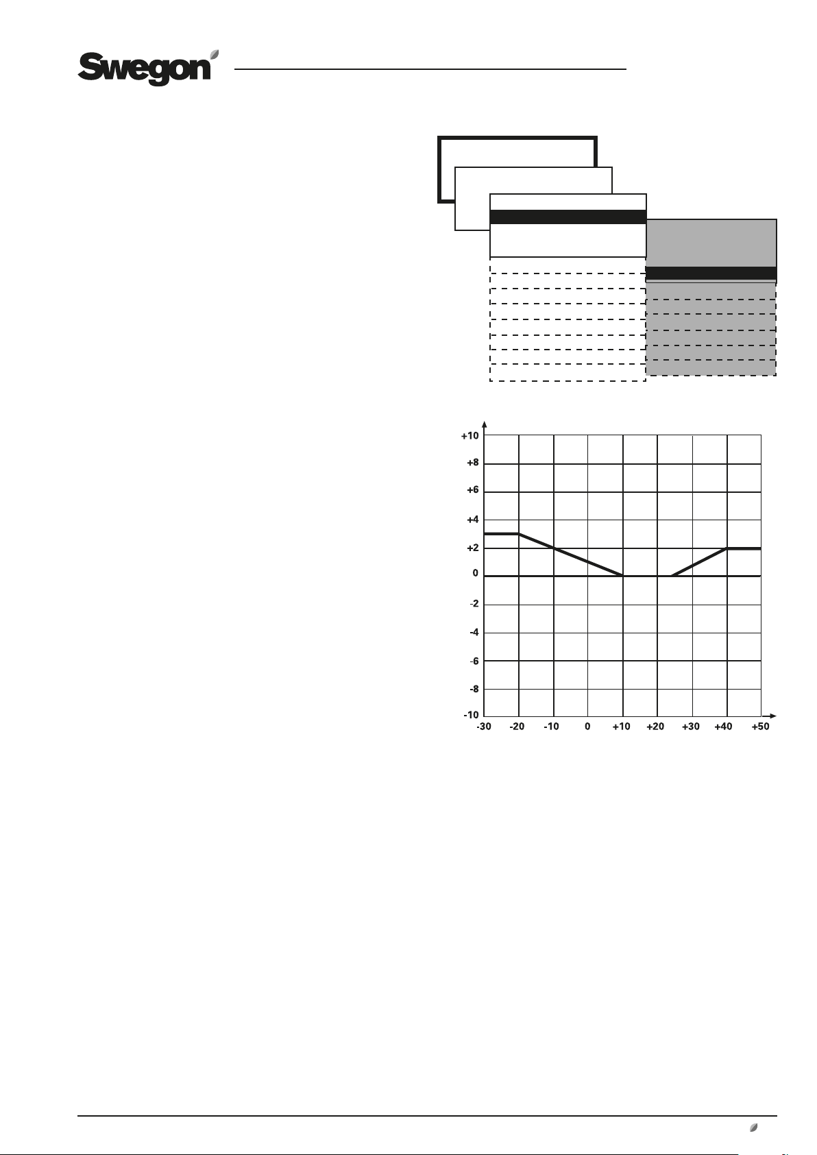
8.2.2 Outdoor Temperature Compensation
Temperature
Outdoor temperature compensation can be activated if
the premises are abnormally subjected to the effects of
seasonal cold air or hot air due to leakage through large
windows, for instance.
The supply air temperature setpoint is compensated if the
air handling unit is operating in the supply air regulation
mode, and the extract air temperature setpoint is compensated if the air handling unit is operating in the extract air
regulation mode. This function will have no effect if the
unit is operating in the ERS regulation mode.
The preset temperature setpoint is influenced if the outdoor temperature drops below the preset X2 breakpoint
(winter compensation) and above the preset X3 breakpoint (summer compensation).
The settings are also applicable to one extra temperature
zone (Xzone), if required.
See the chart to the right.
It is possible to set negative summer compensation.
Settings:
Value Setting Factory
range setting
Winter compensation
Temperature displacement Y1 +0 – +10 °C +3 °C
Breakpoint X1 -30 – -10 °C -20 °C
Breakpoint X2 -10 – +15 °C +10 °C
Summer compensation
Breakpoint X3 +15 – +25 °C +25 °C
Breakpoint X4 +25 – +40 °C +40 °C
Temperature displacement Y2 -10 – +10 °C +2 °C
INSTALLATION
FUNCTIONS
*FUNCTIONS*
TEMPERATURE
AIR FLOW/PRESSURE
FILTER
OPERATION
HEATING
COOLING
HUMIDITY
ReCO
2
IQnomic Plus
ALL YEAR COMFORT
CONTROL Optimize
* TEMPERATURE *
TEMPERATURE REG
TEMP.REG. Xzone
OUTDOOR TEMP COMP
SUMMER NIGHT COOL
INTERM. NIGHT HEAT
MORNING BOOST
SETPOINT TEMP DISPL
EXTRA REG. SEQUENCE
EXT. SENSORS
Outdoor temperature compensation
Y1
X1
X2 X3
Y = Temperature displacement °C
X4
Y2
We reserve the right to alter specifications without notice.
X = Outdoor temperature °C
Winter compensation in accordance with factory setting
involves:
Outdoor temperature +10 °C (Breakpoint X2): Compensation starts and gradually takes place between 0–3 °C
down to outdoor temperature -20 °C.
Outdoor temperature -20 °C (Breakpoint X1): Constant
compensation takes place with 3 °C (temperature displacement Y1).
Summer compensation in accordance with factory setting
involves:
Outdoor temperature +25 °C (Breakpoint X3): Compensation starts and gradually takes place between 0–2 °C up to
outdoor temperature +40 °C.
Outdoor temperature +40 °C (Breakpoint X4): Constant
compensation takes place with 2 °C (temperature displacement Y2).
www.swegon.com 23
GB.GOLDSK509.091101
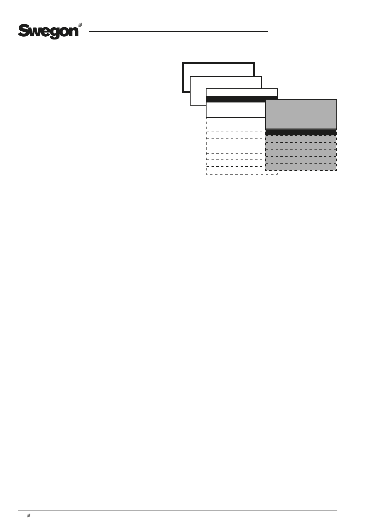
8.2.3 Summer Night Cooling
The lower temperature at night is utilized to cool down
the building structure. This reduces the cooling load
during the first hours of the day. If a cooling unit is
installed, its in-operation hours will be minimized, thus
offering savings. If no cooling unit is installed, a certain
cooling effect will still be realized.
When summer night cooling function is activated, the unit
fans operate at high speed, with a supply air setpoint of
10°C, from the preset time until the conditions necessary
for stop are satisfied.
The extra temperature zone (Xzone), if any, will obtain
the same supply air set point if summer night cooling is in
operation.
Conditions to be met to start summer night cooling at the
preset time:
• The extract air temperature should be higher than the
preset value
• The extract air should be at least 2°C warmer than the
outdoor air.
• The outdoor temperature should be above the preset
value.
• Heating has not been required between 12.00–23.00
hours.
• The unit must not operate in the high speed mode or
be stopped from an external source or manually from the
hand-held micro terminal.
Conditions to be met to stop summer night cooling at the
preset time:
• The extract air temperature drops below the preset
value.
• The outdoor temperature drops below the preset value.
• Switch clock or external input calls for high speed.
• The extract air is less than 1 °C warmer than the outdoor
air.
INSTALLATION
FUNCTIONS
*FUNCTIONS*
TEMPERATURE
AIR FLOW/PRESSURE
FILTER
OPERATION
HEATING
COOLING
HUMIDITY
ReCO
IQnomic Plus
ALL YEAR COMFORT
CONTROL Optimize
* TEMPERATURE *
TEMPERATURE REG
TEMP.REG. Xzone
OUTDOOR TEMP COMP
SUMMER NIGHT COOL
INTERM. NIGHT HEAT
2
MORNING BOOST
SETPOINT TEMP DISPL
EXTRA REG. SEQUENCE
EXT. SENSORS
The function starts once per set time period.
Settings:
Value Setting Factory
range setting
Extract air temperature for start 17 - 27 °C 22 °C
Extract air temperature for stop 12 - 22 °C 16 °C
Outdoor temperature for stop 5 - 15 °C 10 °C
Supply air setpoint 10 - 20 °C 10 °C
Operating period 00:00-00:00 23:00-06:00
24
www.swegon.com
We reserve the right to alter specifications without notice.

GB.GOLDSK509.091101
8.2.4 Intermittent Night-time Heating
The unit is utilized to heat the premises when it is normally
stopped by the switch clock.
The function requires that an external room sensor is connected (control unit terminals 40-41) and that a reheating
coil be installed downstream of the air handling unit. The
function works best if the GOLD is equipped with an air
recirculation section and shut-off dampers for the outdoor
air and the exhaust air.
When the function is activated, the air handling unit
detects when the room temperature drops below the
preset start temperature. The unit starts with preset flows
and the supply air temperature setpoint.
If extract air fan operation is not desirable, the extract
airflow can be set to 0.
The damper output can be set to 0. This means that the
connected dampers (such as shut-off dampers for outdoor
air and extract air) will not be affected. These dampers are
normally closed when the air handling unit is stopped and
they also remain closed. The damper in the air recirculation section is opened at the same time, if one is installed.
Intermittent nighttime heating does not affect a possible
extra temperature zone (Xzone) that regulates according
to its ordinary set point, if intermittent nighttime heating
is in operation.
Conditions to be met for intermittent night-time heating
to start:
• The unit should operate in a time channel/switch clock
stop.
• The room temperature should be below set start temperature.
Conditions to be met for intermittent night-time heating
to stop:
• High speed or external/manual stop should be activated.
• Room temperature should be above the preset stop
temperature.
• Alarm with preset stop priority has tripped.
If the needed, the air handling unit fans will continue to
operate to cool the electric air heater although other conditions for stop have been met.)
Settings:
Value Setting Factory
range setting
Room temperature for start 5 - 25 °C 16 °C
Room temperature for stop 5 - 25 °C 18 °C
Supply air temperature setpoint 10 - 40 °C 28 °C
Supply airflow *) m3/s/Pa **) m3/s/Pa
Extract airflow *) m3/s/Pa 0 m3/s/Pa
Damper output 0=not activated 0
1= activated
Control output*** 0=IQnomic 0
1 =IQnomic Plus
INSTALLATION
FUNCTIONS
*FUNCTIONS*
TEMPERATURE
AIR FLOW/PRESSURE
FILTER
OPERATION
HEATING
COOLING
HUMIDITY
ReCO
2
IQnomic Plus
ALL YEAR COMFORT
CONTROL Optimize
* TEMPERATURE *
TEMPERATURE REG
TEMP.REG. Xzone
OUTDOOR TEMP COMP
SUMMER NIGHT COOL
INTERM. NIGHT HEAT
MORNING BOOST
SETPOINT TEMP DISPL
EXTRA REG. SEQUENCE
EXT. SENSORS
EXTRACT AIR
SUPPLY AIR
Intermittent night-time heating with air recirculation section:
If the extract airflow is set to 0 and the damper output is
not activated, the following takes place:
When conditions for start are met, outdoor air and
exhaust air shut-off dampers remain closed. The damper
in the air recirculation section is opened. The extract air
fan is idle.
The supply air fan operates according to the preset supply
airflow and the heating coil downstream of the air handling unit operates according to the supply air temperature setpoint, until the conditions for stop are met.
*) The setting range is the same as the min/max settings of the
air handling unit.
**) According to the setting for low speed at USER LEVEL under
FLOW/PRESSURE.
*** If IQnomic Plus is selected, extra control sequence and intermittent nighttime heating can be used at the same time.
We reserve the right to alter specifications without notice.
www.swegon.com 25

GB.GOLDSK509.091101
1050
+5
+4
+3
+2
+1
0
-1
-2
-3
-4
-5
8.2.5 Morning BOOST
The unit is utilised to heat the premises during a preset
period prior to the switch-in time set on the switch clock.
The function is used if the air recirculation section is
installed.
The unit starts early and uses the same operation and
temperature regulation settings as it would at the regular
start time.
If the extract air fan is not required to operate, the extract
airflow can be set to 0.
Damper output can be set to be inactive. This means that
connected dampers (e.g. outdoor air and exhaust air shutoff dampers) are not affected. Normally these dampers
are closed when the unit is stopped and thus they remain
closed. At the same time damper in the air recirculation
section opens, if one is installed.
Settings:
Value Setting Factory
range setting
Time for start prior to regular
start time according to switch clock hour, min.
00:00
Damper output Inactive Inactive
Extract air fan Inactive Inactive
Control output*** 0=IQnomic 0
1=IQnomic Plus
Max. flow, supply air * **
Max. flow, extract air * **
*) The adjusting range is the same as the unit’s min./max. setting.
**) According to the setting for max. speed at the USER LEVEL
under FLOW/PRESSURE.
*** If IQnomic Plus is selected, extra control sequence and
Morning BOOST can be used at the same time.
INSTALLATION
FUNCTIONS
*FUNCTIONS*
TEMPERATURE
AIR FLOW/PRESSURE
FILTER
OPERATION
HEATING
COOLING
HUMIDITY
ReCO
IQnomic Plus
ALL YEAR COMFORT
CONTROL Optimize
INSTALLATION
FUNCTIONS
*FUNCTIONS*
TEMPERATURE
AIR FLOW/PRESSURE
FILTER
OPERATION
HEATING
COOLING
HUMIDITY
ReCO
IQnomic Plus
ALL YEAR COMFORT
CONTROL Optimize
* TEMPERATURE *
TEMPERATURE REG
TEMP.REG. Xzone
OUTDOOR TEMP COMP
SUMMER NIGHT COOL
INTERM. NIGHT HEAT
2
2
MORNING BOOST
SETPOINT TEMP DISPL
EXTRA REG. SEQUENCE
EXT. SENSORS
* TEMPERATURE *
TEMPERATURE REG
TEMP.REG. Xzone
OUTDOOR TEMP COMP
SUMMER NIGHT COOL
INTERM. NIGHT HEAT
MORNING BOOST
SETPOINT TEMP DISPL
EXTRA REG. SEQUENCE
EXT. SENSORS
8.2.6 Setpoint Temperature Displacement
Used for changing the supply air and extract air temperature setpoints by means of an external 0-10 VDC signal
(control unit terminals 34-35). The temperature can be
increased or decreased at certain times of the day by
means of an external switch clock or potentiometer, for
instance.
The setpoint can be influenced ±5 °C.
If the unit is operating in the supply air regulation mode,
the supply air temperature is displaced and if the unit is
operating in the extract air regulation mode, the extract
air temperature is displaced.
When the unit is operating in the ERS regulation 1 mode,
the difference between extract air and supply air is influenced. The difference cannot be less than 0 °C. The difference will decrease as the input signal increases.
If the unit is operating in the ERS regulation 2 mode, the
supply air setpoint will be offset.
When the function is activated, the setpoint is offset as
illustrated in the chart to the right.
Set point displacement does not affect a possible extra
temperature zone (Xzone) that regulates according to its
ordinary set point, if set point displacement is in operation.
26
www.swegon.com
Setpoint temp displacement °C
Control signal V DC
Setpoint temp displacement involves:
Control signal 0 V DC: The setpoint is lowered by 5 °C.
Control signal 5 V DC: Unchanged setpoint.
Control signal 10 V DC: The setpoint is increased by 5 °C.
Settings:
Value Setting Factory
range setting
Setpoint temp displacement Inactive/active Inactive
We reserve the right to alter specifications without notice.

GB.GOLDSK509.091101
8.2.7 Extra Regulation Sequence
Used for extra control functions controlled by a 0-10V
signal with ordinary temperature regulation sequence.
The function can be used for utilizing existing heating or
cooling sources, such as from a refrigerating plant. The
function can also be used for an extra cooling or heat coil.
The out signal for the extra regulation sequence is transmitted via the same terminals on the control unit as for an air
recirculation damper, if fitted (terminals 44-45).
The maximal output signal can be limited from 100 %
down to 0 %.
It is possible to combine extra control sequence with intermittent nighttime heating or Morning BOOST (requires the
IQnomic Plus accessory).
Extra regulation sequence can be selected to work in four
different positions as follows:
Cooling operation
• Comfort: 0-10 V output signal sequence after the cooling
function is controlled to 100 %.
• Economy: 0-10 V output signal sequence before the regular cooling function.
Heating operation
• Comfort: 0-10 V output signal sequence after the reheating function is controlled to 100 %.
• Economy: 0-10 V output signal sequence before the regular reheating function.
Settings:
Value Setting range Factory setting
Max output signal
Cooling function
Heating function Inactive
0-100%
Inactive
Comfort
Economy
Comfort
Economy
100%
Inactive
Inactive
INSTALLATION
FUNCTIONS
*FUNCTIONS*
TEMPERATURE
AIR FLOW/PRESSURE
FILTER
OPERATION
HEATING
COOLING
HUMIDITY
ReCO
IQnomic Plus
ALL YEAR COMFORT
CONTROL Optimize
* TEMPERATURE *
TEMPERATURE REG
TEMP.REG. Xzone
OUTDOOR TEMP COMP
SUMMER NIGHT COOL
INTERM. NIGHT HEAT
2
MORNING BOOST
SETPOINT TEMP DISPL
EXTRA REG. SEQUENCE
EXT. SENSORS
8.2.8 External Temperature Sensors
There are two inputs on the IQnomic for external sensors,
which can be used when the internal sensor of the unit
does not provide representative values.
External Extract air/Room (control unit terminals 40-41)
measures the extract air temperature in a larger room or in
the duct system, instead of the temperature inside the air
handling unit.
External Outdoor (control unit terminals 38-39) measures
the outdoor air temperature outdoors, instead of the temperature inside the air handling unit.
As an alternative, a temperature reading can be communicated to the air handling unit from a supervisory system, for
instance.
Settings:
Value Setting range Factory setting
External Extract air/Room Inactive//IQnomic
Communication
External Outdoor Inactive//IQnomic
Communication
Alarms 0 - 9990 min. 5 min.
We reserve the right to alter specifications without notice.
Inactive
Inactive
INSTALLATION
FUNCTIONS
*FUNCTIONS*
TEMPERATURE
AIR FLOW/PRESSURE
FILTER
OPERATION
HEATING
COOLING
HUMIDITY
ReCO
IQnomic Plus
ALL YEAR COMFORT
CONTROL Optimize
* TEMPERATURE *
TEMPERATURE REG
TEMP.REG. Xzone
OUTDOOR TEMP COMP
SUMMER NIGHT COOL
INTERM. NIGHT HEAT
2
MORNING BOOST
SETPOINT TEMP DISPL
EXTRA REG. SEQUENCE
EXT. SENSORS
www.swegon.com 27

GB.GOLDSK509.091101
8.3 Flow/Pressure
Basic functions are set at INSTALLATION LEVEL and
the values are read and set at USER LEVEL.
8.3.1 Fan Regulation
The type of regulation used for the supply air fan and the
extract air fan respectively can be selected individually.
8.3.1.1 Flow Regulation
Flow regulation involves operating the air handling unit
to keep the preset airflow constant. The speed of the fans
is automatically regulated to provide correct airflow even
if the filters begin to become clogged, air devices are
blocked, etc.
Constant airflow is advantageous, since the airflow always
is exactly as it was from the beginning.
It should however be noted that everything that increases
the pressure drop in the ventilation system, such as the
blocking of air devices and dust accumulating in the filters, causes the fans to run at a higher speed. This causes
higher power consumption and may also cause discomfort
in the form of noise.
8.3.1.2 Pressure Regulation
The airflow automatically varies to provide constant pressure in the ducting. This type of regulation is also called
VAV regulation (Variable Air Volume).
Pressure regulation is used when damper operations
increase the air volume in parts of the ventilation system.
The duct pressure is measured by an external in-duct pressure transducer which is wired to the BUS communication
of the control unit. The setpoint setting required (separate
for low speed and high speed) is entered in Pa.
The function can be limited so that the fan speed will not
exceed the preset max. permissible values.
INSTALLATION
FUNCTIONS
*FUNCTIONS*
TEMPERATURE
AIR FLOW/PRESSURE
FILTER
OPERATION
HEATING
COOLING
HUMIDITY
ReCO
2
IQnomic Plus
ALL YEAR COMFORT
CONTROL Optimize
* AIRFLOW/PRESSURE *
SA FAN REGULATION
EA FAN REGULATION
OUTDOOR TEMP COMP.
BOOSTING
SA DOWN REGULATION
SLAVE CONTROL
* AIRFLOW/PRESSURE *
SA FAN REGULATION
EA FAN REGULATION
OUTDOOR TEMP COMP.
BOOSTING
SA DOWN REGULATION
SLAVE CONTROL
Settings:
Value Detting
Fan regulation (SA/EA) Flow regulation
Pressure regulation
Demand control
Slave control
8.3.1.3 Demand Control
The airflow required is regulated in response to 0-10 V
input signals from an external sensor, such as a carbon
dioxide sensor, connected to control unit terminals 30-33.
Required setpoint (separate for low speed and high speed)
is set as a percentage of the input signal.
The function can be limited so that the flow will not be
higher or lower than the preset max. and min. permissible
values respectively.
8.3.1.4 Slave Control
The flow is constantly regulated to be the same from the
one fan as from the other fan. If one fan is pressure-controlled or demand-controlled, the other one can be controlled as a slave to generate the same airflow.
The performance of the fan controlled as a slave can be
restricted if its maximum flow is set to a lower airflow rate.
Both fans cannot be controlled as slaves. If both are
selected by mistake, the extract air fan will be forced to
operate in the flow regulation mode.
28
www.swegon.com
We reserve the right to alter specifications without notice.

GB.GOLDSK509.091101
0%
-50%
-40%
-30%
-20%
-30 -20 -10 0 +10 +20
-10%
8.3.2 Outdoor Temperature Compensation
Airflow
Outdoor temperature compensation of the airflow can be
activated if it is desired to reduce the airflow in the wintertime.
In the flow regulation mode, the current airflow is
reduced. In the pressure regulation mode, the current
setpoint for pressure is reduced.
The function has no effect if the airflow is demand-controlled.
The airflow is reduced as a percentage of the current
airflow/pressure.
Settings:
Value Setting Factory
range setting
Y1, max permissible reduction 0-50% 30 %
X1, breakpoint -30 – -10 °C -20 °C
X2, breakpoint -10 – +15 °C +10 °C
INSTALLATION
FUNCTIONS
*FUNCTIONS*
TEMPERATURE
AIR FLOW/PRESSURE
FILTER
OPERATION
HEATING
COOLING
HUMIDITY
ReCO
IQnomic Plus
ALL YEAR COMFORT
CONTROL Optimize
Y1
* AIRFLOW/PRESSURE *
SA FAN REGULATION
EA FAN REGULATION
OUTDOOR TEMP COMP.
BOOSTING
2
X1
SA DOWN REGULATION
SLAVE CONTROL
X2
8.3.3 Boosting
The airflow is regulated between two flows in response
to a 0-10 V DC input signal from an external source, such
as a potentiometer (connected to control unit terminals
30-33).
Boosting can be used, for example, in assembly halls,
where a higher rate of air change is needed under fullload conditions.
The function is activated only when the unit fans operate
at high speed.
On a 0-10 V DC signal, the fans are gradually accelerated
from the unit’s initial high speed setting to its initial max
speed setting. On a max input 10 V DC signal, the unit
fans operate at max speed.
The function must be activated separately for the supply
air fan and for the extract fan.
Settings:
Value Setting Factory
range settings
Supply air fan Inactive/active Inactive
Extract air fan Inactive/active Inactive
Y = Airflow reduction %
X = Outdoor air temperature °C
Outdoor air compensation according to factory settings
involves:
Outdoor temperature +10 °C (Breakpoint X2): Compensation starts and gradually proceeds between 0–30 %
down to outdoor air temperature -20 °C.
Outdoor air temperature -20 °C (Breakpoint X1): Constant compensation proceeds at 30 % (max reduction
Y1).
INSTALLATION
FUNCTIONS
*FUNCTIONS*
TEMPERATURE
AIR FLOW/PRESSURE
FILTER
OPERATION
HEATING
COOLING
HUMIDITY
ReCO
2
IQnomic Plus
ALL YEAR COMFORT
CONTROL Optimize
* AIRFLOW/PRESSURE *
SA FAN REGULATION
EA FAN REGULATION
OUTDOOR TEMP COMP.
BOOSTING
SA DOWN REGULATION
SLAVE CONTROL
We reserve the right to alter specifications without notice.
www.swegon.com 29

GB.GOLDSK509.091101
8.3.4 Downspeed Control of Fan Speed to Min. Set
Point, Airflow/pressure
Regulation of the supply airflow to a lower flow rate is the
last step in the regulation sequence on increasing heating load for ERS regulation or supply air regulation. The
extract air fan cannot be selected alone; only the supply
air fan or both the supply air and extract air fans can be
selected.
See Section 8.2 as well.
An adjustable temperature decrease allows a lower supply
air temperature setpoint, before down regulation begins.
This neutral zone can be set on line NZ SA DOWN REGU-
LATION in the appropriate menu.
Settings:
Value Setting Factory
range settings
Function Inactive/SA/SA+EA Active
Neutral zone 0.0-10.0 °C 0.0 °C
8.3.5 To adjust the flow of the slave fan
It is possible to preset the set point of the slave fan to
provide a higher or lower airflow than the current airflow
of the controlling fan.
The deviation from the airflow of the controlling fan can
be preset by entering a COP. A cooling COP of 0.5 denotes
that the airflow of the slave will be 50% of the master
fan’s airflow.
Settings:
Value Setting Factory
range settings
Cooling COP 0.5-2,0 1,0
INSTALLATION
FUNCTIONS
*FUNCTIONS*
TEMPERATURE
AIR FLOW/PRESSURE
FILTER
OPERATION
HEATING
COOLING
HUMIDITY
ReCO
IQnomic Plus
ALL YEAR COMFORT
CONTROL Optimize
INSTALLATION
FUNCTIONS
*FUNCTIONS*
TEMPERATURE
AIR FLOW/PRESSURE
FILTER
OPERATION
HEATING
COOLING
HUMIDITY
ReCO
IQnomic Plus
ALL YEAR COMFORT
CONTROL Optimize
* AIRFLOW/PRESSURE *
SA FAN REGULATION
EA FAN REGULATION
OUTDOOR TEMP COMP.
BOOSTING
2
2
SA DOWN REGULATION
SLAVE CONTROL
* AIRFLOW/PRESSURE *
SA FAN REGULATION
EA FAN REGULATION
OUTDOOR TEMP COMP.
BOOSTING
SA DOWN REGULATION
SLAVE CONTROL
8.4 To Activate the GOLD SD Filter Monitoring Function
The filter monitoring function must be activated for the
filters that are to be monitored.
Settings:
Value Setting Factory
range settings
Standard filter Inactive/SA/EA Inactive
SA+EA
Prefilter Inactive/SA/EA Inactive
SA+EA
30
www.swegon.com
INSTALLATION
FUNCTIONS
*FUNCTIONS*
TEMPERATURE
AIR FLOW/PRESSURE
FILTER
OPERATION
HEATING
COOLING
HUMIDITY
ReCO
IQnomic Plus
ALL YEAR COMFORT
CONTROL Optimize
We reserve the right to alter specifications without notice.
2

GB.GOLDSK509.091101
8.5 Operation
8.5.1 Switch clock
Basic functions are set at INSTALLATION LEVEL and
the values are read and set at USER LEVEL.
The switch clock controls the operating times of the unit.
The following two basic functions can be set:
LOW SPEED – HIGH SPEED
Low speed is the basic level and times for high speed operation are set at USER LEVEL under SWITCH CLOCK.
STOP – LOW SPEED – HIGH SPEED
Stop is basic level and times for low speed and high speed
operation are set at USER LEVEL under SWITCH CLOCK.
Settings:
Value Setting range Factory settings
Function Low speed/High speed Low speed/High speed
Stop/Low speed/High speed
INSTALLATION
FUNCTIONS
*FUNCTIONS*
TEMPERATURE
AIR FLOW/PRESSURE
FILTER
OPERATION
HEATING
COOLING
HUMIDITY
ReCO
IQnomic Plus
ALL YEAR COMFORT
CONTROL Optimize
*OPERATION FUNCTION*
SWITCH CLOCK
EXTENDED OPERATION
SUMMER/WINTER TIME
2
8.5.2 Extended Operation
The inputs for external low speed (control unit terminals
46-47) and external high speed (control unit terminals
48-49) respectively, can be supplemented with extended
operation. They can be used for overtime running activated by a pushbutton, for example.
Desired time in hours and minutes can be set as follows.
Settings:
Value Setting Factory
range settings
External low speed 0:00 - 23:59 0:00
External high speed 0:00 - 23:59 0:00
(hour:min) (hour:min)
8.5.3 Summer time/Winter time
The time and date readings include factory-preset automatic changeover from summer time to normal time
and vice versa, thus conforming to EU standard (the last
Sunday in March and the last Sunday in October respectively).
This automatic changeover can be blocked and set as inactive.
Settings:
Value Setting Factory
range settings
Summer time/Winter time Inactive/active Active
*OPERATION FUNCTION*
SWITCH CLOCK
EXTENDED OPERATION
SUMMER/WINTER TIME
*OPERATION FUNCTION*
SWITCH CLOCK
EXTENDED OPERATION
SUMMER/WINTER TIME
We reserve the right to alter specifications without notice.
www.swegon.com 31

GB.GOLDSK509.091101
8.6 Heating
8.6.1 Heat exchanger
8.6.1.1 Defrosting the rotary heat exchanger
In environments where the extract air can occasionally be humid, the defrosting function can be activated to protect the heat exchanger from frosting.
The function continuously monitors the condition
of the heat exchanger rotor to prevent condensate
from freezing in the rotor passages and clogging
them.
The function requires a separate pressure transducer
(preset for heat exchanger defrosting) wired to the control
unit inputs for external BUS communication and connected by hoses to the pressure measuring tappings of the
unit.
See special installation instruction for the TBLZ-1-23-aa
Pressure sensor.
The pressure drop across the rotor must then be calibrated
to establish a reference pressure drop for monitoring purposes. See 6.4.3 Calibration - Heat exchanger.
When the function is activated the pressure drop across
the heat exchanger is continuously measured and the
reading is compared with the calibration reading.
If the pressure drop exceeds the preset limit value, a
defrosting sequence is carried out. This involves, decreasing the rotor speed to approx. 0.5 rpm to allow warm
extract air to melt possible frost.
The defrosting sequence will be cancelled when the pressure drop has fallen to half the limit value. The defrosting
operates for a max permissible period of 30 minutes.
If the pressure drop has not decreased within that max
permissible period after six tries during a 24-hour period,
an alarm will be initiated.
Note that the heat exchanger performs less efficiently
while defrosting is in progress and that the supply air temperature will decrease downstream of the heat exchanger.
Settings:
Value Setting Factory
range settings
Defrosting Inactive/active Inactive
8.6.1.2 Exhaust air regulation, rotary heat
exchanger
The exhaust air regulation function can be used
whenever the exhaust air temperature is not permitted to be below a predetermined value.
The function controls the heat exchanger rotor speed
(efficiency) in order to limit the exhaust air temperature
to the required value. The function decelerates the heat
exchanger rotor speed from the current level, until the
exhaust air temperature drops to the preset min. permissible setting.
INSTALLATION
FUNCTIONS
*FUNCTIONS*
TEMPERATURE
AIR FLOW/PRESSURE
FILTER
OPERATION
HEATING
COOLING
HUMIDITY
ReCO
2
IQnomic Plus
ALL YEAR COMFORT
CONTROL Optimize
Defrosting function with separate pressure transducers, in principle
*HEAT*
HEAT EXCHANGE
REHEAT
HEATING BOOST
EXTRACT AIR
Exhaust air regulation requires a separate temperature
sensor (TBLZ-1-58-aa; accessory) fitted in the air handling
unit exhaust air path.
See special installation instructions for the internal TBLZ-158-aa temperature sensor.
Settings:
Value Setting Factory
range settings
Exhaust air regulation Inactive/Activated Inactive
Min. exhaust air -10 – + 20.0 °C 5.0 °C
temperature
32
www.swegon.com
We reserve the right to alter specifications without notice.

GB.GOLDSK509.091101
8.5.2 Reheating
AIR HEATER FOR HOT WATER
If the “pump or pump + valve” exercising mode is
selected, the relay output is activated (control unit terminals 5 and 6) whenever heating is required and this starts
the circulation pump of the air heater.
If the outdoor temperature is low (colder than +12 °C),
the pump output contact is continuously activated. During
other times, the pump output contact is activated 2
min/24 hours for exercising of circulation pump.
ELECTRIC AIR HEATER
If “pump exercising mode inactive” has been selected, the
relay output is activated (control unit terminals 5 and 6)
whenever heating is required.
The relay output can be used for indicating or blocking the
external function.
EXERCISING MODE
Settings:
Value Setting Factory
range settings
Function Inactive/pump/ Pump
pump+valve/
valve
Exercise period 1 – 60 min. 3 min.
Interval 1 – 168 hrs. 24 hrs.
INSTALLATION
FUNCTIONS
*FUNCTIONS*
TEMPERATURE
AIR FLOW/PRESSURE
FILTER
OPERATION
HEATING
COOLING
HUMIDITY
ReCO
IQnomic Plus
ALL YEAR COMFORT
CONTROL Optimize
*HEAT*
HEAT EXCHANGE
2
REHEAT
HEATING BOOST
8.5.3 Heating BOOST
Heating boost means that the air handling unit, operating in the normal flow regulation mode, increases both
the supply airflow and the extract airflow in order to carry
more heat into the premises.
The fans are allowed to work in the range between current flows (low speed, high speed) and preset max speed
flow.
The function only works if the air handling unit is operating in the extract air regulation mode. If demand control
or boost is selected in combination with heating boost,
the flow is controlled by the function that transmits the
highest output signal to the fans.
This function cannot be combined with pressure regulation.
The flow increase starts steplessly when there is a difference of 2-10°C (3°C is factory preset) to preset max supply
air temperature. When max supply air temperature has
been reached, the unit runs at preset max flow (For particulars of how to set the max flow, see Section 6.3.2).
Settings:
Value Setting Factory
range settings
Heating BOOST Inactive/active Inactive
Start limit 2-10 °C 3 °C
INSTALLATION
FUNCTIONS
*FUNCTIONS*
TEMPERATURE
AIR FLOW/PRESSURE
FILTER
OPERATION
HEATING
COOLING
HUMIDITY
ReCO
IQnomic Plus
ALL YEAR COMFORT
CONTROL Optimize
*HEAT*
HEAT EXCHANGE
2
REHEAT
HEATING BOOST
We reserve the right to alter specifications without notice.
www.swegon.com 33

GB.GOLDSK509.091101
8.7 Cooling
8.7.1 Operation
Activate the cooling function.
8.7.2 Cooling Regulation
CoolDX -Economy (without heat exchanger)
Used when the CoolDX cooling unit is connected via bus
cable.
Both cooling relays of the air handling unit operate in parallel
with each relay on the IQnomic plus module in the CoolDX
cooling unit.
CoolDX - Comfort
Used when the CoolDX cooling unit is connected via bus
cable. The heat exchanger in the GOLD unit operates in
sequence with the cooling unit to even out the supply air temperature. Important! Requires an extra outdoor temperature
sensor.
Use the TBLZ-1-30 accessory for mounting an outdoor air
temperature sensor in the ductwork upstream of the CoolDX.
Use the TBLZ-1-2 4/5 accessory for installing the outdoor air
temperature sensor outdoors.
COOL DXS
For use when the COOL DXS cooling unit is connected via
a bus cable. The COOL DXS operates downstream of the
heat exchanger in the GOLD air handling unit.
Stepless 0-10 V DC
Used when variable cooling control is connected. The air handling unit cooling controller modulates a 0-10 V DC signal that
is linear with the cooling load (control unit terminals 42-43).
Both the cooling relays of the unit operate in parallel with the
signal and are energized when the cooling signal exceeds 0.5
V DC and are de-energized when the signal drops below 0.2
V DC.
The output for cooling relay 1 is connected to terminals 7-8
and for cooling relay 2 to terminals 9-10.
Stepless 10-0 V DC
Same as above, but the control signal is inverted where a 10 V
output signal means a 0 % cooling load.
On/off, 1 Step
Used if cooling in one step is connected. The air handling
unit’s cooling controller regulates the cooling load at 0-100
%. Cooling relays 1 and 2 are energized when the cooling
load exceeds 5 % and are de-energized when the cooling load
is less than 2 %.
The output contact for 0-10 V DC control signals (terminals
42-43) operates in parallel with the 0-100 % cooling demand
and can be used for indicating the cooling demand, for
instance.
INSTALLATION
FUNCTIONS
*FUNCTIONS*
TEMPERATURE
AIR FLOW/PRESSURE
FILTER
OPERATION
HEATING
COOLING
HUMIDITY
ReCO
2
IQnomic Plus
ALL YEAR COMFORT
CONTROL Optimize
* COOLING *
OPERATION MODE
COOL REGULATION
PERIODIC OPERATION
REGULATION SPEED
OUTDOOR TEMP LIMIT
RESTART TIME
COOL MIN AIR FLOW
NEUTRAL ZONE
COOLING BOOST
On/off, 2 steps
Used when cooling in 2 steps is connected. The air handling
unit’s cooling controller regulates the cooling load at 0-100 %.
Cooling relay 1 is energized when the cooling load exceeds 5
% and is de-energized when the cooling load is less than 2 %.
Cooling relay 2 is energized when the cooling load exceeds 55
% and is de-energized when the cooling load is less than 50
%.
The 0-10 V DC control signal output (terminals 42-43) operates in parallel with the 0-100 % cooling demand and can be
used for indicating the cooling demand, for instance.
On/off, 3 Steps - Binary
Used when cooling with two inputs controlled with three
binary steps is connected. The cooling controller of the unit
regulates the cooling demand at 0-100 %.
On an increasing cooling load:
Cooling relay 1 is energized when the cooling load is
above 5 % and is de-energised when the cooling load is
between 40-70 %. Cooling relay 2 is energized when the
cooling load is above 40 %. Cooling relay 1 is energized
again (together with cooling relay 2) when the cooling
load is above 70%.
On a decreasing cooling load:
Cooling relay 1 drops when cooling load is below 60 %, it is
energized again when cooling load is below 30 % and drops
again when cooling load is below 2 %. Cooling relay 2 drops
when cooling load is below 30 %.
The output for 0-10 V DC control signals (terminals 42-43)
operates in parallel with the 0-100 % cooling load and can be
used for indicating the cooling demand, for instance.
34
www.swegon.com
We reserve the right to alter specifications without notice.

Settings for cooling functions on this page and the next:
Value Setting Factory
range settings
Operation mode Inactive/active Inactive
Cooling regulation CoolDX
Stepless 0-10 V Stepless 0-10 V
Stepless10-0 V
On/Off 1 step
On/Off 2 step
On/Off 3 step binary
COOL DXS
Periodic operation
Cooling relay 1 Inactive/pump/ Inactive
pump+valve/valve
Cooling relay 2 Inactive/pump/ Inactive
pump+valve/ valve
Exercise period 1 – 60 min.
3 min.
Interval 1 – 168 hrs. 24 hrs.
Regulation speed
between steps 0-600 sec 300 sec
Outdoor temperature limit
Step 1 0-25 °C 3 °C
Step 2 0-25 °C 5 °C
Step 3 0-25 °C 7 °C
Restart time 0-900 sec 480 sec
Cooling min air flow
Supply air 0-Max flow –
Extract air 0-Max flow –
Neutral zone 0-10 °C 2.0 °C
Cooling BOOST Inactive Inactive
Comfort
Economy
Sequence
Comfort+economy
Economy+ sequence
Start limit in
connection to
min supply air temp 2-10 °C 3 °C
GB.GOLDSK509.091101
We reserve the right to alter specifications without notice.
www.swegon.com 35

GB.GOLDSK509.091101
See preceding page for possibilities of setting.
8.7.3 Periodic Operation
Can be selected to run pumps if cooling relay 1 and/or 2
are used.
The exercising mode can be selected for “pump, pump +
valve” or “valve” only (0 - 10 V output). The pumps are
exercised 2 minutes per day if this is activated.
8.7.4 Regulation Speed
The required delay period between the various cooling
steps can be set.
This is done so that a compressor, for instance, will have
time generate required cooling capacity before the next
cooling step is switched in.
This applies to changeover from step 1 to step 2 and from
step 2 to step 3; and only on an increasing cooling load.
8.7.5 Outdoor Temperature Limit
Provision is available for setting an outdoor temperature-related blocking function in 3 steps. If the outdoor
temperature is below each step limit, the function of the
cooling relays will be blocked.
This function also restricts the 0-10 V output signal to
transmission in steps.
Step 1 maximises the output signal to 2.5 V, step 2 to 5.0
V and step 3 to 7.5 V.
8.7.6 Restart Time
The time should be set in such a way that it follows the
recommendations of the cooling machine supplier for the
number of starts per hour.
The restart time is calculated from the time when a relay is
energized to when it is allowed to be energized again.
The 0-10 V signal is delayed during the same period.
8.7.7 Cooling Min Air Flow
In order for the cooling function to operate the supply air
and extract air airflows must be greater than their respective limit values (preset at USER LEVEL under FLOW/PRESSURE).
The cooling min flow function can be blocked by setting
both flow limits to 0.
8.7.9 Cooling BOOST
Cooling BOOST means that the supply air and extract air
airflows are increased to convey more cooling energy to
the premises.
Cooling BOOST cannot be combined with pressure regulation.
The flow increase takes place between current flow and
preset max flow.
The function can be selected in three variants as follows:
Comfort
The cooling outputs are activated if there is a cooling load.
When the cooling function is active and the temperature
in the supply air drops toward the preset SA min temperature, the flow will steplessly increase.
The GOLD runs at preset max flow when the supply air
temperature is same as the min. temperature.
Economy
Cooling BOOST Economy first uses a higher airflow to cool
the premises, before a start signal is transmitted to the
cooling machines.
The function can also operate without the cooling function being activated.
On a cooling load, the flows are slowly increased up to
preset maximum flow. When the flows are up to max and
if a cooing load is still present, the output contacts for
cooling are activated.
The cooling boost function requires an outdoor air temperature of at least 2 °C lower than the extract air temperature for it to be activated. Normal cooling operation is
activated if the temperature difference is too small.
Sequence
The cooling BOOST Sequence is used if a cooling machine
is sized for a higher than normal cooling flow.
If there is a cooling load, the flow is increased up to the
preset max flow before the cooling function is activated.
The cooling function is delayed 1 minute after the airflow
is increased.
The cooling boost sequence is blocked if no cooling function has been selected.
8.7.8 Neutral Zone
The neutral zone prevents the cooling and heating systems
from counteracting each other.
Preset neutral zone is added to the setpoint for heating
and the sum of these provides the setpoint for cooling.
36
www.swegon.com
We reserve the right to alter specifications without notice.

GB.GOLDSK509.091101
8.8 Humidity
Dehumidification control
The dehumidification function controls the moisture in the
supply air duct by switching in and switching out a cooling coil
and a postheating coil.
The function requires that a cooling coil be mounted upstream of
a postheating coil in the supply air duct, see the example to the
right.
The TBLZ-1-31-1 moisture sensor is mounted in the supply air
duct and its cable is connected to the appropriate terminal on
the GOLD unit.
Cooling energy is emitted to condense the moisture in the supply
air flow, which then is heated to the desired supply air temperature. This causes a reduction in the moisture content of the
supply air.
The cooling unit used must be sized so that the temperature of
the supply air will be below the dew point, otherwise no condensation will arise and no dehumidification will occur.
Settings:
Value Setting Factory
range settings
Dehumidification Inactive/active Inactive
Supply air – rel. humidity (%RH) 10-90% 50%
INSTALLATION
FUNCTIONS
*FUNCTIONS*
TEMPERATURE
AIR FLOW/PRESSURE
FILTER
OPERATION
HEATING
COOLING
HUMIDITY
ReCO
2
IQnomic Plus
ALL YEAR COMFORT
CONTROL Optimize
*HUMIDITY*
DEHUMIDIF. CTRL.
Example of dehumidification control
Temperature sensor,
supply air
Moisture sensor, TBLZ-1-31-1
We reserve the right to alter specifications without notice.
www.swegon.com 37

GB.GOLDSK509.091101
8.9 ReCO2
The ReCO2 function is used for controlling the TBBR air
recirculation section in sequence with CO2 control or temperature control, for instance.
If both the CO2 and the temperature functions are
selected, the function with the presently lowest signal
(highest outdoor air set point) will apply.
CO
function:
2
The air recirculation rate increases if the input signal for
CO2 (0-10 V DC) is low and decreases if the input signal is
high.
CO
+ flow function:
2
The air recirculation rate increases if the input signal for
CO2 (010 V DC) is low and decreases if the input signal is
high. If the input signal for CO2 still is too high without air
recirculation, the airflow will be steplessly increased to the
max. preset flow setting.
Temperature function for heating, economy:
Recirculation takes place upstream of the reheater.
Temperature function for heating, comfort:
Recirculation takes place downstream of the reheater.
Temperature function for cooling, economy:
Recirculation takes place upstream of air cooler.
Temperature function for cooling, comfort:
Recirculation takes place downstream of the air cooler.
Settings:
Value Setting Factory
range settings
CO2 function Inactive/CO2 / CO2 +flow
Inactive
Temp. function – heating Inactive/ Inactive
economy/
comfort
Temp. function – cooling Inactive/ Inactive
economy/
comfort
Min. outdoor air * m3/s * m3/s
Min. exhaust air * m3/s * m3/s
INSTALLATION
FUNCTIONS
*FUNCTIONS*
TEMPERATURE
AIR FLOW/PRESSURE
FILTER
OPERATION
HEATING
COOLING
HUMIDITY
ReCO
2
IQnomic Plus
ALL YEAR COMFORT
CONTROL Optimize
Outdoor air
Outdoor air
The outdoor airflow is kept constant in response to pressure
sensor readings. See special installation instruction for the TBLZ1-23-aa Pressure sensor.
When the recirculation damper opens, the speed of the extract
air fan is reduced and vice versa.
*ReCO2*
FUNCTION OFF/ON
SETTINGS
Extract air
Supply air
Pressure sensor for outdoor air
measurements.
* The setting range is equivalent to the min./max. setting range
of the air handling unit.
8.10 IQnomic Plus
IQnomic Plus is a name given to additional modules for
extra control functions.
See the special instructions for the IQnomic Plus, and
wherever applicable the relevant Function Guide.
38
www.swegon.com
INSTALLATION
FUNCTIONS
*FUNCTIONS*
TEMPERATURE
AIR FLOW/PRESSURE
FILTER
OPERATION
HEATING
COOLING
HUMIDITY
ReCO
IQnomic Plus
ALL YEAR COMFORT
CONTROL Optimize
We reserve the right to alter specifications without notice.
2
*IQnomic Plus*

GB.GOLDSK509.091101
8.11 All Year Comfort
The All Year Comfort function controls the supply flow
temperature to comfort modules, chilled beams, perimeter
climate systems, etc. via regulating valves. Two strap-on
temperature sensors fitted either to the water pipe or the
regulating valve are used for measuring the water temperature.
The function requires the electrical equipment cubicle
accessory (TBLZ-1-59-a-b-cc) for controlling the supply
flow water temperature. The function selector switch of
the electrical equipment cubicle must be set to position 7.
All Year Comfort has functions for outdoor compensation,
room compensation, night compensation, dew point compensation and for controlling pump and valve exercising.
For further information, see the Guide to the All Year
Comfort Function.
Settings:
Value Setting Factory
range settings
All Year Comfort Inactive Inactive
Cooling
Heating
Cool.+Heat.
Heating water temperature (°C) 10-80°C 30
Cooling water temperature (°C) 5-30°C 14
Outdoor comp. Heat. water Active Inactive
Inactive
Outdoor temp. (X1) (°C) -40 - 40°C -20
Heating water (Y1)(°C) 10 - 80°C 40
Outdoor temp. (X2)(°C) -40 - 40°C 5
Heating water (Y2)(°C) 10 - 80°C 30
Outdoor temp. (X3)(°C) -40 - 40°C 15
Heating water (Y3)(°C) 10 - 80°C 20
Outdoor comp., Cool. water Active Inactive
Inactive
Outdoor temp. (X1) (°C) -40 - 40°C 10
Cooling water (Y1)(°C) 5 - 30°C 22
Outdoor temp. (X2)(°C) -40 - 40°C 20
Cooling water (Y2)(°C) 5 - 30°C 18
Outdoor temp. (X3)(°C) -40 - 40°C 25
Cooling water (Y3)(°C) 5 - 30°C 14
Room comp., Heating water Active Inactive
Inactive
Room temperature (°C) 0 - 40°C 21
P-band (°C) 1 - 10°C 5
Night blocking Active Active
Inactive
Room comp., Cooling water Active Inactive
Inactive
Room temperature (°C) 0 - 40°C 21
P-band(°C) 1 - 10°C 5
Night blocking Active Active
Inactive
Night comp., heating water Active Inactive
Inactive
Temp. comp. (°C) -10 - +10°C -2
Night comp., Cooling water Active Inactive
Inactive
Temp. comp. (°C) -10-+10 °C 2
INSTALLATION
FUNCTIONS
*FUNCTIONS*
TEMPERATURE
AIR FLOW/PRESSURE
FILTER
OPERATION
HEATING
COOLING
HUMIDITY
ReCO
2
IQnomic Plus
ALL YEAR COMFORT
CONTROL Optimize
Night comp. Inactive Inactive
Monday
Tuesday
Wednesday
Thursday
Friday
Saturday
Sunday
Monday-Friday
Monday-Sunday
Saturday-Sunday
Channel 1-2
Pump op., Heating water
Outdoor temp. Start (°C) -40 - 40°C 15
Pump op., Heating water
Outdoor temp. Stop (°C) -40 - 40°C 18
Pump op., Cooling water
Outdoor temp. Start (°C) -40 - 40°C -20
Pump op., Cooling water
Outdoor temp. Stop (°C) -40 - 40°C -25
Pump/valve
Pump alarm, heating water Inactive Inactive
Normally closed
Normally open
Contactor
Valve, heating water Active Inactive
Inactive
Pump alarm, cooling water Inactive Inactive
Normally closed
Normally open
Contactor
Valve, cooling water Active Inactive
Inactive
Exercising, heating water Inactive Inactive
Pump
Pump+Valve
Valve
Exercising period, (min) 1-60 min 3
Interval (h) 1-168 h 24
Exercising, Cooling water Inactive Inactive
Pump
Pump+Valve
Valve
Exercising period, (min) 1-60 min 3
Interval (h) 1-168 h 24
Dew point comp. Active Inactive
Inactive
Neutral zone(°C) 0-5°C 2
Comp. flow (%) 0-30% 10
*ALL YEAR COMFORT*
FUNCTION ON/OFF
SETTINGS
We reserve the right to alter specifications without notice.
www.swegon.com 39

GB.GOLDSK509.091101
8.12 CONTROL Optimize
The CONTROL Optimize function optimizes the GOLD
unit’s airflow rates for the connected WISE system. See the
special documentation for WISE.
INSTALLATION
FUNCTIONS
*FUNCTIONS*
TEMPERATURE
AIR FLOW/PRESSURE
FILTER
OPERATION
HEATING
COOLING
HUMIDITY
ReCO
IQnomic Plus
ALL YEAR COMFORT
CONTROL Optimize
2
40
www.swegon.com
We reserve the right to alter specifications without notice.

GB.GOLDSK509.091101
9 AUTOMATIC FUNCTIONS
9.1 General
The GOLD has a number of automatic functions. The operation
of the unit is influenced when certain functions are activated.
9.1.1 Starting Sequence
The GOLD has a starting sequence with factory-preset time delay
between every step as follows:
1. The damper relay is energized and opens the shut-off damper
(if installed).
Time delay: 30 seconds.
2. The extract air fan starts (not applicable if only GOLD SD
supply air handling units are installed) and the heat exchanger
is controlled to provide max. heat recovery (Not applicable to
GOLD SD units without heat exchanger). Additional heating (if
installed) is activated to generate 40% of its max capacity.
Time delay: 90 seconds.
3. The supply air fan starts (not applicable if only GOLD SD
extract air handling units are installed)
Time delay: 180 seconds (from the time when the extract air fan
has started).
4. The temperature regulation function begins according to its
regular settings.
The starting sequence prevents the extract air fan from starting if
the shut-off damper is closed. By starting the extract air fan first,
and the heat exchanger as well, the system also avoids chilling
the premises with cool supply air under cold weather conditions.
9.1.2 Cooling Recovery
Cooling energy recovery is an automatic function that helps the
air handling unit utilize the relative “cooling energy” that may be
present indoors if cooling is required and the outdoor temperature is high.
The heat exchanger rotates at max. speed and in this way recovers the relative cooling energy or chilliness in the extract air.
The conditions for this function to be activated are that there is a
cooling demand and that the outdoor temperature is 1 °C higher
than the extract air. The function is switched out when the cooling load ceases to exist or when the outdoor temperature is the
same as that of the extract air.
The text COOLING RECOVERY is shown in the hand-held micro
terminal.
9.1.3 Zero Point Calibration
The pressure transducer of the unit is automatically calibrated.
This calibration is carried out 3 minutes after the unit has been
stopped.
The text ZERO PT CALIBR is shown in the hand-held micro terminal.
The fans cannot start while calibration is in progres
9.1.4 Anti-frost Monitoring Function – Air Heater for
Hot Water
The anti frost monitoring function is always active if the air
heater for hot water connected has been supplied by Swegon.
The function activates a heating device that maintains 13 °C in
the coil while the air handling unit is in operation and 25 °C in
the coil when the unit is stopped. An alarm is initiated and the
unit is stopped if the temperature sensor senses a temperature
below 7 °C.
s.
9.1.5 Additional cooling – Electric Air Heater
The fans continue to operate at min speed for 3 minutes after
the air handling unit has been stopped to cool the electric heating elements if the electric air heater has been operating.
The text ADD COOLING appears in the hand-held micro terminal.
9.1.6 Reduction in output, electric air heater
A min. permissible air velocity of 1.5 m/s is required for preventing the electric heating elements from becoming overheated
when they are generating full heating output.
If the air handling unit supply airflow drops below the value
that corresponds to an air velocity of 1.5 m/s across the heat
exchanger the heating output of the air heater will be automatically reduced.
The text REDUCTION IN OUTPUT appears in the hand-held micro
terminal.
9.1.7 Additional running - Heat Exchanger
The rotary heat exchanger automatically continues to rotate ca 1
minute after the air handling unit has been stopped.
It takes a little time for the fans to stop rotating after a stop order
has been entered in the micro terminal. This prevents the admis-
sion of cool supply air into the premises.
9.1.8 Density-corrected Airflow
The density of the air is different at different temperatures. This
means that a specific volume of air will change at different air
densities.
The GOLD automatically corrects this, so that correct air volume
is always obtained.
The control equipment always shows the corrected airflow.
9.1.9 Purging Operation
Purging is an automatic function that prevents the rotary
heat exchanger from standing still in the same position
for a longer period when no heating is necessary.
Purging operation is activated when the unit is operating but the
heat exchanger rotor is not rotating. The heat exchanger rotor
then rotates for 10 seconds every 10 minutes to purge its sur-
faces clean of impurities.
9.1.10 Carry-over Control
Whenever the fans generate low airflows, the speed
of the rotary heat exchanger is reduced to an appropriate level for correct purging airflow through the heat
exchanger.
9.1.11 Calculaton of the efficiency of the rotary
heat exchanger
The efficiency is calculated and displayed (0 – 100%).
9.1.12 Pump control for the coil heat exchanger
The pump of the pipework package starts when
heat recovery is needed.
If heat recovery is not needed for more than 24
hours, the pump is exercised once a day.
We reserve the right to alter specifications without notice.
www.swegon.com 41

9.1.13 Anti-frosting protection for the
plate/coil heat exchanger
In cold weather, and if the extract air is humid, there is risk
of frosting in plate/coil heat exchangers. The GOLD PX/CX
is equipped with anti-frosting protection.
GOLD PX (plate heat exchanger)
The temperature inside the heat exchanger’s ”cold
corner” and the humidity in the extract air are measured.
Taking the humidity into consideration, the control system
calculates the lowest permissible temperature without risk
of frosting inside the heat exchanger. The by-pass damper
is then controlled to prevent the temperature from dropping below this limit.
GB.GOLDSK509.091101
GOLD CX (coil heat exchanger) and
GOLD SD with coil heat exchanger
The temperature of the liquid circulated to the extract air
coil and the humidity in the extract air are measured.
Taking the humidity into consideration, the control system
calculates the lowest permissible temperature without risk
of frosting inside the coil.
The valve in the pipework package is then controlled to
prevent the temperature from dropping below this limit.
10 READINGS
The operating status and the values can be read. Used for
performance checks and for generally checking values,
settings, power consumption, etc.
No values can be altered in this menu group.
Each menu indicates which values can be read.
The operation times per 24 hour period are given under
the OPERATION TIME menu.
11 MANUAL TEST
Note! Manual test running can cause indoor comfort problems. There is also risk of overloading the
system. The responsibility for discomfort and overload rests totally on the person who activates the
function.
Manual test run can take place for testing the inputs and
outputs, fans and heat exchanger, etc.
Used when the air handling unit is first installed to make
sure that all the connections have been correctly wired.
Most alarms, functions and normal control modes will be
blocked while manual testing is in progress.
On a return to the other menu groups, the controller
resumes normal operation and all settings for manual testing will be terminated.
Each menu indicates which functions can be test run.
INSTALLATION
READINGS
INSTALLATION
MANUAL TEST
*READINGS*
TEMPERATURE
FANS
HEAT EXCHANGE
REGULATION SIGNALS
IN/OUTPUTS
HUMIDITY
ReCO
2
IQnomic Plus
ALL YEAR COMFORT
OPERATION TIME
PROGRAM VERSIONS
*MANUAL TEST*
TEMPERATURE
FANS
HEAT EXCHANGE
REHEAT
EXTRA REG. SEQ.
COOLING
IN/OUTPUTS
ReCO
2
IQnomic Plus
ALL YEAR COMFORT
42
www.swegon.com
We reserve the right to alter specifications without notice.

GB.GOLDSK509.091101
12 ALARM SETTINGS
12.1 Fire Alarms
EXTERNAL FIRE ALARM
Inputs 54 and 55 are used for external fire protection equipment.
The resetting of alarms can be selected to occur manually or automatically.
INTERNAL FIRE ALARM
The air handling unit’s internal temperature sensors serve as fire
protection thermostats. An alarm is initiated if the supply air temperature sensor registers more than 70 °C or when the extract air
temperature sensor registers more than 50 °C.
If an external Extract air/Room temperature sensor is connected and
activated, this works parallel with the extract air temperature sensor
of the unit.
FANS IN THE EVENT OF A FIRE
The fans in the air handling unit can be used for evacuating gases,
etc.
The activated function works together with the External fire/smoke
function or Internal fire alarm.
If the air handling unit is idle, the pre-selected fans will start up
regardless of whether External Stop or Manual Stop has been activated in the hand-held micro terminal.
The damper relay in the air handling unit is energized and the
operating relay drops.
The dampers pre-selected for service in the event of a fire, should
be wired to the damper relay (control unit terminals 22-24) and
these dampers will open.
The dampers that are meant to close in the event of a fire, should
be wired to the in-operation relay (control unit terminals 19-21) and
these dampers will close.
FAN SPEED IN THE EVENT OF FIRE
Will be activated automatically if the fans have been activated in
event of fire (see above), and make it possible to restrict the max
speed of the fans.
Settings:
Value Setting range Factory setting
Internal fire alarm 0=inactive
1=activated
External fire alarm auto/manual manual
Fan in event of fire Inactive/EA/SA/
SA+EA
Fan speed in event of
fire, SA
Fan speed in event of
fire, EA
12.2 External Alarms
EXTERNAL ALARMS 1 and 2
The external alarms can be used for external functions (control unit
terminals 50-51 and 52-53).
Typical uses:
– Motor protection for the circulation pump in the heating or cool-
ing circuit.
– Service alarm actuated by smoke detectors.
Set the time delay and set whether the alarm shall be activated on
closure or disconnection of the input.
10-100% 100%
10-100% 100%
0
Inactive
INSTALLATION
ALARM SET
*ALARM SETTINGS*
FIRE ALARM
EXTERNAL ALARMS
ALARM LIMITS
ALARM PRIORITY
Settings:
Value Setting Factory
range settings
Time delay 1-600 sec 10 sec
Alarm at closure 1=closure 1
0=disconnection
Alarm reset
12.3 Alarm Limits
Changes in the factory-preset alarm limits should only be
made if you have special reasons for doing so and you
should be aware of the consequences.
TEMPERATURE
DEVIATION SA-TEMP (deviating supply air temperature) indicates
how much the supply air temperature is allowed to be below the
supply air temperature setpoint before an alarm is initiated.
MIN EA-TEMP (min extract air temperature) indicates how low the
extract air temperature is allowed to be before alarm is initiated.
FILTERS
SUPPLY AIR/EXTRACT AIR indicates at which level of contamination
in the supply air filter that an alarm will trip.
HEAT EXCHANGER
ALARM LIMIT indicates at which pressure rise an alarm will trip,
if there is an extra installed pressure transducer for the defrosting
function of the heat exchanger.
SERVICE PERIOD
SERVICE PERIOD indicates the period until the next service.
Settings:
Value Setting Factory
range settings
TEMPERATURE
Deviating supply air temp. 2-15 °C 5 °C
Min extract air temp. 8-20 °C 15 °C
FILTERS
Supply air 50-300 Pa 100 Pa
Extract air 50-300 Pa 100 Pa
Supply air, prefilter. 50-300 Pa 100 Pa
Extract air, prefilter. 50-300 Pa 100 Pa
HEAT EXCHANGER
Alarm limit 30-100 Pa 50 Pa
SERVICE PERIOD
Alarm limit 0-99 months 12 months
ALARM OUTPUTS
0=auto/1=man 0
We reserve the right to alter specifications without notice.
www.swegon.com 43

12.4 Alarm Priority
There should be special reasons for alteration of alarm priority and you should be aware of the consequences.
Changes in priority should only be made if you have special
reasons for doing so and you should be aware of the consequences. The priority of certain alarms cannot be changed.
Settings:
See 17.2 Alarm Descriptions.
12.5 Alarm outputs
Alarm outputs A and B can be selected with normally
open or normally closed function.
Settings:
Value Setting Factory
range setting
Output A NO/NC Normally open
Output B NO/NC Normally open
GB.GOLDSK509.091101
44
www.swegon.com
We reserve the right to alter specifications without notice.

GB.GOLDSK509.091101
13 HAND-HELD TERMINAL
13.1 Language
The language desired can be set here. Normally this setting is entered when the air handling unit is started for the
first time and the question ÄNDRA/CHANGE? automatically appears in the hand-held terminal.
However, the language setting can be changed at any
time.
Settings:
Value Setting Factory
range settings
Language Current languages English
is listed in the menu.
13.2 Air flow unit
The air flow unit desired can be set here.
Settings:
Value Setting Factory
range settings
Flow unit l/s m3/s
m3/s
m3/h
13.3 Min/Max Adjustment
Used for restricting the setting range at user level for setpoints as well as for min. and max. temperature limits.
Settings:
Value Setting Factory
range settings
For EA and SA regulation
Setpoint, min 10-30°C 15°C
Setpoint, max 10-40°C 40°C
For EA regulation
Min SA, min 8-20°C 13°C
Max SA, min 8-20°C 18°C
Min SA, max 16-50°C 25°C
Max SA, max 16-50°C 45°C
For ERS regulation 1
Breakpoint, min 12-26°C 15°C
Breakpoint, max 12-26°C 23°C
EA/SA Diff, min 1-7°C 1°C
EA/SA Diff, max 1-7°C 5°C
EA = Extract air
SA = Supply air
ERS= Extract air temperature-related supply air temperatureregulation
INSTALLATION
HAND TERMINAL
*HANDTERMINAL SET*
LANGUAGE
AIR FLOW UNIT
MIN/MAX SETTING
BASE SETTINGS
13.4 Base Settings
Used for saving and resetting the settings.
BASE SETTINGS 1 and 2 are two levels where the user
him-/herself saves current settings and activates them
when needed.
The two base settings can be used as a summer setting
and as a winter setting of the air handling unit.
The values in INITIAL SETTING 1 and 2 saved in the internal
memory can be transferred to the external MMC memory
by entering SAVE SETTINGS. EXTERNAL MEMORY.
The values can be transferred from the external MMC
memory to the internal memory by entering FETCH
EXTERNAL MEMORY.
INITIAL SETTING 1 and 2 must be downloaded into the
control unit by entering INTERNAL MEMORY, LOAD NEW
SETTINGS.
Under SAVE EXTERNAL MEMORY, there is a function that
can save current settings to the MMC memory.
Current settings can be stored directly in the control unit
under FETCH EXTERNAL MEMORY
FACTORY SETTINGS resets the air handling unit’s settings
to the original values it had when it was supplied (See
19.2 Commissioning Record).
The preset values for communication and alarm priority
are not reset if the factory settings are reinstated.
Settings:
Value Setting range
Save/fetch setting
Save setting – internal memory Save new setting 1
Save new setting 2
external memory Save setting 1
Save setting 2
Save current setting
Save all
Load/fetch – internal memory Load new setting 1
Load new setting 2
external memory Fetch setting 1
Fetch setting 2
Fetch current setting
Fetch all
Factory setting Activate
We reserve the right to alter specifications without notice.
www.swegon.com 45

GB.GOLDSK509.091101
14 COMMUNICATION
Provision for communication and supervision is integrated as standard into the GOLD. The unit is ready
to be connected via EIA-232, EIA-485 and Ethernet.
For particulars of connecting and wiring the air
handling unit, see Section 19.5 Wiring to Terminals,
Sizes 04-80.
Communication can also be established via Ethernet without software other than an ordinary web
browser such as Internet Explorer.
Further information about interfaces, protocol and configuration is available at www.
swegon.com.
14.1 EIA-232
Protocol and settings for EIA-232 is specified.
Settings:
Value Setting range
Modbus RTU Address, speed, parity, stop bits
GSM-modem
Analogue modem
14.2 EIA-485
Protocol and settings for EIA-485 is specified.
Settings:
Value Setting range
Modbus RTU Address, speed, parity, stop bits
Metasys N2 OPEN
Lon Works/TREND
Exolinc
INSTALLATION
COMMUNICATION
*COMMUNICATION*
EIA-232
EIA-485
ETHERNET
14.3 Ethernet
Protocol and settings for Ethernet is specified.
Settings:
Value Setting range
Ethernet MAC ID
DHCP SERVER
(active or inactive)
IP ADDRESS
(static or dynamic)
SUBNETM.
GATEWAY
DNS-SERVER
MODBUS TCP CLIENT
(IP address and mesh)
BACNet IP
(active or inactive, Device ID,
Port no.)
15 SERVICE LEVEL
A code and special training are required for access to this
menu group.
INSTALLATION
SERVICE LEV.
*SERVICE LEV.*
CODE:0000
46
www.swegon.com
We reserve the right to alter specifications without notice.

GB.GOLDSK509.091101
A
A
16 MAINTENANCE
Warning
Before carrying out any work, make sure that the
power supply to the unit has been isolated.
16.1 Filter Change
The filters should be changed when the filter alarm has been
activated.
Order new filters from Swegon or its representative!
State the size of the GOLD unit and whether the change involves
one or two air directions.
16.1.1 To remove the Filters
Pull out the handles (A) to free the filters from the filter holder.
Withdraw the filters.
It is advisable to clean inside the filter space while the filters are
gone.
16.1.2 To fit new filters
Insert the filters into the filter holder. At the same time, stretch
out the filter bags, so that they will not get caught, hurt or
become folded.
Insert the filters as far as possible into the unit and press lightly
on the filter frames, so that they will fit tightly.
Push in the handles (A) so that the filters are clamped in place in
the filter holder.
Carry out a filter calibration as described in Section 6.4.2.
16.2 Cleaning and Inspection
16.2.1 General
Clean the interior of the air handling unit as the need arises.
Inspect the air handling unit thoroughly at the same time that
you replace the filters or at least twice a year.
16.2.2 Filter Space
Cleaning is most appropriate when you change the filters.
16.2.3 Heat exchangers
Check at least twice a year whether cleaning is necessary.
The cleaning work is carried out from the filter space.
Rotary heat exchanger
The heat exchanger should preferably be cleaned by vacuum
cleaning with a soft nozzle to prevent damaging the air passages
in the rotor.
Turn the rotor by hand to enable you to vacuum clean its entire
surface.
If the heat exchanger is substantially fouled, it can be blown
clean with compressed air.
If necessary, the heat exchanger can be withdrawn from the unit
casing and washed with degreasing solvent. Only service personnel trained by Swegon shall be permitted to use this cleaning
method.
FABRIC SEAL
Lift up the fabric seal and inspect its underside. Clean if needed
by brushing or vacuum cleaning.
If the fabric seal is worn or substantially fouled, it should be
replaced. Do not lubricate it!
BELT TENSION
Replace the drive belt if it feels loose or worn and slightly slips
if it meets resistance. Contact service personnel trained by
Swegon!
Plate heat exchanger
Always clean against the regular direction of airflow.
Cleaning shall only be done by blowing with compressed air,
vacuum cleaning with a soft nozzle or wet cleaning with water
and/or solvent. Before you begin cleaning, cover adjacent functional sections to protect them.
If cleaning solvent is used, do not use solvent that will corrode
aluminium or copper. Swegon’s cleaning agent is recommended.
This cleaning agent is sold by Swegon Service.
Inspect the condensate drain to make sure that it isn’t clogged.
The by-pass and shut-off dampers do not require maintenance.
Coil heat exchanger
Make sure that the coils are purged of air. If a droplet eliminator
is fitted, remove it and flush it clean with water.
Always clean against the regular direction of airflow.
Cleaning shall only be done by blowing with compressed air,
vacuum cleaning with a soft nozzle or wet cleaning with water
and/or solvent. Before you begin cleaning, cover adjacent functional sections to protect them.
If cleaning solvent is used, do not use solvent that will corrode
aluminium or copper. Swegon’s cleaning agent is recommended.
This cleaning agent is sold by Swegon Service.
While cleaning, check the content of glycol in the water and the
condition of the coil for tightness. Also check that the condensate drain is not clogged.
16.2.4 Fans and Fan Space
Inspect and clean the fan impellers to remove possible dirt
deposits.
Check the impeller to make sure that it is not out of balance.
Clean or brush off the fan motor. It can also be cleaned by
carefully wiping it with a damp cloth that has been dipped in a
solution of water and dishwashing detergent.
Clean the fan space, if needed.
16.3 Performance Checks
General performance checks should be carried out in conjunction with filter change or at least once a year.
It is then appropriate to compare the current performance values
of the unit with the Commissioning Record. Eventual deviations
should be remedied.
We reserve the right to alter specifications without notice.
www.swegon.com 47

GB.GOLDSK509.091101
16.4 To change the pump, pipework package, GOLD CX, sizes 35-80
Before the pump can be replaced, the coils will have to be partially emptied.
An electrician or a duly qualified person skilled in electrical installations is required to disconnect and connect the power supply
cable to the pump.
To empty the coils:
It isn’t necessary to completely empty the system; it will be sufficient to empty to a level just below the pump.
For the variants in which the pump is arranged above the expansion vessel, the system can be emptied from the header by the
expansion vessel.
For the other variants, the venting or drain nipples on the lower
coils should be used for emptying.
Open the venting valve on the upper coil as well.
To remove the old pump:
Remove the insulation material around the pump and make note
of the direction of liquid flow.
Disconnect the electrical connections from the pump.
Remove the bolts on the pump’s flange connections and remove
the pump.
Remove the old gaskets and clean the surfaces where they have
been seated.
To mount the new pump:
Fit the new gaskets.
Check the direction of flow of the new pump and mount it so
that the direction of liquid flow will be the same as before.
Tighten the bolts on the pump’s flange connections.
Wire the electrical connections to the pump.
To refill the coils:
When refilling, fill with glycol of the type used in brine systems;
not the type used in motor vehicles!
always 30% from the factory.
The total volume of glycol/water is 122 litres in size 35/40,
176 litres in size 50/60 and 231 litres in size 70/80 units.
Open the valve on the header by the expansion vessel and connect the filling hose.
Start the external filling pump and refill the coils. The filling
pump should hold a pressure of approx 1 bar .
Use the venting valves to vent both the upper and lower coils.
Close the lower venting valve when liquid, free of air bubbles,
flows out.
Close the upper venting valve when liquid, free of air bubbles,
flows out.
Start the internal circulation pump and make sure that the direc-
tion of rotation is correct.
The green LED on the terminal box of the pump shall be lit while
the pump is operating. If the red LED is lit, the pump impeller is
rotating in the wrong direction.
Operate the unit for approx. 10 minutes, then vent both the upper and lower coils.
Close the filling valve and switch off the pump.
Remove the hoses and re-insulate the pump.
Operate the unit for approx. 1 week, then vent both the upper
and lower coils again.
The glycol content is
17 ALARMS AND FAULT TRACING
17.1 General
Alarms are indicated by an alarm text and flashing LED in
the hand-held micro terminal.
Fire alarms and frost alarms are shown in all the menu
images. Other alarms are only shown if you are in the
Main menu.
Active, but time-delayed alarms can be viewed quickly at
USER LEVEL under ALARMS. The 10 most recently initiated
alarms can also be read in this menu.
A fault can be traced by examining the function or function section indicated in the alarm text.
Faults can also be traced via the READINGS menu or the
MANUAL TEST menu at Installation level.
If the fault cannot immediately be remedied:
Consider whether the air handling unit can continue to
operate until the fault has been remedied. Choose to
block the alarm and/or to change it from STOP to OPERATION (See Section 12, Alarm settings).
17.1.1 A and B-alarms
Type A alarms transmit an alarm signal to the alarm relay A
output (control unit terminals 15-16).
Type B alarms transmit an alarm signal to the alarm relay B
output (control unit terminals 17-18).
From these terminals, alarms can be forwarded with different priority.
The alarm relays can be selected to have normally open or
normally closed function.
17.1.2 Resetting of alarms
Alarms that require manual resetting can be reset from
the hand-held micro terminal. Select RESET in the current
alarm menu.
Alarms that reset themselves automatically do so as soon
as the fault has been remedied.
Alarms can also be reset via a communication network.
17.1.3 Changing Alarm Settings
See Section: 12 Alarm Settings.
17.1.4 Start up after a power failure
Automatic or manual start up after a power failure can be
selected.
48
www.swegon.com
We reserve the right to alter specifications without notice.

17.2 Alarm Descriptions with Factory Settings
GB.GOLDSK509.091101
Alarm text
Function
Alarm no.
EXTERNAL FIRE ALARM TRIPPED
1
For the fire protection function connected to terminals 54-55.
INTERNAL FIRE ALARM TRIPPED
2
The air handling unit’s supply air sensor measures a
temperature more than 70 °C and/or its extract air
sensor measures a temperature more than 50 °C.
The function must be activated manually in the
ALARM SETTINGS menu.
FROST PROTECTION BELOW ALARM LIMIT
3
The anti-frosting monitor sensor measures a temperature lower than the preset temperature. Factory
setting: 7 °C.
R.HX.SPEED MONITOR TRIPPED
4
No impulses from the rotation detector are registered
with the heat exchanger controller. The air handling
unit will be switched out only if the outdoor temperature drops below 5 °C.
FROST PROTECTION SENSOR DEFECTIVE
5
The anti-frosting monitor temperature sensor is lacking, is not connected or is faulty; an air heater for hot
water is connected.
Priority Stop Indication
Delay Resetting
LED
0=blocked 0=In operat. 0=Off s=seconds M=manual
A=A alarm 1=Stop 1=On m=minutes A=automatic
B=B alarm
A**** 1* 1 3 s M
A **** 1* 1 3 s M
A **** 1* 1 3 s M
A 0** 1 3 s M
A **** 1* 1 3 s A
SUPPLY AIR TEMP SENSOR DEFECTIVE
6
EXTRACT AIR TEMP SENSOR DEFECTIVE
7
The supply air/extract air temperature sensor is not
connected or is faulty.
(Not applicable if only GOLD SD supply air or extract
air handling units are installed, see Alarm No. 82)
OUTDOOR AIR TEMP SENSOR DEFECTIVE
8
The outdoor air temperature sensor is not connected
or is faulty. (Not applicable to GOLD SD units, see
Alarm No. 81)
NO COMMUNICATION TO R.HX. CONTROLLER
9
The air handling unit’s control unit cannot establish
correct communication with the heat exchanger
controller.
NO COMMUNICATION TO SA FREQUENCY CONV.
10
NO COMMUNICATION TO EA FREQUENCY CONV.
11
The air handling unit’s control unit cannot establish
correct communication with frequency inverter.
OVER CURRENT IN SA FREQUENCY CONV.
12
OVER CURRENT IN EA FREQUENCY CONV.
13
Current above the normal level is supplied to the
motors.
UNDER VOLTAGE IN SA FREQUENCY CONV.
14
UNDER VOLTAGE IN EA FREQUENCY CONV.
15
Voltage below the normal level is supplied.
OVER VOLTAGE IN SA FREQUENCY CONV.
16
OVER VOLTAGE IN EA FREQUENCY CONV.
17
Voltage above the normal level is supplied.
A
A
1
1
B 0 1 3 s A
A*** 1 1 10 s A
A ***
A ***
A ***
A ***
A ***
A ***
A ***
A ***
1
1
1
1
1
1
1
1
* Not adjustable, always stops the air handling unit.
** Not adjustable, stops the air handling unit if the temperature to below +5 ºC.
*** Blocked if the hand terminal does not display the main menu.
**** Cannot be blocked.
We reserve the right to alter specifications without notice.
1
1
1
1
1
1
1
1
1
1
3 s
3 s
10 s
10 s
3 s
3 s
3 s
3 s
3 s
3 s
www.swegon.com 49
A
A
A
A
M
M
M
M
M
M

GB.GOLDSK509.091101
Alarm text
Function
Alarm no.
OVER TEMPERATURE IN SA FREQUENCY CONV.
18
OVER TEMPERATURE IN EA FREQUENCY CONV.
19
High temperature inside the inverter.
NO COMMUNICATION TO SA-2 FREQUENCY CONV.
20
NO COMMUNICATION TO EA-2 FREQUENCY CONV.
21
The air handling unit’s control unit cannot establish
correct communication
with slave frequency inverter.
Applicable to only sizes 50-80.
OVER CURRENT IN SA-2 FREQUENCY CONV.
22
OVER CURRENT IN EA-2 FREQUENCY CONV.
23
Current above the normal level is supplied to slave
motor.
Applicable to sizes 50-80 only
UNDER VOLTAGE IN SA-2 FREQUENCY CONV.
24
UNDER VOLTAGE IN EA-2 FREQUENCY CONV.
25
Voltage below the normal level is supplied to slave
frequency inverter.
Applicable to sizes 50-80 only.
OVER VOLTAGE IN SA-2 FREQUENCY CONV.
26
OVER VOLTAGE IN EA-2 FREQUENCY CONV.
27
Voltage above the normal level is supplied to slave
frequency inverter.
Applicable to sizes 50-80 only.
OVER TEMPERATURE IN SA-2 FREQUENCY CONV.
28
OVER TEMPERATURE IN EA-2 FREQUENCY CONV.
29
High temperature inside the slave frequency inverter.
Applicable to sizes 50-80 only
EXT.EA/ROOM TEMP SENSOR DEFECTIVE
30
Temperature sensor in extract air duct or room is not
connected (terminals 40-41) or is faulty; or has been
selected with communication.
Applicable if the External sensor, extract air/room or
Intermittent night-time heating function is selected.
EXT.OUTDOOR TEMP SENSOR DEFECTIVE
31
Temperature sensor for outdoor temperature is not
connected (terminals 38-39) or is faulty; or has been
selected with communication.
Applicable if the External outdoor sensor function is
selected.
PLATE HEAT EXCH SENSOR FAULTY
32
The temperature sensor in the exchanger cube for
the anti-frosting monitor is absent or is faulty.
COIL HEAT EXCH SENSOR FAULTY
33
The temperature sensor on the coil heat exchanger’s
pipework package for the anti-frosting monitor is
absent or is faulty.
OVER CURRENT IN R.HX. CONTROLLER
34
Current above the normal level is supplied to the
rotary heat exchanger’s drive motor.
UNDER VOLTAGE IN R.HX. CONTROLLER
35
Feed voltage (25V) is supplied to the rotary heat
exchanger’s drive motor.
OVER VOLTAGE IN R.HX. CONTROLLER
36
Voltage above the normal level (55 V) is supplied to
the rotary heat exchanger’s drive motor.
Priority Stop Indication
Delay Resetting
LED
0=blocked 0=In operat. 0=Off s=seconds M=manual
A=A alarm 1=Stop 1=On m=minutes A=automatic
B=B alarm
A ***
A ***
A ***
A ***
A ***
A ***
A ***
A ***
A ***
A ***
A ***
A ***
1
1
1
1
1
1
1
1
1
1
1
1
1
1
1
1
1
1
1
1
1
1
1
1
3 s
3 s
10 s
10 s
3 s
3 s
3 s
3 s
3 s
3 s
3 s
3 s
M
M
A
A
M
M
M
M
M
M
M
M
A *** 1 1 3 s A
B *** 0 1 3 s A
A *** 0 1 3 s A
A *** 0 1 3 s A
A *** 1 1 3 s M
A *** 1 1 3 s M
A *** 1 1 3 s M
*** Blocked if the hand terminal does not display the main menu.
50
www.swegon.com
We reserve the right to alter specifications without notice.

GB.GOLDSK509.091101
Alarm text
Function
Alarm no.
OVER TEMPERATURE IN R.HX. CONTROLLER
37
High internal temperature (90°C for the rotary heat
exchanger’s controller).
R.HX. PRESSURE DROP ABOVE ALARM LIMIT
38
The heat exchanger’s defrosting function has operated for the full max period 6 times during one
24-hour period.
EL.HEATING COIL TRIPPED
39
The thermal overload protection has tripped or is not
connected.
EXTRACT AIR TEMP BELOW ALARM LIMIT
40
The extract air temperature is below preset alarm
limit for more than 20 minutes.
SUPPLY AIR TEMP BELOW SETPOINT
41
The supply air temperature is below the preset setpoint (for ERS and Supply air regulation) or Min
SA temp (for Extract air regulation) longer than 20
minutes.
EXT. ALARM No.1 TRIPPED
42
External alarm, connected to control unit terminals
50-51, has tripped.
EXT. ALARM No.2 TRIPPED
43
External alarm, connected to control unit terminals
52-53, has tripped..
SA DUCT PRESSURE BELOW SETPOINT
44
EA DUCT PRESSURE BELOW SETPOINT
45
Pressure in supply/extract air duct, if pressure transducers are connected, has been more than 10%
below its setpoint for more than 20 minutes.
SA DUCT PRESSURE ABOVE SETPOINT
46
EA DUCT PRESSURE ABOVE SETPOINT
47
Pressure in supply/extract air duct, if pressure transducers are connected, has been more than 10%
above its setpoint for more than 20 minutes.
SUPPLY AIRFLOW BELOW SETPOINT
48
EXTRACT AIRFLOW BELOW SETPOINT
49
The supply/extract airflow has been more than 10%
below its setpoint for more than 20 minutes.
SUPPLY AIRFLOW ABOVE SETPOINT
50
EXTRACT AIRFLOW ABOVE SETPOINT
51
The supply/extract airflow has been more than 10%
above its setpoint for more than 20 minutes.
SUPPLY AIR FILTER DIRTY
52
EXTRACT AIR FILTER DIRTY
53
The pressure across the supply /extract air filters has
exceeded the preset alarm limit for more than 10
minutes.
Priority Stop Indication
Delay Resetting
LED
0=blocked 0=In operat. 0=Off s=seconds M=manual
A=A alarm 1=Stop 1=On m=minutes A=automatic
B=B alarm
A *** 1 1 3 s M
B *** 0 1 3 s M
A *** 1 1 3 s M
A *** 1 1 20 m M
A *** 1 1 20 m M
A *** 1 1 Set time M
B *** 0 1 Set time M
B ***
B ***
B ***
B ***
B ***
B ***
B ***
B ***
B ***
B ***
0
0
0
0
0
0
0
0
0
0
1
1
1
1
1
1
1
1
1
1
20 m
20 m
20 m
20 m
20 m
20 m
20 m
20 m
10 m
10 m
M
M
M
M
M
M
M
M
M
M
*** Blocked if the hand terminal does not display the main menu.
We reserve the right to alter specifications without notice.
www.swegon.com 51

GB.GOLDSK509.091101
Alarm text
Function
Alarm no.
SERVICE PERIOD PAST ALARM LIMIT
54
The preset service period has expired.
If the alarm is RESET via the hand-held micro terminal, the alarm will be initiated again after 7 days.
A new service period can be set in the ALARM SETTINGS menu.
NO COMM. SA AIR FLOW PRESSURE SENSOR
55
NO COMM. EA AIR FLOW PRESSURE SENSOR
56
The air handling unit’s control unit cannot establish
correct communication with the supply/extract air
flow pressure transducer.
NO COMM. SA FILTER PRESSURE SENSOR
57
NO COMM. EA FILTER PRESSURE SENSOR
58
The air handling unit’s control unit cannot establish
correct communication with the supply/extract air
filter pressure transducer.
NO COMM. SA DUCT PRESSURE SENSOR
59
NO COMM. EA DUCT PRESSURE SENSOR
60
The air handling unit’s control unit cannot establish
correct communication with the pressure transducer
connected in the supply/extract air ducting.
Applicable to SA /EA pressure regulation only.
NO COMM. R.HX. PRESSURE SENSOR
61
The air handling unit’s control unit cannot establish
correct communication with the pressure transducer
connected for the heat exchanger.
Applicable to the defrosting function only.
Priority Stop Indication
Delay Resetting
LED
0=blocked 0=In operat. 0=Off s=seconds M=manual
A=A alarm 1=Stop 1=On m=minutes A=automatic
B=B alarm
B *** 0 1 Set time M
A ***
A ***
B ***
B ***
A ***
A ***
1
1
0
0
1
1
1
1
1
1
1
1
10 s
10 s
10 s
10 s
10 s
10 s
A
A
A
A
A
A
B *** 0 1 10 s A
NO COMMUNICATION TO I/O-MODUL NR 1–9
62-71
The air handling unit’s control unit cannot establish correct communication with the connected I/O
module 1–9
Correct communication can be established between
72
the CPU circuit card and the control unit*s I/O
processor.
PLATE HEAT EXCH, DAMPER MOTOR FAULTY
73
The damper motor does not move to the right position. The position-confirming output signal from the
damper is not equivalent to the input control signal.
COIL HEAT EXCH, PUMP TRIPPED
74
No response is received from the contactor. The motor prot. or the contactor may be faulty.
SUPPLY AIR HUMIDITY SENSOR FAULTY
75
The communication with the humidity sensor in
the supply air duct is faulty or the sensor reading is
erroneous.
EXTRACT AIR HUMIDITY SENSOR FAULTY
76
The communication with the humidity sensor in the
extract air duct is faulty or the sensor reading is erroneous.
B *** 0 1 10 s A
A 1 1 30 s A
A *** 1 1 10 m M
A *** 1 1 20 s M
A *** 1 1 10 s A
A *** 1 1 10 s A
*** Blocked if the hand terminal does not display the main menu.
52
www.swegon.com
We reserve the right to alter specifications without notice.

GB.GOLDSK509.091101
Alarm text
Function
Alarm no.
SPARE
77
HUMIDITY SENSOR, HEAT EXCH FAULTY
78
Communication with the humidity sensor in the
extract air upstream of the heat exchanger is faulty or
the sensor reading is erroneous.
COIL HEAT EXCH, VALVE FAULTY
79
The valve actuator does not move to the right position. The position-confirming output signal from the
actuator is not equivalent to the input control signal.
TEMPERATURE MONITOR - BELOW ALARM LIMIT
80
The temperature reading from the sensor in the inlet
of the supply air fan is below the preset alarm limit.
SUPPLY AIR-D TEMP SENSOR FAULTY (RX/PX/CX)
81
The temperature sensor in the supply air fan inlet has
no comm. or its reading is erroneous.
OUTD. AIR TEMP SENSOR DEFECTIVE (SD)
The sensor for outdoor temperature is not connected
or is faulty.
EXTRACT AIR-D TEMP SENSOR FAULTY
82
Air handling unit with coil or plate heat exch.
The temperature sensor in the extract air fan inlet has
no comm. or its reading is erroneous.
Air handling unit with rotary heat exch.
Exhaust air regulation has been selected, but the
temperature sensor in the exhaust air is not connected or is faulty.
SA SENSOR DEFECTIVE (SD, supply AHU only)
EA SENSOR DEFECTIVE (SD, extract AHU only)
The sensor for supply air/extract air temperature is
not connected or is faulty.
SA PREFILTER FOULED
83
The pressure across the supply air prefilter has constantly exceeded the preset alarm limit for 0 minutes.
EA PREFILTER FOULED
84
The pressure across the extract air prefilter has constantly exceeded the preset alarm limit for 0 minutes.
COOLDX, C1 TRIPPED
85
No contactor replay received at DI1 I/0-module 6 in
cooling unit. The motor protection or the pressure
switch may have tripped.
Priority Stop Indication
Delay Resetting
LED
0=blocked 0=In operat. 0=Off s=seconds M=manual
A=A alarm 1=Stop 1=On m=minutes A=automatic
B=B alarm
B *** 0 1 10 s A
A *** 1 1 10 m M
A *** 1 1 30 s A
B ***
B
B ***
A
A
0
0
0
1
1
1
1
1
!
1
10 s
3 s
10 s
3 s
3 s
A
A
A
A
A
B *** 0 1 10 m M
B *** 0 1 10 m M
A 0 1 20 s M
COOLDX, C2 TRIPPED
86
No response is received from the contactor at DI2
I/0-modul 6 in cooling unit. The motor prot. or the
pressure switch may have tripped.
COOLDX C1 TOO MANY RESTARTS
87
Compressor 1 has started more than 20 times in 2
hours, due to a tripped in-service pressure switch.
COOLDX C2 TOO MANY RESTARTS
88
Compressor 2 has started more than 20 times in 2
hours, due to a tripped in-service pressure switch.
A 0 1 20 s M
A 1 1 3 s M
A 1 1 3 s M
*** Blocked if the hand terminal does not display the main menu.
We reserve the right to alter specifications without notice.
www.swegon.com 53

GB.GOLDSK509.091101
Alarm text
Function
Alarm no.
NO COMM. SA PREFILTER PRESS. SENSOR
89
The air handling unit’s control unit cannot establish
correct communication with supply air prefilter pressure sensor.
NO COMM. EA PREFILTER PRESS. SENSOR
90
The air handling unit’s control unit cannot establish
correct communication with extract air prefilter pressure sensor.
FROST PROTECTION, PREHEATING, BELOW ALARM LIMIT
91
The sensor for the frost protection monitor, preheating, has measured a temperature lower than the
preset temperature. Factory setting: 7 °C.
FROST PROTECTION PREHEATING SENSOR DEFECTIVE
92
The sensor for the frosting protection monitor, preheating, is lacking, is not connected or is faulty, if an
air heater for hot water is connected.
PREHEATING SENSOR DEFECTIVE
93
The sensor for preheating is lacking, is not connected
or is faulty, if an air heater for hot water is connected.
EL. AIR HEATER, PREHEATING, TRIPPED
94
The thermal overload protection for the connected
electric air preheater, has tripped or is not connected.
PREHEATING BELOW SETPOINT
95
The preheating temperature is below the preset setpoint (for ERS and Supply air control) or Min SA temp
(for Extract air control) longer than 0 minutes.
SPARE
96
Priority Stop Indication
Delay Resetting
LED
0=blocked 0=In operat. 0=Off s=seconds M=manual
A=A alarm 1=Stop 1=On m=minutes A=automatic
B=B alarm
B*** 0 1 10 s A
B*** 0 1 10 s A
A 1 1 3 s M
A 1 1 3 s A
A 1 1 3 s A
A*** 1 1 3 s M
A*** 1 1 20 m M
NO COMMUNICATION ReCO PRESSURE SENSOR
97
The air handling unit’s control unit cannot establish
correct communication with the flow pressure sensor
for ReCO.
ReCO DAMPER MOTOR FAULTY
98
The damper motor does not actuate damper to
the right position. The position-confirming output
signal from the damper is not equivalent to the input
control signal.
TIME LOCK TRIPPED
99
Contact Swegon or their representative.
SPARE
100-
A*** 1 1 10 s A
A*** 1 1 10 m M
– – – –**** M
101
COOLING VALVE I/O-7 DEFECTIVE
102
Controls of the Cooling valve do not obtain the same
signal on AI 1 as on AU1 on I/O-module.
HEATING VALVE I/O-7 DEFECTIVE
103
Controls of the Heating valve do not obtain the
same signal on AI 2 as on AU2 on I/O-module
COOL. CIRCUIT PUMP I/O-7 TRIPPED.
104
Controls of the cooling circuit pump do not obtain
correct signal according to set function.
B*** 1 0 10 m M
A*** 1 0 10 m M
B*** 1 0 30 s M
*** Blocked if the hand terminal does not display the main menu.
**** Adjustable: 0-99 months.
54
www.swegon.com
We reserve the right to alter specifications without notice.

GB.GOLDSK509.091101
Alarm text
Function
Alarm no.
HEAT. CIRCUIT PUMP I/O-7 TRIPPED
105
Controls of the heating circuit pump do not obtain
correct signal according to set function.
COOLING WATER TEMP I/O-7 BELOW SET POINT
106
Temperature for cooling water control on I/O module
is continuously 7°C below its current set point.
HEATING WATER TEMP I/O-7 BELOW SET POINT.
107
Temperature for heating water control on I/O module
is continuously 7°C below its current set point.
COOLING WATER TEMP I/O-7 ABOVE SET POINT
108
Temperature for cooling water control on I/O module
is continuously 7°C above its current set point.
HEATING WATER TEMP I/O-7 ABOVE SET POINT
109
Temperature for heating water control on I/O module
is continuously 7°C above its current set point.
COOLING WATER TEMP SENSOR I/O-7 DEFECTIVE
110
Obtained if the cooling water temperature sensor
temp is not connected or is defective.
HEATING WATER TEMP SENSOR I/O-7 DEFECTIVE
111
Obtained if the heating water temperature sensor is
not connected or is defective.
Priority Stop Indication
Delay Resetting
LED
0=blocked 0=In operat. 0=Off s=seconds M=manual
A=A alarm 1=Stop 1=On m=minutes A=automatic
B=B alarm
A*** 1 1 30 s M
B*** 1 1 30 m M
A*** 1 1 30 m M
0*** 1 1 30 m M
0*** 1 1 30 m M
B 1 1 3 s A
A 1 1 3 s A
SPARE
112-
134
SA FAN MOTOR BLOCKED
135
Motor shaft does not rotate during start up.
EA FAN MOTOR BLOCKED
136
Motor shaft does not rotate during start up.
SA-2 FAN MOTOR BLOCKED
137
Motor shaft does not rotate during start up.
EA-2 FAN MOTOR BLOCKED
138
Motor shaft does not rotate during start up.
FLUCTUATION VOLTAGE BETWEEN THE PHASES, SA
139
High voltage difference between the phases
(3-phase, 400 V), which causes rippling.
FLUCTUATION VOLTAGE BETWEEN THE PHASES, EA
140
High voltage difference between the phases
(3-phase, 400 V), which causes rippling.
FLUCTUATION VOLTAGE BETWEEN THE PHASES,
141
SA-2
High voltage difference between the phases
(3-phase, 400 V), which causes rippling.
FLUCTUATION VOLTAGE BETWEEN THE PHASES,
142
EA-2
High voltage difference between the phases
(3-phase, 400 V), which causes rippling.
A*** 1 1 3 sec. M
A*** 1 1 3 sec. M
A*** 1 1 3 sec. M
A*** 1 1 3 sec. M
A*** 1 1 3 sec. M
A*** 1 1 3 sec. M
A*** 1 1 3 sec. M
A*** 1 1 3 sec. M
We reserve the right to alter specifications without notice.
www.swegon.com 55

GB.GOLDSK509.091101
Alarm text
Function
Alarm no.
NO COMMUNICATION W CONTROL OPTIMIZE
143
The AHU control unit cannot establish correct communication with CONTROL Optimize.
NO COMMUNICATIONI/O-MODULE No. A-F
144-
The air handling unit’s control unit cannot estab-
149
lish correct communication with the connected I/O
module A–F
FROST PROTECTION, EXTRA ZONE, BELOW ALARM LIMIT
150
The sensor for the frost protection monitor, extra
zone, has measured a temperature lower than the
preset temperature. Factory setting: 7 °C
FROST PROTECTION, EXTRA ZONE, FAULTY
151
The sensor for the frosting protection monitor, extra
zone, is lacking, is not connected or is faulty, if an air
heater for hot water is connected.
SUPPLY AIR SENSOR, EXTRA-ZONE, FAULTY
152
The supply air sensor for the extra zone, is lacking,
is not connected or is faulty, if an air heater for hot
water is connected.
EXTRACT AIR SENSOR, EXTRA-ZONE, FAULTY
153
The extract air sensor for the extra zone, is lacking,
is not connected or is faulty, if an air heater for hot
water is connected.
EL. AIR HEATER, EXTRA-ZONE, FAULTY
154
The thermal overload protection for the connected
electric air heater for the extra zone has tripped or is
not connected.
EA TEMP IN EXTRA ZONE BELOW ALARM LIMIT
155
The extract air temperature in the extra zone is below
preset alarm limit for more than 0 minutes.
SA TEMP IN EXTRA ZONE BELOW ALARM LIMIT
156
The supply air temperature in the extra zone is below
the preset setpoint (for ERS and Supply air control)
or Min SA temp (for Extract air control) longer than
0 minutes.
SPARE
157-
158
Priority Stop Indication
Delay Resetting
LED
0=blocked 0=In operat. 0=Off s=seconds M=manual
A=A alarm 1=Stop 1=On m=minutes A=automatic
B=B alarm
B*** 0 1 10 s A
B*** 0 1 10 s A
A 1 1 3 s M
A 1 1 3 s A
A 1 1 3 s A
A 1 1 3 s A
A 1 1 3 s A
A*** 1 1 20 m M
A*** 1 1 20 m M
A*** 1 1 M
NO COMMUNICATION, COOL DXS MODULE
159
The air handling unit’s control unit cannot establish
correct communication with the connected I/O module of the COOL DXS
COOL DXS, LOW PRESSURE, BELOW ALARM LIMIT
160
The sensor for low pressure measures pressure lower
than the preset limit.
COOL DXS, HIGH PRESSURE, ABOVE ALARM LIMIT
161
The sensor for high pressure measures pressure
higher than the preset limit.
COOL DXS LOW PRESSURE SENSOR DEFECTIVE
162
The sensor for low pressure is not connected or is
defective.
COOL DXS HIGH PRESSURE SENSOR DEFECTIVE
163
The sensor for high pressure is not connected or is
defective.
A 0 1 3 s M
A 0 1 3 s M
A 0 1 3 s M
A 0 1 3 s M
A 0 1 3 s M
*** Blocked if the hand terminal does not display the main menu.
56
www.swegon.com
We reserve the right to alter specifications without notice.

GB.GOLDSK509.091101
Alarm text
Function
Alarm no.
COOL DXS K1 HAS TRIPPED
164
No contact reply is obtained for K1 on the I/0 module
of the COOL DXS. The motor protection or pressure
switch may have tripped.
COOL DXS K2 HAS TRIPPED
165
No contact reply is obtained for K2 on the I/0 module
of the COOL DXS. The motor protection or pressure
switch may have tripped.
COOL DXS K3 HAS TRIPPED
166
No contact reply is obtained for K3 on the I/0 module
of the COOL DXS. The motor protection or pressure
switch may have tripped.
COOL DXS K1 TOO MANY RESTARTS
167
COOL DXS Compressor 1 has done too many
restarts.
COOL DXS K2 TOO MANY RESTARTS
168
COOL DXS Compressor 2 has done too many restarts. starter.
COOL DXS K3 TOO MANY RESTARTS
169
COOL DXS Compressor 3 has done too many
restarts.
COOL DXS FAN HAS TRIPPEDThe thermostatic
170
contacts in the COOL DXS condenser fan motor may
have tripped.
Priority Stop Indication
Delay Resetting
LED
0=blocked 0=In operat. 0=Off s=seconds M=manual
A=A alarm 1=Stop 1=On m=minutes A=automatic
B=B alarm
A 0 1 10 s M
A 0 1 10 s M
A 0 1 10 s M
A 0 1 3 s M
A 0 1 3 s M
A 0 1 3 s M
A 0 1 3 s M
COOL DXS INCORRECT PHASE SEQUENCEThe phase-
171
sequence protection for the voltage supplied to the
COOL DXS has tripped.
SPARE
172-
199
A 0 1 3 s M
We reserve the right to alter specifications without notice.
www.swegon.com 57

18 INFORMATIVE MESSAGES
Informative messages are displayed in the hand-held micro
terminal. Informative messages are displayed only when
the user is viewing the Main menu.
Informative messages provide particulars about necessary settings that have not been entered or unfavourable
operating scenarios, for instance.
GB.GOLDSK509.091101
Message No.
1
2
3
4
5
6
7
8
Message Text
FILTER CALIBRATION NOT EXECUTED
The pressure across the filters was not calibrated after the first start. Recurrent at 24-hour intervals. The mes-
sage will not be received after the pressure across the filters has been calibrated.
H EXCH CALIBRATION NOT EXECUTED
The pressure across the heat exchanger was not calibrated after the function was activated for the first time.
Recurrent at 24-hour intervals. The message will not be received after the pressure across the heat exchanger
has been calibrated.
INCORRECT DIP SWITCH SETTINGS
DIL switches on the control circuit card are set in a forbidden combination.
SPARE
MODEM/E-MAIL ERROR
Error in communication to the modem or error when e-mail is being delivered. The message will be displayed
after ten attempts.
PREFILTER CAL NOT EXECUTED
The pressure across the prefilters was not calibrated after the first start. Recurrent at 24-hour intervals. The
message will not be received after the pressure across the prefilters has been calibrated.
ReCO2 CALIBRAT NOT EXECUTED
ReCO was not calibrated after the function was activated for the first time. Recurrent at 24-hour intervals. The
message will not be received after the RecCO has been calibrated.
INCORRECT ReCO2 SETTING
Pressure control, slave control or wrong type of air handling unit has been selected. Recurrent at 5-minute
intervals
58
www.swegon.com
We reserve the right to alter specifications without notice.

52
50 50
52
16
J
50 50
J
K K
19 TECHNICAL DATA
52
50 50
52
16
16
J
CKC
19.1 Dimensions, GOLD RX one-piece unit with rotary heat exchanger
GOLD 04/05, 08
* The air handling unit is supplied without end
connection if a duct accessory housed in an
insulated casing will be connected.
GOLD 12
GB.GOLDSK509.091101
* The air handling unit
is supplied without end
connection if a duct
accessory housed in an
insulated casing will be
connected.
GOLD Top 12
04/05 750 825 240 345 230 460 920 – – 1500 315
Top 12 655 11 99 332 550 333 533 1295 935 119 6 1860 500 404
We reserve the right to alter specifications without notice.
Size A B C D F G H J K L Ø Weight, kg
243
08 800 995 277.5 440 271 543 1085 – – 1600 400 309
12 655 119 9 324 550 324 647 1295 935 551 1860 500 518
www.swegon.com 59

GB.GOLDSK509.091101
7676
28
34
28*
7676
28
28*
GOLD 50/60 GOLD 70/80
* The air handling unit is supplied without end connection if a duct accessory housed in an insulated casing will be connected.
Size A B D E F G H I J K L Weight, kg
50/60 1050 2318 570 150 800 160 0 2253 423 115 360 2670
70/80 1250 2637 570 150 1000 180 0 2640 319 161 419 3070 2231
1498
60
www.swegon.com
We reserve the right to alter specifications without notice.

GB.GOLDSK509.091101
D
EE
52
52
16 52*
50
J
K
50 50
J
K
80
50
52
52
28 32
80
180
80
50 50
16 52*
19.2 Dimensions, GOLD PX one-piece unit with plate heat exchanger
GOLD 04/05, 08
* The air handling unit is supplied without end connection if a duct accessory housed in an insulated casing will be connected.
GOLD 12
* The air handling unit is supplied without end connection if a duct accessory housed in an insulated casing will be connected.
Size A B C D E F G H J K L Ø Weight, kg
04/05 800 825 240 345 – 230 460 920 – – 2000 315
08 915 995 277.5 440 – 271 543 1085 – – 2230 400
12 655 119 9 324 120 0 397 324 647 1295 935 551 2510 500
320
420
617
We reserve the right to alter specifications without notice.
www.swegon.com 61

GB.GOLDSK509.091101
28
28*
76
254
M
76
254
M
76
76
28
28*
27
19.3 Dimensions, GOLD CX one-piece unit with coil heat exchangers
GOLD 50/60
* The air handling unit is supplied without end connection if a duct accessory housed in an insulated casing will be connected.
GOLD 70/80
* The air handling unit is supplied without end connection if a duct accessory housed in an insulated casing will be connected.
Size A B D E F G H I J K L M Weight, kg
50/60 1050 2318 760 15 0 800 1600 2253 423 11 5 360 2860 650
70/80 1250 2637 760 150 1000 18 00 2640 319 161 419 3260 800
2045
2944
62
www.swegon.com
We reserve the right to alter specifications without notice.

Ethernet
EIA-232/Modem
GB.GOLDSK509.091101
19.5 Terminal Connections, Sizes 04-80
Digital inputs,
terminals 46-57,
are of low voltage
type.
Analogue inputs,
terminals 30-35,
have input impedance 66 kΩ.
Terminals Function Remarks
1 and 2 Not used
3 and 4 Not used
5 and 6 Circulation pump, heating Independent contacts, max 12A/AC1, 5A/AC3, 250VAC. Close when heating is needed.
7 and 8 Cooling, on/off, step 1 Independent contacts, max 12A/AC1, 5A/AC3, 250VAC. Close when cooling is needed.
9 and 10 Cooling, on/off, step 2 Independent contacts, max 12A/AC1, 5A/AC3, 250VAC. Close when cooling is needed.
11 and 12 In-op. indication, low speed Independent contacts, max 12A/AC1, 5A/AC3, 250VAC. Close when the fans operate at low speed.
13 and 14 In-op. indication, high speed Independent contacts, max 12A/AC1, 5A/AC3, 250VAC. Close when the fans operate at high speed.
15 and 16 Group alarm A (1) Independent contacts, max 12A/AC1, 5A/AC3, 250VAC. Closes or opens (setting) if an A alarm trips.
17 and 18 Group alarm B (2) Independent contacts, max 12A/AC1, 5A/AC3, 250VAC. Closes or opens (setting) if an B alarm trips.
19 , 20 and 21 In-operation indication Independent contacts, max 12A/AC1, 5A/AC3, 250VAC. 19 NC, 20 C, 21 NO. Close when AHU is in operation.
22 , 23 and 24 Damper control 230VAC. 22: controlled phase, 23: fixed phase, 24: zero conductor. 22 is energized while the AHU operations.
25 and 26 Control voltage, output Control voltage 230VAC. Max load 1.5A. Interrupted by safety switch and burdens the supply voltage fuse.
27, 28 and 29 Connections for EIA-485
network
30 and 31 Supply air boost Input for 0-10VDC. Input signal acts upon the supply air flow/pressure setpoint.
32 and 33 Extract air boost Input for 0-10VDC. Input signal acts upon the extract air flow/pressure setpoint.
34 and 35 External 0-10VDC input. Acts on the supply air setpoint if the AHU is operating in the supply air regulation mode. Acts
36 and 37 Reference voltage Output for constant 10VDC. Max. permissible load: 2mA.
38 and 39 External outdoor
temperature sensor
40 and 41 External EA/room
temperature sensor
42 and 43 Variable control, cooling Output for cooling, 0-10VDC. Max. permissible load: 2mA at 10VDC.
44 and 45 Control: extra control
sequence/recirculation
damper
46 and 47 External low speed External contact function. Overrides the switch clock from stop to low speed operation.
48 and 49 External high speed External contact function. Overrides the switch clock from stop or low speed to high speed operation.
50 and 51 External alarm 1 External contact function. Optional normally open/normally closed. External alarm is available in the GOLD.
52 and 53 External alarm 2 External contact function. Optional normally open/normally closed. External alarm is available in the GOLD.
54 and 55 External fire/smoke
function
56 and 57 External stop Stops the AHU via normally-closed contacts. Fitted with jumper on delivery. AHU operation presupposes
58 and 59 Control voltage 24VAC control voltage. Terminals 58-61 can bear a combined total load of max 16VA all total. Can be
60 and 61 Control voltage 24VAC control voltage. Terminals 58-61 can bear a combined total load of max 16VA all total. Can be
27 communication connection A/RT+, 28 communication connection B/RT-, 29 GND/COM.
on the extract air setpoint if the AHU is operating in the extract air regulation mode. Effect: ±5°C. If the AHU
is operating in the ERS regulation mode, it acts on the EA/SA differential. The differential cannot be <0°C. The
EA/SA differential decreases on an increasing input signal. Can be activated from the hand-held micro terminal.
38 GND, 39 signal. Connection for externally mounted digital outdoor temperature sensor.
40 GND, 41 signal. Connection for externally mounted digital extract air/room temperature sensor.
Use of the control output steered by the function selected in the hand-held micro terminal. Max.
permissible load: 2mA at 10VDC.
External fire and smoke function. On delivery, this function is fitted with a jumper. The contacts connected
between 54 and 55 are closed while the unit is operating. If they open, the function will trip and initiate an
alarm.
connection between 56 and 57. If the connection is interrupted, the AHU will stop.
interrupted by safety switch.
interrupted by safety switch.
We reserve the right to alter specifications without notice.
www.swegon.com 63

GB.GOLDSK509.091101
19.6 Electrical Data
19.6.1 Air handling unit
MIN. POWER SUPPLY, ONE-PIECE GOLD UNIT WITH
ROTARY (RX), PLATE (PX) OR COIL (CX) HEAT EXCHANGER
GOLD 04: 1-phase, 3-conductor, 230 V -10/+15%, 50 Hz, 10 AT
or 3-phase, 5-conductor, 400 V -10/+15%, 50 Hz, 10 AT
GOLD 05: 1-phase, 3-conductor, 230 V -10/+15%, 50 Hz, 10 AT
or 3-phase, 5-conductor, 400 V -10/+15%, 50 Hz, 10 AT
GOLD 08: 1-phase, 3-conductor, 230 V -10/+15%, 50 Hz, 16 AT
or 3-phase, 5-conductor, 400 V -10/+15%, 50 Hz, 10 AT
GOLD 12: 3-phase, 5-conductor, 400 V -10/+15%, 50 Hz, 10 AT
GOLD 14: 3-phase, 5-conductor, 400 V -10/+15%, 50 Hz, 10 AT
GOLD 20: 3-phase, 5-conductor, 400 V -10/+15%, 50 Hz, 16 AT
GOLD 25: 3-phase, 5-conductor, 400 V -10/+15%, 50 Hz, 16 AT
GOLD 30: 3-phase, 5-conductor, 400 V -10/+15%, 50 Hz, 20 AT
GOLD 35: 3-phase, 5-conductor, 400 V -10/+15%, 50 Hz,
16 AT (RX), 20 AT (CX)
GOLD 40: 3-phase, 5-conductor, 400 V -10/+15%, 50 Hz, 32 AT
GOLD 50: 3-phase, 5-conductor, 400 V -10/+15%, 50 Hz, 25 AT
GOLD RX 60:
3-phase, 5-wire, 400 V -10/+15%, 50 Hz, 32 AT
GOLD CX 60:
3-phase, 5-wire, 400 V -10/+15%, 50 Hz, 40 AT
GOLD 70: 3-phase, 5-conductor, 400 V -10/+15%, 50 Hz, 32 AT
GOLD 80: 3-phase, 5-conductor, 400 V -10/+15%, 50 Hz, 50 AT
MIN. POWER SUPPLY, SEPARATE SUPPLY AIR AND EXTRACT
AIR GOLD UNTS (SD)
GOLD 04/05 and 08:
1-phase, 3-wire, 230 V -10/+15%, 50 Hz, 10 AT
GOLD 14-35:
3-phase, 5-wire, 400 V -10/+15%, 50 Hz, 10 AT
GOLD 40-50:
3-phase, 5-wire, 400 V -10/+15%, 50 Hz, 16 AT
GOLD 60: 3-phase, 5-wire, 400 V -10/+15%, 50 Hz, 10 AT
GOLD 70: 3-phase, 5-wire, 400 V -10/+15%, 50 Hz, 16 AT
GOLD 80: 3-phase, 5-wire, 400 V -10/+15%, 50 Hz, 15 AT
19.6.2 Fans
RATED DATA PER FAN
GOLD 04: Motor shaft power: 0.8 kW (0.41 kW)*,
motor control system, 1 x 230 V or 3 x 400 V, 50 Hz
GOLD 05: Motor shaft power 0.8 kW,
motor control system, 1 x 230 V or 3 x 400 V, 50 Hz
GOLD 08: Motor shaft power: 1.15 kW,
motor control system, 1 x 230 V or 3 x 400 V, 50 Hz
GOLD 12: Motor shaft power: 1.6 kW,
motor control system, 3 x 400 V, 50 Hz
GOLD 50: Motor shaft power: 2 x 4.0 kW (2 x 2.4 kW)*,
motor control system, 3 x 400 V, 50 Hz
GOLD 60: Motor shaft power: 2 x 4.0 kW,
motor control system, 3 x 400 V, 50 Hz
GOLD 70: Motor shaft power: 2 x 6.5 kW (2 x 3.9 kW)*,
motor control system, 3 x 400 V, 50 Hz
GOLD 80: Motor shaft power: 2 x 6.5 kW,
motor control system, 3 x 400 V, 50 Hz
*) The motor control system limits the output power to the value
specified.
19.6.3 Electrical Equipment Cubicle
SAFETY ISOLATING SWITCH
GOLD RX/PX/SD** 04-08: 20 A
GOLD RX/PX** 12-30 and GOLD SD* 14-80: 25 A
GOLD RX/CX** 35-40: 40 A
GOLD RX/CX** 50-80: 63 A
FUSES IN THE ELECTRICAL EQUIPMENT CUBICLE
GOLD 04-08: One 2-pole 6A Automatic circuit breaker
for 230V control current
RX/PX** Two 2-pole 10A Automatic circuit breakers
for fans (Not applicable to GOLD SD)
GOLD 12-20: One 2-pole 6A Automatic circuit breaker
for 230V control current
RX/PX** Two 6.3A protective motor switches for
the fans
SD** One 6.3A protective motor switch for the
fans
GOLD 25-30: One 2-pole 6A Automatic circuit breaker
for 230V control current
RX/PX** Two 10A protective motor switches for the
fans
SD** One 10A protective motor switch for the
fans
GOLD 35-40: One 2-pole 6 A Automatic circuit breaker
for 230V control current
RX/CX** Two 12,5A protective motor switches for the
fans
CX** One 1.8 A protective motor switch for the
circulation pump
SD** One 12,5A protective motor switch for the
fans
GOLD 50-60: One 2-pole 6 A Automatic circuit breaker
for 230V control current
RX/CX** Four 10A protective motor switches for the
fans
CX** One 1.8 A protective motor switch for the
circulation pump
SD** Two 10A protective motor switches for the
fans
GOLD 70-80: One 2-pole 6 A Automatic circuit breaker
for 230V control current
RX/CX** Four 12.5A protective motor switches for
the fans
CX** One 2.35 A protective motor switch for
the circulation pump
SD** Two 12.5A protective motor switches for
the fans
FUSES IN THE CONTROL UNIT
3.15 AT, incoming 230V.
19.6.4 Motor, rotary heat exchanger
GOLD RX 04-30: 2-phase step motor, 2 Nm. On starting: max 3.2
A/160 W. During operation: max 2.5 A/125 W.
GOLD RX 35-40: 2-phase step motor, 4 Nm. On starting: max 4.1
A/205 W. During operation: max 3.5 A/175 W.
GOLD RX 50-80: 2-phase step motor, 6 Nm. On starting: max 5.1
A/255 W. During operation: max 4.5 A/225 W.
19.6.5 Control Accuracy
Temperature ± 1° C
Airflow ± 5%
** RX = One-piece air handling unit with rotary heat exchanger
PX = One-piece air handling unit with plate heat exchanger
CX = One-piece air handling unit with coil heat exchangers
SD = Separate supply air and extract air handling units
64
www.swegon.com
We reserve the right to alter specifications without notice.

GB.GOLDSK509.091101
DECLARATION OF CONFORMITY
We,
Swegon AB
Box 300
S-535 23 KVÄNUM
assure on our own responsibility that the air handling unit of the following type:
AT4 (fitted with control system)
CoolDX
GOLD
LLVC
LLVD
LPMA-1
LTCE
LTCW (fitted with control system)
covered by this declaration, comforms to the following Standards:
EN ISO 12100-1, 2; EN ISO 13857:2008; EN 61000-6-2; EN 61000-6-3 and EN 60204-1
according to the provisions in Directives: 98/37/EC , 2004/108/EC and 2006/95/EC.
This assurance is applicable only if the air handling unit has been installed according to the
instructions and if the air handling unit has not been altered in any way.
Kvänum, April 06, 2009
Thord Gustafsson,
Quality and Environmental Policy Manager
ANNEX IIA
(Storbritannien, Irland)
20 APPENDICES
20.1 Compliancy Declaration
We at:
We reserve the right to alter specifications without notice.
www.swegon.com 65

20.2 Commissioning Record
Company
Handling officer
Customer Date SO no.:
Plant Item/AHU Item no.:
Plant address Type/size Program version:
Filters calibrated
GB.GOLDSK509.091101
Switch clock, current time preset
Other control system
Switch clock time channel settings
Channel Operating mode Times Week day
1 Low High : – : :
2 Low High : – : :
3 Low High : – : :
4 Low High : – : :
5 Low High : – : :
6 Low High : – : :
7 Low High : – : :
8 Low High : – : :
Switch clock year round settings
Channel Operating mode Times Period
1 Inactive Stop High Low
2 Inactive Stop High Low
3 Inactive Stop High Low
4 Inactive Stop High Low
5 Inactive Stop High Low
6 Inactive Stop High Low
7 Inactive Stop High Low
8 Inactive Stop High Low
66
www.swegon.com
: – : / – – / –
: – : / – – / –
: – : / – – / –
: – : / – – / –
: – : / – – / –
: – : / – – / –
: – : / – – / –
: – : / – – / –
We reserve the right to alter specifications without notice.

Function Factory preset value Adjusted value
GB.GOLDSK509.091101
Temperature
8)
Temp. regulation function X ERS 1 ERS 2 SA EA ERS 1 ERS 2 SA EA
Differential SA/EA (°C) 3.0
Step 2
Breakpoint (°C) 22.0
X1 15.0
Y1 20.0
X2 20.0
Y2 18.0
X3 22.0
Y3 14.0
Setpoint (°C) 21.5 21.5
Min SA temp (°C) 15.0
Temperature control Xzone 8)
Temp control function ERS 1 ERS 2 X SA EA ERS 1 ERS 2 SA EA
Difference TL/FL (°C) 3,0
Steps 2
Breakpoint (°C) 22,0
X1 15,0
Y1 20,0
X2 20,0
Y2 18,0
X3 22,0
Y3 14,0
Setpoint (°C) 21,5 21,5
Min. SA temp. (°C) 15,0
Max. SA temp. (°C) 28,0
Max SA temp (°C) 28.0
Outdoor temp. compensation
8)
X Inactive Active Inactive Active
Temperature
Winter comp. Y1 (°C) 3.0
End point, winter X1 (°C) -20.0
Start point winter X2 (°C) 10.0
Start point, summer X3 (°C) 25.0
End point, summer X4 (°C) 40.0
Summer comp. Y2 (°C) 2.0
Summer night cooling
8)
X Inactive Active Inactive Active
EA temp. start (°C) 22.0
EA temp. stop (°C) 16.0
Outd. air temp. stop (°C) 10.0
SA Setpoint (°C) 10.0
Op. period start (hh:mm) 23:00
Op. period stop (hh:mm) 06:00
Intermittent nighttime heating
8)
X Inactive Active Inactive Active
SA/Room start (°C) 16.0
EA/Room stop (°C) 18.0
SA Night setpoint (°C) 28.0
SA flow (m²/s / Pa)
1)
EA flow (m²/s / Pa) 0.0
Control output
X IQnomic IQnomic+ IQnomic IQnomic+
Damper output =0
We reserve the right to alter specifications without notice.
www.swegon.com 67

GB.GOLDSK509.091101
Function Factory preset value Adjusted value
Morning Boost
8)
Period (hh:mm) 00:00
Damper
EA fan
Control output
Setpoint displacement
Extra control sequence
8)
8)
X Inactive Active Inactive Active
X Inactive Active Inactive Active
X IQnomic IQnomic+ IQnomic IQnomic+
X Inactive Active Inactive Active
Max output signal (%) 100
Cooling function
Heating function
X Inact. Comf. Econ. Inact. Comf. Econ.
X Inact. Comf. Econ. Inact. Comf. Econ.
External sensor
External SA/Room
External Oudoor
X Inact. IQnom Comm. Inact. IQnom Comm.
X Inact. IQnom Comm. Inact. IQnom Comm.
Alarm delay 5 min
Flow/pressure
Fan regulation SA X Flow Press. Reqd. Slave Flow Press. Reqd. Slave
Fan regulation EA X Flow Press. Reqd. Slave Flow Press. Reqd. Slave
Flow, low speed SA
EA
Flow, high speed SA
EA
Flow, max speed SA
EA
Flow, min. speed SA
EA
1) 1)
1) 1)
2) 2)
2) 2)
4) 3) 4)
4) 3) 4)
5)
5)
Pressure, low speed SA Pa 100
EA Pa 100
Pressure, high speed SA Pa 200
EA Pa 200
Max. fan speed SA (%) 100%
EA (%) 100%
Pressure, max. speed SA Pa 400
7)
EA Pa 400 7)
Demand-cont. low speed SA (%) 25
EA (%) 25
Demand-cont. high speed SA (%) 50
EA (%) 50
68
www.swegon.com
We reserve the right to alter specifications without notice.

GB.GOLDSK509.091101
Function Factory preset value Adjusted value
Outdoor temp. compensation Inactive
Flow
Winter comp. Y1 (%) 30
End point, winter X1 (°C) -20
Start point winter X2 (°C) 10
Boosting
SA
EA
Down-regulation
8)
Function
Neutral zone (°C) 0.0
Operation
Switch clock function X 1. Low - High 2. Stop - Low - High 1. Low - High 2. Stop - Low - High
X Inactive Active Inactive Active
X Inactive Active Inactive Active
Inact. X SA SA+EA Inact. SA SA+EA
Slave control
9)
Cooling COP 1.0
Filter function GOLD SD
Prefilter
X Inact. SA EA SA+EA Inact. SA EA SA+EA
X Inact. SA EA SA+EA Inact. SA EA SA+EA
Prolonged operation
Ext. low speed (h:mm) 0:00
Ext. high speed (h:mm) 0:00
Summer/wintertime
Inactive X Active Inactive Active
Heating
Heat exchanger GOLD RX
Defrosting
X Inactive Active Inactive Active
Exhaust air regulation
Function
X Inact. Active Inact. Active
Min. temp (°C) 5
Re-heating
8)
Pumpexercizing Inact. X Pump Valve P+V Inact. Pump Valve P+V
Exercizing period 3 Min.
Interval 24 h
"Heating boost"
Function Off/On
8)
X Inactive Auto op. Inactive Auto op.
Start limit SA Temp. (°C) 3.0
We reserve the right to alter specifications without notice.
www.swegon.com 69

GB.GOLDSK509.091101
Function Factory preset value Adjusted value
Cooling
Inactive Active
8)
X
Inactive Active
Refr. Machine control
Exercising Cooling relay 1
Cooling relay 2
Steppless
X
0-10 V
CoolDX
Comfort
On/off
3 steps binary
Steppless
10-0 V
On/off
1 step
X Inact. Pump Valve P+V Inact. Pump Valve P+V
X Inact. Pump Valve P+V Inact. Pump Valve P+V
Exercise period 3 min.
Interval 24 hrs.
Response speed
Step period (s) 300
Outd. temp limit Step 1 (°C) 3.0
Step 2 (°C) 5.0
Step 3 (°C) 7.0
Reset period (s) 480 (CoolDX: 300)
Cool. - min SA flow (m³s)
Cool. - min EA flow (m³s)
6)
6)
Neutral zone (°C) 2.0
"Cooling Boost"
8)
X Inact. Comf. Econ. Sequ. Inact. Comf. Econ. Sequ.
Comf.+Econ. Econ.+Sequ. Comf.+Econ. Econ.+Sequ.
Start limit SA temp (°C) 3.0
Hunidity
Dehumidification control
8)
X Inactive Active Inactive Active
CoolDX
Economy
On/off
2 steps
COOL DXS COOL DXS
Steppless
0-10 V
CoolDX
Comfort
On/off
3 steps binary
Steppless
10-0 V
On/off
1 step
CoolDX
Economy
On/off
2 steps
Rel. hum., SA (%RH 50%
70
www.swegon.com
We reserve the right to alter specifications without notice.

GB.GOLDSK509.091101
Function Factory preset value Adjusted value
All Year Comfort 8) X Inact. Cool. Heat. C+H Inact. Cool. Heat. C+H
Heating water temp. (°C) 30
Cooling water temp. (°C) 14
Outdoor comp., Heating water
Outdoor temp. (X1) (°C) -20
Heating water (Y1)(°C) 40
Outdoor temp. (X2)(°C) 5
Heating water (Y2)(°C) 30
Outdoor temp. (X3)(°C) 15
Heating water (Y3)(°C) 20
Outdoor comp., Cooling water
Outdoor temp. (X1) (°C) 10
Cooling water (Y1)(°C) 22
Outdoor temp. (X2)(°C) 20
Cooling water (Y2)(°C) 18
Outdoor temp. (X3)(°C) 25
Cooling water (Y3)(°C) 14
Room comp., Heating water
Room temperature (°C) 21
P-band (°C) 5
Night blocking
Room comp., Cooling water
Room temperature (°C) 21
P-band (°C) 5
Night blocking
Night comp., Heating water
Temp. comp. (°C) -2
Night comp., Cooling water
Temp. comp. (°C) 2
Night comp.
Channel 1, Start, Stop, Weekday Inactive
Channel 2, Start, Stop, Weekday Inactive
Pump operation, Heating water
Outdoor temp. Start (°C) 15
Outdoor temp. Stop (°C) 18
Pump operation, Cooling water
Outdoor temp. Start (°C) -20
Outdoor temp. Stop (°C) -25
Alarm function, Heating water
Pump alarm X Inact. Open Close Cont. Inact. Open Close Cont.
Valve
Alarm function, Cooling water
Pump alarm X Inact. Open Close Cont. Inact. Open Close Cont.
Valve
X Inact. Active Inact. Active
X Inact. Active Inact. Active
X Inact. Active Inact. Active
Inact. Active Inact. Active
X Inact. Active Inact. Active
Inact. Active Inact. Active
X Inact. Active Inact. Active
X Inact. Active Inact. Active
X Inact. Active Inact. Active
X Inact. Active Inact. Active
X Inact. Active Inact. Active
Exercising, Heating water X Inact. Pump P+V Valve Inact. Pump P+V Valve
Exercising period, (min) 3
Interval (h) 24
Exercising, Cooling water X Inact. Pump P+V Valvev Inact. Pump P+V Valve
Exercising period, (min) 3
Interval (h) 24
Dew point comp.
X Inact. Active Inact. Active
Neutral zone (°C) 2
Comp. air flow (%) 10
We reserve the right to alter specifications without notice.
www.swegon.com 71

GB.GOLDSK509.091101
Function Factory preset value Adjusted value
CONTROL Optimize 8)
X Inactive Active Inactive Active
Upper damper limit (%) 90
Lower damper limit (%) 70
Step size (Pa) 20
Interval (min) 2
Permissible deviation (Pa) 10
Power up start delay (min) 15
Min. pressure (Pa) 50
Max. pressure (Pa) 400
"IQnomic Plus"
I/O module Nr 0 ReCO2
I/O module Nr 1 Coil heat exch.
I/O module Nr 2 Plate heat exch.
I/O module Nr 3 Ext. monitoring
I/O module Nr 6
8) Ext. cooling
I/O module Nr 7 All Year Comfort
X Inactive Active Inactive Active
X Inactive Active Inactive Active
X Inactive Active Inactive Active
X Inactive Active Inactive Active
X Inactive Active Inactive Active
X Inactive Active Inactive Active
If active, function:
I/O module Nr 8 8) Swegon Factory
I/O module Nr 9 Preheating
I/O module Nr A Heating zone
I/O module Nr B
Cooling zone
X Inactive Active Inactive Active
X Inactive Active Inactive Active
X Inactive Active Inactive Active
X Inactive Active Inactive Active
72
www.swegon.com
We reserve the right to alter specifications without notice.

GB.GOLDSK509.091101
Function Factory preset value Adjusted value
ReCO
2
CO2 function
Temperature function Cooling
Temperature function Heating
Min. outdoor air
Min. exhaust air
Alarm setting
Fire alarm function
Internal fire alarms
X Inact. CO
2
Co2+flow
X Inact. Comf. Econ.
X Inact. Comf. Econ.
6)
6)
X Inactive Active Inactive Active
Inact. CO
Inact. Comf. Econ.
Inact. Comf. Econ.
Co2+flow
2
External fire alarms Alarm Reset
Fans in event of fire
X Man. Auto Man. Auto
X Inact. SA EA SA+EA Inact. SA EA SA+EA
SA fan speed in event of fire (%) 100
EA fan speed in event of fire (%) 100
External alarm
Time delay - alarm 1 (s) 10
Alarm on closure, alarm 1 1
Alarm Reset
X Man. Auto Man. Auto
Time delay- alarm 2 (s) 10
Alarm on closure, alarm 2 1
Alarm Reset
Alarm limit temp.
8)
X Man. Auto Man. Auto
Deviation - SA setpoint 5.0
Min EA temperature 15.0
Filter alarm limit
SA (Pa) 100
EA (Pa) 100
Heat exch. defrosting
Alarm limit (Pa) GOLD RX 50
We reserve the right to alter specifications without notice.
www.swegon.com 73

GB.GOLDSK509.091101
Function Factory preset value Adjusted value
Service period
Alarm limit (Mon) 12
Alarm priority See also pages that follow –
Alarm output A
B
Hand-held terminal settings
Language English
Flow unit
X NO NC NO NC
X NO NC NO NC
l/s X m3/s m3/h l/s m3/s m3/h
Min/max adjustment
Setpoint SA/EA (°C)
Min. limit SA (°C)
Max. limit EA (°C)
Breakpoint- ERS regulation (°C)
Differential SA/EA (°C)
8)
8)
8)
8)
8) 15.0/23.0
8)
15.0/40.0
13.0/18.0
25.0/45.0
1.0/5.0
Base settings –
Communication
EIA-232
Protocol GSM modem
Address 1
Speed 9600
Parity None
Stop bit 1
EIA-485
Protocol Modbus RTU
Address 1
PLA (Exoline) 1
ELA (Exoline) 1
Speed 9600
Parity None
Stop bit 1
Ethernet
Mac Id Individual
DHCP server Inactive
IP-adress 10.200.1.1
Port No. 80
Netmask 255.0.0.0
GateWay 000.000.000.000
DNS Server
No. 1 000.000.000.000
No. 2 000.000.000.000
Modbus TCP
IP 000.000.000.000
Port No. 502
Netmask 000.000.000.000
BACNet IP
Function Inactive
Device ID 0000000
Port nr. 47808
The values refer to the sizes in due succession: 04, 05, 08, 12, 14, 20, 25, 30, 35, 40, 50, 60, 70 and 80.
1) 0.15, 0.20, 0.30, 0.40, 0.40, 0.55, 0.75, 0.85, 0.90, 1.1, 1.5, 1.7, 2.0, 2.2
2) 0.25, 0.30, 0.40, 0.60, 0.60, 1.0, 1.3, 1.65, 1.85, 2.2, 2.8, 3.4, 3.5, 4.6
3) 0.35, 0.50, 0.60, 0.90, 0.90, 1.4, 1.8, 2.5, 2.6, 3.3, 3.5, 4.3, 5.0, 5.8
4) Only in combination with Heating BOOST, Cooling BOOST and Flow BOOST.
5) Only in combination with Demand control. 0.08, 0.08, 0.10, 0.20, 0.20, 0.20, 0.30, 0.30, 0.60, 0.60, 0.80, 0.80, 1.0, 1.0
6) 0.10, 0.10, 0.20, 0.30, 0.30, 0.40, 0.50, 0.60, 0.80, 0.90, 1.2, 1.5, 1.8, 2.0
7) Only in combination with Flow BOOST.
8) Not applicable if only GOLD SD extract air handling units are installed
9) Not applicable if only GOLD SD supply air or extract air handling units are installed
74
www.swegon.com
We reserve the right to alter specifications without notice.

Factory preset value Adjusted value
Priority Indication Effect Priority Indication Effect
Function
Alarm No.:
1 External fire alarm tripped A**** 1 1*
2 Internal fire alarm tripped A**** 1 1*
3 Frost protection below alarm limit A**** 1 1*
4 R.hx. speed monitor tripped A 1 0**
5 Frost protection sensor defective A**** 1 1*
6 Supply air temp sensor defective A 1 1
7 Extract air temp sensor defective A 1 1
8 Outdoor air temp sensor defective B 1 0
9 No communication to r.hx. controller A *** 1 1
10 No communication to SA frequency conv. A *** 1 1
11 No communication to EA frequency conv. A *** 1 1
12 Over current in SA frequency conv. A *** 1 1
13 Over current in EA frequency conv. A *** 1 1
14 Under voltage in SA frequency conv. A *** 1 1
15 Under voltage in EA frequency conv. A *** 1 1
16 Over voltage in SA frequency conv. A *** 1 1
17 Over voltage in EA frequency conv. A *** 1 1
18 Over temperature in SA frequency conv. A *** 1 1
19 Over temperature in EA frequency conv. A *** 1 1
20 No communication to SA-2 frequency conv. A *** 1 1
21 No communication to EA-2 frequency conv. A *** 1 1
22 Over current in SA-2 frequency conv. A *** 1 1
23 Over current in EA-2 frequency conv. A *** 1 1
24 Under voltage in SA-2 frequency conv. A *** 1 1
25 Under voltage in EA-2 frequency conv. A *** 1 1
26 Over voltage in SA-2 frequency conv. A *** 1 1
27 Over voltage in EA-2 frequency conv. A *** 1 1
28 Over temperature in SA-2 frequency conv. A *** 1 1
29 Over temperature in EA-2 frequency conv. A *** 1 1
30 Ext. EA/room temp sensor defective A *** 1 1
31 Ext. outdoor temp sensor defective B *** 1 0
32 Plate heat exch. sensor faulty A *** 1 0
33 Coil heat exch. sensor faulty A *** 1 0
34 Over current in r.hx. controller A *** 1 1
35 Under voltage in r.hx. controller A *** 1 1
36 Over voltage in r.hx. controller A *** 1 1
37 Over temperature in r.hx. controller A *** 1 1
38 R.hx pressure drop above alarm limit B *** 1 0
39 El.heating coil tripped A *** 1 1
40 Extract air temp below alarm limit A *** 1 1
41 Supply air temp below setpoint A *** 1 1
42 Ext.alarm No.1 tripped A *** 1 1
0=blocked LED 0=Operat. 0=blockedt LED 0=Operat.
A=A alarm 0=Off 1=Stop A=A alarm 0=Off 1=Stop
B=B alarm 1=On B=B alarm 1=On
GB.GOLDSK509.091101
We reserve the right to alter specifications without notice.
www.swegon.com 75

Factory preset values Adjusted value
Priority Indication Effect Priority Indication Effect
Function
Alarm No.:
43 Ext. alarm No.2 tripped B *** 1 0
44 SA duct pressure below setpoint B *** 1 0
45 EA duct pressure below setpoint B *** 1 0
46 SA duct pressure above setpoint B *** 1 0
47 EA duct pressure above setpoint B *** 1 0
48 Supply airflow below setpoint B *** 1 0
49 Extract airflow below setpoint B *** 1 0
50 Supply airflow above setpoint B *** 1 0
51 Extract airflow above setpoint B *** 1 0
52 Supply air filter dirty B *** 1 0
53 Extract air filter dirty B *** 1 0
54 Service period past alarm limit B *** 1 0
55 No comm. SA air flow pressure sensor A *** 1 1
56 No comm. EA air flow pressure sensor A *** 1 1
57 No comm. SA filter pressure sensor B *** 1 0
58 No comm. EA filter pressure sensor B *** 1 0
59 No comm. SA duct pressure sensor A *** 1 1
60 No comm. EA duct pressure sensor A *** 1 1
61 No comm. r.hx. pressure sensor B *** 1 0
62 No communication to I/O-module No:0 B *** 1 0
63 No communication to I/O-module No:1 B *** 1 0
64 No communication to I/O-module No:2 B *** 1 0
65 No communication to I/O-module No:3 B *** 1 0
66 No communication to I/O-module No:4 B *** 1 0
67 No communication to I/O-module No:5 B *** 1 0
68 No communication to I/O-module No:6 B *** 1 0
69 No communication to I/O-module No:7 B *** 1 0
70 No communication to I/O-module No:8 B *** 1 0
71 No communication to I/O-module No:9 B *** 1 0
72 No communication to main controller I/O A 1 1
73 Plate heat exch., damper motor faulty A *** 1 1
74 Coil heat exch. pump tripped A *** 1 1
75 Supply air humidity sensor faulty A *** 1 1
76 Extract air humidity sensor faulty A *** 1 1
78 Humidity sensor for heat exch. faulty B *** 1 0
79 Coil heat exch. valve faulty A *** 1 1
80 Temperature monitor below alarm limit A *** 1 1
81 Supply air-d temperature sensor faulty B *** 1 0
82 Extract air-d temperature sensor faulty B *** 1 0
85 CoolDX, C1 tripped A 1 0
0=blocked LED 0=Operat. 0=blocked LED 0=Operat.
A=A alarm 0=Off 1=Stop A=A alarm 0=Off 1=Stop
B=B alarm 1=On B=B alarm 1=On
GB.GOLDSK509.091101
76
www.swegon.com
We reserve the right to alter specifications without notice.

Factory preset values Adjusted value
Priority Indication Effect Priority Indication Effect
Function
Alarm No.:
86 CoolDX, C2 tripped A 1 0
87 CoolDX, C1 too many restarts A**** ! 1
88 CoolDX, C2 too many restarts A**** 1 1
89 No comm. with press. sensor by SA prefilter B*** 1 0
90 No comm. with press. sensor by EA prefilter B*** 1 0
91 Frost prot. for preheating, below alarm limit A 1 1
92 Frost prot. for preheating sensor, faulty A 1 1
93 Preheating sensor faulty A 1 1
94 Electric air heater for preheating, tripped A*** 1 1
95 Preheating below setpoint A*** 1 1
97 No comm. with ReCO2 pressure sensor A*** 1 1
98 ReCO2 damper motor faulty A*** 1 1
99 Time lock tripped A 1 1
102 Cooling valve I/O-7 defective B*** 1 0
103 Heating valve I/O-7 defective A*** 1 0
104 Cool. circuit pump I/O-7 tripped B*** 1 0
105 Heat. circuit pump I/O-7 tripped A*** 1 1
106 Cooling water temp. I/O-7 below set point B*** 1 0
107 Heat. water temp. l I/O-7 below set point A*** 1 0
108 Cooling water temp. I/O-7 above set point 0*** 1 0
109 Heating water temp. I/O-7 above set point 0*** 1 0
110 Cooling water temp. sensor I/0-7 defective B 1 0
111 Heating water temp. sensor I/0-7 defective A 1 0
SA fan motor blocked
135
EA fan motor blocked
136
SA-2 fan motor blocked
137
EA-2 fan motor blocked
138
Fluctuation voltage between the phases, SA
139
Fluctuation voltage between phases, EA
140
Fluctuation voltage between the phases, SA-2
141
Fluctuation voltage between phases, EA-2
142
143 No communication - CONTROL Optimize B*** 1 0
144 No communication – I/O Module No. A B*** 1 0
145 No communication – I/O Module No. B B*** 1 0
146 No communication – I/O Module No. C B*** 1 0
147 No communication – I/O Module No. D B*** 1 0
148 No communication – I/O Module No. E B*** 1 0
149 No communication – I/O Module No. F B*** 1 0
150 Frost prot. in extra zone, below alarm limit A 1 1
151 Frost protection sensor in extra zone, faulty A 1 1
0=blocked LED 0=Operat. 0=blocked LED 0=Operat.
A=A alarm 0=Off 1=Stop A=A alarm 0=Off 1=Stop
B=B alarm 1=On B=B alarm 1=On
A*** 1 1
A*** 1 1
A*** 1 1
A*** 1 1
A*** 1 1
A*** 1 1
A*** 1 1
A*** 1 1
GB.GOLDSK509.091101
We reserve the right to alter specifications without notice.
www.swegon.com 77

Factory preset values Adjusted value
Priority Indication Effect Priority Indication Effect
Function
Alarm No.:
152 Supply air sensor in extra zone faulty A 1 1
153 Extract air sensor in extra zone faulty A 1 1
154 Electric air heater for extra zone, tripped A 1 1
155 EA temp. in extra zone below alarm limit A*** 1 1
156 Supply air in extra zone below alarm limit A*** 1 1
159 No communication with COOL DXS module A 1 0
160 COOL DXS, low pressure, below alarm limit A 1 0
161 COOL DXS, high pressure, above alarm limit A 1 0
162 COOL DXS low pressure sensor defective A 1 0
163 COOL DXS high pressure sensor defective A 1 0
164 COOL DXS K1 has tripped A 1 0
165 COOL DXS K2 has tripped A 1 0
166 COOL DXS K3 has tripped A 1 0
167 COOL DXS K1 too many restarts A 1 0
168 COOL DXS K2 too many restarts A 1 0
169 COOL DXS K3 too many restarts A 1 0
170 COOL DXS fan has tripped A 1 0
171 COOL DXS incorrect phase sequence A 1 0
0=blocked LED 0=Operat. 0=blocked LED 0=Operat.
A=A alarm 0=Off 1=Stop A=A alarm 0=Off 1=Stop
B=B alarm 1=On B=B alarm 1=On
GB.GOLDSK509.091101
* Not adjustable, always stops the air handling unit
** Not adjustable, stops the air handling unit at temperature below +5 °C
*** Blocked if the hand terminal does not display the main menu.
**** Cannot be blocked.
Adjustments carried out by:
Date
Company
Name
78
www.swegon.com
We reserve the right to alter specifications without notice.

GB.GOLDSK509.091101
We reserve the right to alter specifications without notice.
www.swegon.com 79

GB.GOLDSK509.091101
80
www.swegon.com
All documentation is also available in digital form and
can be downloaded from our website:
www.swegon.com
We reserve the right to alter specifications without notice.
 Loading...