

Page 1
GB.GOLDLP.170830
www.swegon.com 1
We reserve the right to alter specifications without notice.
Operation and Maintenance Instructions
GOLD LP
Applicable to program version 3.04 and newer versions
The document was originally written in Swedish.
Page 2

GB.GOLDLP.170830
2 www.swegon.com
We reserve the right to alter specifications without notice.
Content
1 GENERAL .................................... 3
1.1 Range of Application ................................3
1.2 Mechanical Design ...................................3
1.3 Control System ........................................3
1.4 Environmental Documentation .................3
1.5 The Components of the Air Handling Unit 4
2 SAFETY PRECAUTIONS .............. 5
2.1 Safety Isolating Switch/Main Switch ..........5
2.2 Risks .......................................................5
2.3 Safety Guards ..........................................5
3 INSTALLATION ........................... 6
4 COMMISSIONING ...................... 6
4.1 General ....................................................6
4.2 Adjusting the Duct System ........................
and Air Devices ......................................7
4.2.1 Adjustment Sequence .........................7
4.2.2 Adjustment Procedure ........................7
4.3 To Adjust the Pressure Balance .................8
4.3.1 General ..............................................8
4.3.2 To Ensure the Correct
Leakage Direction ........................................8
5 HAND-HELD MICRO TERMINAL
AND HOW TO USE THE MENUS ... 9
5.1 HAND-HELD MICRO TERMINAL ................9
5.1.1 General ..............................................9
5.1.2 Buttons ..............................................9
5.1.3 Display Screen ....................................9
5.1.4 Abbreviations .....................................9
5.2 Menu tree ..............................................10
MAIN MENU ............................... 10
6 MAIN MENU ............................. 11
6.1 General ..................................................11
6.2 Selection of Language ............................11
6.3 Changing Operating Mode ....................11
6.4 Settings .................................................11
7 USER LEVEL .............................. 12
7.1 Temperature...........................................12
7.1.1 Readings ..........................................12
7.1.2 Settings ............................................12
7.2 Air flow/Pressure ....................................13
7.2.1 Readings ..........................................13
7.2.2 Settings ............................................13
7.3 Switch clock ...........................................14
7.4 Filters .....................................................14
7.4.1 Readings ..........................................14
7.4.2 Calibration - Filters............................14
7.4.3 Calibration - Rotary Heat Exchanger ..14
7.5 Air Adjustment .......................................15
7.6 Alarms ...................................................15
8 INSTALLATION LEVEL .............. 16
8.1 Menu Survey ..........................................16
9 FUNCTIONS .............................. 17
9.1 Temperature...........................................17
9.2 Temperature Regulation .........................17
9.2.1.1 ERS Regulation ..............................18
9.2.1.2 Supply Air Regulation ....................19
9.2.1.3 Extract Air Regulation ....................19
9.2.2 Outdoor Temperature Compensation 20
9.2.3 Summer Night Cooling .....................21
9.2.4 Intermittent Night-time Heating ........22
9.2.5 Morning BOOST ...............................23
9.2.6 Setpoint Temperature Displacement ..23
9.2.7 External Temperature Sensors ...........24
9.3 Flow/Pressure .........................................25
9.3.1 Fan Regulation .................................25
9.3.1.1 Flow Regulation .............................25
9.3.1.2 Pressure Regulation .......................25
9.3.1.3 Demand Control ............................25
9.3.1.4 Slave Control .................................25
9.3.1.5 Clean Air Control ...........................26
9.3.2 Outdoor Temperature
Compensation ...........................................27
9.3.3 Downspeed Control of Fan Speed to
Min. Set Point, Airflow/pressure .................28
9.3.4 To adjust the flow of the slave fan .....28
9.4 To Activate the GOLD SD
Filter Monitoring Function ............................28
9.5 Operation ..............................................29
9.5.1 Switch clock .....................................29
9.5.2 Extended Operation ..........................29
9.5.3 Summer time/Winter time ................29
9.6 Heating ..................................................30
9.6.1 Heat exchanger ................................30
8.6.1.1 Defrosting the rotary
heat exchanger..........................................30
9.6.2 Pre-/Reheating ..................................31
9.6.3 Heating BOOST ................................31
9.7 Cooling ..................................................32
9.7.1 Operation .........................................32
9.7.2 Cooling Regulation (Control) ............32
9.7.3 Periodic Operation ............................33
9.7.4 Regulation Speed .............................33
9.7.5 Outdoor Temperature Limit ...............33
9.7.6 Restart Time .....................................33
9.7.7 Cooling Min Air Flow ........................33
9.7.8 Neutral Zone ....................................33
9.7.9 Cooling BOOST ................................33
9.8 Humidity ................................................34
9.9 Input/output connections .......................35
9.10 IQnomic Plus ........................................36
9.11 All Year Comfort ..................................37
9.12 OPTIMIZE .............................................38
10 AUTOMATIC FUNCTIONS ...... 39
10.1 General ................................................39
10.1.1 Starting Sequence ..........................39
10.1.2 Cooling Recovery ............................39
10.1.3 Zero Point Calibration .....................39
10.1.4 Anti-frost Monitoring Function – Air
Heater for Hot Water .................................39
10.1.5 Additional cooling –
Electric Air Heater ......................................39
10.1.6 Additional running -
Heat Exchanger .........................................39
10.1.7 Density-corrected Airflow ...............39
10.1.8 Carry-over Control ..........................39
10.1.9 Calculaton of the efficiency of the
rotary heat exchanger ................................39
11 READINGS .............................. 40
12 MANUAL TEST ....................... 40
13 ALARM SETTINGS .................. 41
13.1 Fire Alarms ...........................................41
13.2 External Alarms ....................................41
13.3 Alarm Limits .........................................41
13.4 Alarm Priority .......................................41
14 HAND-HELD TERMINAL ........ 42
14.1 Language .............................................42
14.2 Air flow unit .........................................42
14.3 Min/Max Adjustment ...........................42
14.4 Base Settings ........................................42
15 COMMUNICATION ................. 43
15.1 EIA-485 ...............................................43
15.2 Ethernet ...............................................43
16 SERVICE LEVEL ....................... 43
17 MAINTENANCE ...................... 44
17.1 Filter Change .......................................44
17.1.1 To Remove the Filters ......................44
17.1.2 To Install New Filters .......................44
17.2 Cleaning and Inspection .......................44
17.2.1 General ..........................................44
17.2.2 Filter Spaces ...................................44
17.2.3 Heat Exchanger ..............................44
18.2.4 Fans and Fan Spaces .......................44
17.3 Performance Checks ............................44
18 ALARMS AND
FAULT TRACING .......................... 45
18.1 General ................................................45
18.1.1 A and B Alarms ...............................45
18.1.2 Resetting of alarms .........................45
18.1.3 Changing Alarm Settings ................45
18.2 Alarm Descriptions with
Factory Settings ...........................................46
19 INFORMATIVE MESSAGES .... 52
20 TECHNICAL DATA .................. 53
20.1 Dimensions, GOLD LP one-piece unit ....53
20.2 Electrical Equipment Cubicle ................54
20.2.1 Internal Connections ......................54
20.2.2 Connection to Terminal Blocks ........56
20.3 Electrical Data ......................................57
20.3.1 Air Handling Unit ............................57
20.3.2 Fans ...............................................57
20.3.3 Electrical equipment cubicle ............57
20.3.4 Heat Exchanger Motor ....................57
20.3.5 Control Inaccuracy ..........................57
21 ANNEXES ............................... 58
21.1 Compliancy Declaration .......................58
21.2 Commissioning Record .........................59
21.3 Ecodesign data .....................................70
Page 3

GB.GOLDLP.170830
www.swegon.com 3
We reserve the right to alter specifications without notice.
1 GENERAL
1.1 Range of Application
The GOLD LP is a complete air handling unit with built-in
control equipment. The air handling units are designed for
comfort ventilation and can be utilised in buildings such as
offices, schools, day nurseries, public buildings, shops and
residential buildings.
The GOLD LP units are one-piece air handling units. If
supplementary function sections such as dampers and air
coolers are required, they must be installed in the ductwork.
In order to fully obtain all the benefits the GOLD LP has to
offer, it is important keep in mind the air handling unit’s
special characteristics in conjunction with designing the
project, installing the unit, adjusting it and operating the
system.
The unit must be installed indoors.
Important!
Always read the safety precautions in Section 2 that
explain the risks involved in running the unit and
designate who shall be permitted to operate and
service the unit, and carefully follow the installation
instructions provided in each paragraph.
The product identification plate is located on the electrical
equipment cubicle. Refer to the particulars on the product
identification plate when you contact Swegon.
1.2 Mechanical Design
The GOLD LP is available in two sizes.
The external sheet metal surfaces of the unit are painted
white, NCS S 0502-G, except for the back side which consists of aluminium-zinc plated sheet steel..
The inner skin is predominantly made of aluminium-zinc
plated sheet steel. The casing, including the inspection
panels, has a 30 mm thick intervening slab of mineral
wool insulation.
The GOLD LP is equipped with Class F7 bag filters.
DThe type RECOnomic rotary heat exchanger is variable
speed controlled and has a peak temperature efficiency of
85%.
The supply air and extract air fans are direct-driven plenum
fans. The fans are equipped with EC motors that provide
high efficiency across the entire operating range.
1.3 Control System
The IQnomic control system is microprocessor-based and is
integrated into the unit. It controls and regulates the fans,
heat exchanger, temperatures, airflows, operating times
and a large number of internal and external functions as
well as alarms.
1.4 Environmental Documentation
Environmental Documentation with the Dismantling
Instructions for Recycling and the Environmental Product
Declaration can be downloaded from our website: www.
swegon.com.
The air handling unit is designed in such a way that it can
be dismantled into its natural parts for scrapping. When
the unit has ended its useful product life, the services of
an accredited recycling company should be utilised for
disposal.
The recyclable weight of the GOLD LP is about 94% of its
initial weight.
Swegon AB is associated with the REPA Register, No.
5560778465.
Contact Swegon AB, Phone: +46 (0)512-322 00, if you
have any questions regarding the dismantling instructions
or the air handling unit’s impact on the environment.
Page 4

GB.GOLDLP.170830
4 www.swegon.com
We reserve the right to alter specifications without notice.
1
2
1
2
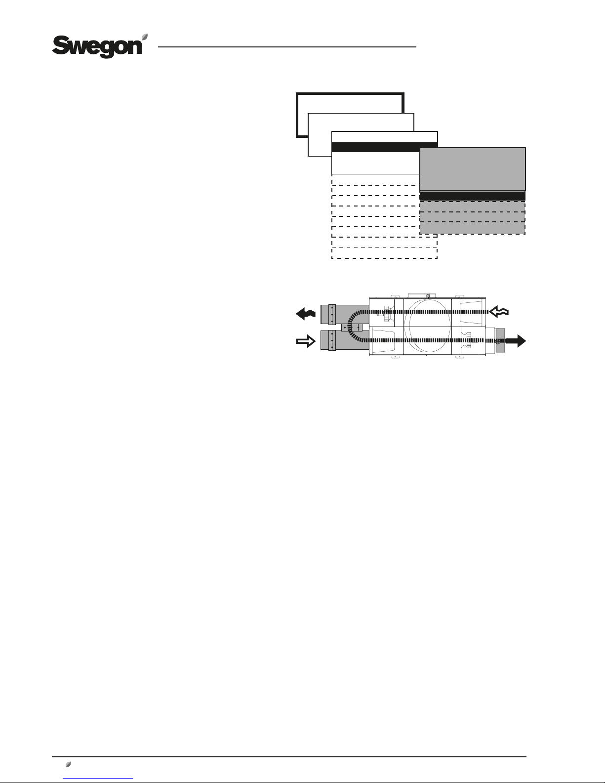
1.5 The Components of the Air Handling Unit
The individual components each specified below in a simplified and
diagrammatical description.
The air handling units are supplied in the right-hand version as shown in Fig. 1a.
Coversion to the left-hand version as shown in Fig. 1b
can be carried out by making a simple adjustment in the
control equipment.
In the left-hand version (Fig. 1b), the components marked
with an asterisk change function and designation (the
components are named according to whether they are for
supply air or extract air).
The arrangement of the components and their designations
1
OUTDOOR AIR* (Left-hand version: Extract air)
2 EXHAUST AIR* (Left-hand version: Supply air)
3 Extract air fan* with motor and motor controller
4 Pressure sensor, extract air fan* (Position on function selector
switch = 1)
5 Electrical equipm. cubicle with control unit
6 Hand-held Micro Terminal
7 Main switch/Safety switch
8 Extract air filter*
9 EXTRACT AIR* (Left-hand version: Outdoor air)
10 SUPPLY AIR* (Left-hand version: Exhaust air)
11 Supply air temp. sensor (to be mounted in supply air duct)
12 Supply air fan* with motor and motor controller
13 Extract air temperature sensor*
14 Pressure sensor, supply air fan* (Position on function selector
switch = 2)
15 Heat exchanger
16 Drive motor, heat exchanger
17 Sensor, rotation monitor
18 Outdoor air temperature sensor*
19 Mounting bracket for securing the unit in position, 4
brackets
20 Supply air filter*
21 Slide rails for the inspection panels
Left-hand version
Fig 1b
Outdoor air Supply air Extract air Exhaust air
Fig 1a
1
2
3 4
5
6
11
7
8
10
9
1213141516171820 1921
Page 5
GB.GOLDLP.170830
www.swegon.com 5
We reserve the right to alter specifications without notice.
2 SAFETY PRECAUTIONS
All staff concerned must acquaint themselves with these
instructions before beginning any work on the unit. Any
damages to the unit or parts of it due to improper handling or misuse by the purchaser or the fitter cannot be
considered subject to guarantee if these instructions have
not been followed correctly.
Warning
Only a qualified electrician or service personnel
trained by Swegon shall be permitted to modify
the air handling unit in conjunction with electrical
installations or the wiring of external functions.
2.1 Safety Isolating Switch/Main Switch
On the GOLD LP one-piece unit, the safety isolating switch
is externally positioned on the electrical equipment cubicle.
The air handling unit must normally be started and
stopped from the hand-held micro terminal; not by
switching the safety isolating switch on and off.
Always switch off the safety isolating switch before servicing the unit if not otherwise specified in the pertinent
instructions.
2.2 Risks
Warning
Before carrying out any work, make sure that the
power supply to the air handling unit has been
switched off.
Risk areas with moving parts
Typical moving parts are fan impellers and drive pulleys of
the rotary heat exchanger.
Inspection panels can only be opened using a special key,
they therefore function as safety guards for fans and the
heat exchanger. If the ducts are not connected to the fan
outlets, the outlets must be fitted with a safety guard
(wire mesh screen).
Warning
The inspection panels on the filter/fan sections must
not be opened while the unit is in operation.
Under normal operating conditions, use the stop
button on the hand-held terminal to stop the air
handling unit.
Wait until the fans have stopped rotating before
opening the inspection panel.
The air pressure inside the fan section is positive,
which means that the door can fly open.
2.3 Safety Guards
The lockable inspection panels serve as a safety guard for
the fans/heat exchanger.
The cover over the power supply unit in the electric equipment cubicle serves as a safety guard for this unit.
Only a qualified electrician or trained service technicians
shall be allowed to remove the safety guards.
Warning
The power supply to the unit shall be isolated by
switching off the safety isolating switch before
removing the safety guard.
All the inspection panels must be closed and the
cover of the electrical equipment cubicle must be
fastened while the air handling unit is operating.
Page 6

GB.GOLDLP.170830
6 www.swegon.com
We reserve the right to alter specifications without notice.
3 INSTALLATION
See the specific installation instructions.
4 COMMISSIONING
4.1 General
Sequence for commissioning:
1. Check that there are no foreign objects in unit, ducting system
or functional sections.
2. Turn the safety isolating switch to the ON position (I).
3. Select the language desired, if you have not already done so.
See Section 6.2 or 14.1.
4. The unit has factory settings which make it ready to use. See
Section 21.2 Commissioning record.
However, in many cases, these settings need to be adjusted to
suit the current installation.
Program the switch clock, operating conditions, temperatures,
airflows and functions according to the procedures in Sections
5-16.
Select whether l/s, m3/s or m3/h shall be used as the flow unit.
(INSTALLATION LEVEL in the HAND-HELD MICRO TERMINAL
menu).
Fill out the Commissioning Record and save it in the document
pocket of the unit.
5. Activate, if needed, manual or auto operation (MAIN MENU)
or lock the speed of the fans (AIR ADJUSTMENT menu).
Adjust the ducting system and air devices as described in Section
4.2.
6. Finish off with a filter calibration as described in Section 7.4.2.
Page 7
GB.GOLDLP.170830
www.swegon.com 7
We reserve the right to alter specifications without notice.
4.2 Adjusting the Duct System
and Air Devices
In order to prevent the fans from consuming more power
than necessary, it is important to keep the pressure drop in
the system as low as possible.
It is also important that ducting systems and air devices are
correctly adjusted to provide the comfort expected.
When adjusting air devices and the duct system installed
in combination with the GOLD, it is appropriate to follow
the proportionality method.
This means that the proportion between the airflows in
branch ducts stays constant even if the airflow in the main
ducts is changed. The same proportion applies to the air
devices in the installation.
When adjusting the ducting system there is provision for
locking the speed of the fans in the unit to a specific preset flow rate, see Section 6.5.
4.2.1 Adjustment Sequence
The system should be adjusted in the following order:
1. Adjust of the air devices in each branch duct.
2. Adjust the branch ducts.
3. Adjust the main ducts.
4.2.2 Adjustment Procedure
1. Set all the air devices and dampers to the fully open
position.
2. Calculate the ratio of the airflow reading to the design
airflow of all the air devices, branch ducts and main ducts.
The air device in every branch that has the lowest ratio
should be fully open. Use this air device as an INDEX AIR
DEVICE. The same applies to branch dampers and main
dampers.
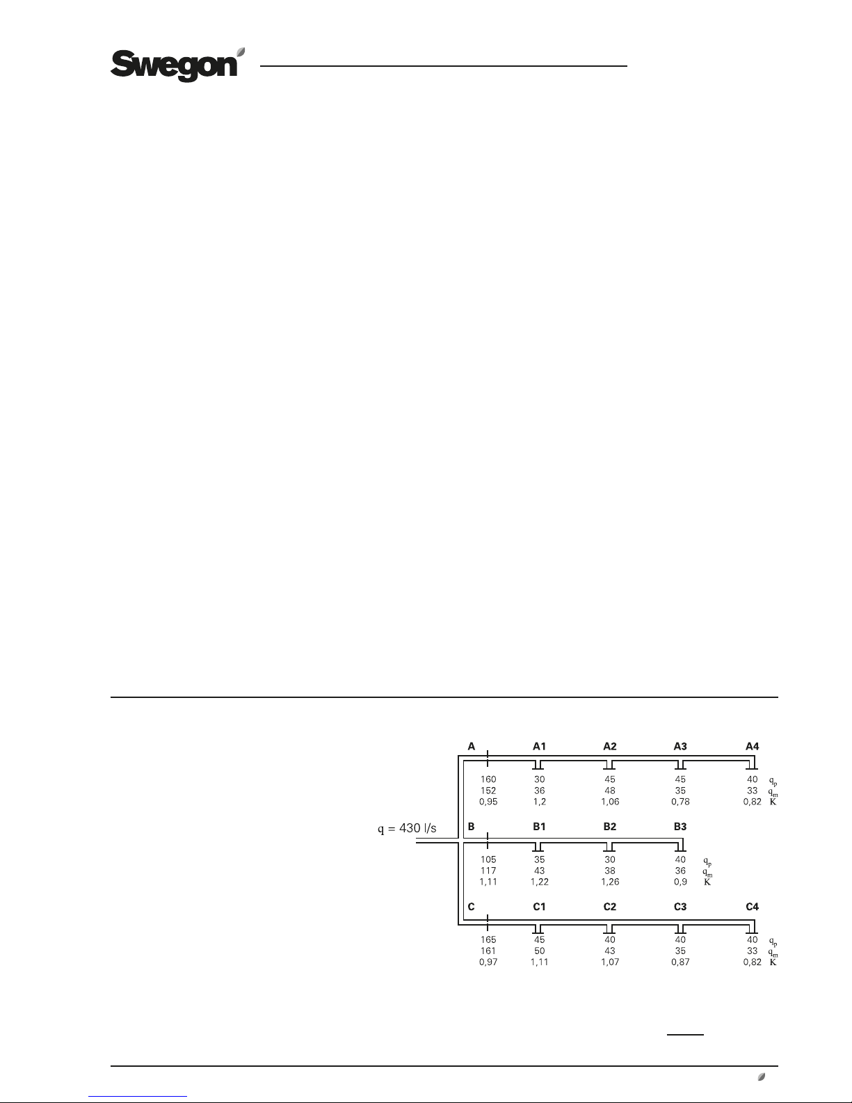
Example on how to carry out adjustments
– Start adjusting duct branch B, since this one has
the highest ratio.
– The last air device, B3, has the lowest ratio and
should be fully open.
Adjust the other air devices, B1 and B2, so that
these will have the same ratio as air device B3 (see
item 5 above).
– Now adjust the air devices in branch duct C. Air
device C4 should be fully open; throttle the others
to the same ratio.
– Adjust the air devices in branch duct A. The index
air device here is air device A3, which means that
you first throttle air device A4 (the reference device)
to device A3:s ratio.
Thereafter the others are adjusted to the same ratio
as air device A4.
– Throttle branch damper B to the same ratio as branch damper A,
throttle branch damper C to the same ratio as branch damper A.
Check that all dampers have the same ratio.
When the adjustment has been completed, 3 air devices and
one branch damper should stand fully open to obtain the lowest
possible pressure in the system.
qp = design airflow (l/s)
qm = airflow reading (l/s)
q
m
K (Ratio) =
q
p
When you’ve completed the adjustments, one air device in
every branch, one branch damper and one main damper
should consequently be fully open.
3. Start adjusting the main duct that has the highest ratio
and the branch duct in the main duct that has the highest
ratio. Starting from this point enables you to “press” the
air in front of you toward the sections of the system that
have the least air.
4. Adjust the last air device on the duct branch so that
it will have the same ratio as the index device. This air
device will serve as the REFERENCE AIR DEVICE. Often
it is the last air device on the branch that has the lowest
ratio and should be open. In this case, the same air device
serves as the index device and reference device.
5. Throttle the other air devices in the branch to the same
ratio as the reference device.
Note! The ratio in the reference device will change every
time another air device is throttled, so in practice the ratio
for the reference device can be set slightly higher. The
reference device must be measured in between each air
device throttled.
6. Go to the branch that had the next highest ratio and
adjust the air devices there, etc.
Note! All branch dampers should be fully open until all air
devices have been adjusted.
7. Throttle the branch damper that had the highest ratio
to the same ratio that the branch of the lowest ratio had.
Note! Keep in mind that the index damper changes ratio;
proceed as described in item 5.
8. When all branches have been adjusted, throttle the
main dampers in the same manner.
Also see the example below on how to carry out adjustments.
Page 8
GB.GOLDLP.170830
8 www.swegon.com
We reserve the right to alter specifications without notice.
4.3 To Adjust the Pressure Balance
4.3.1 General
There should be a certain degree of negative pressure in
the extract air section so that the direction of air leakage
through the heat exchanger and the function of the purging sector will be correct. This ensures that extract air will
not be transferred to the supply air.
The pressure balance in the unit should be adjusted when
the ventilation system has been fully installed and the
airflows discharged from all the air diffusers and registers
have been adjusted, and when the supply air and extract
airflows are as they should be while the air handling unit is
operating normally.
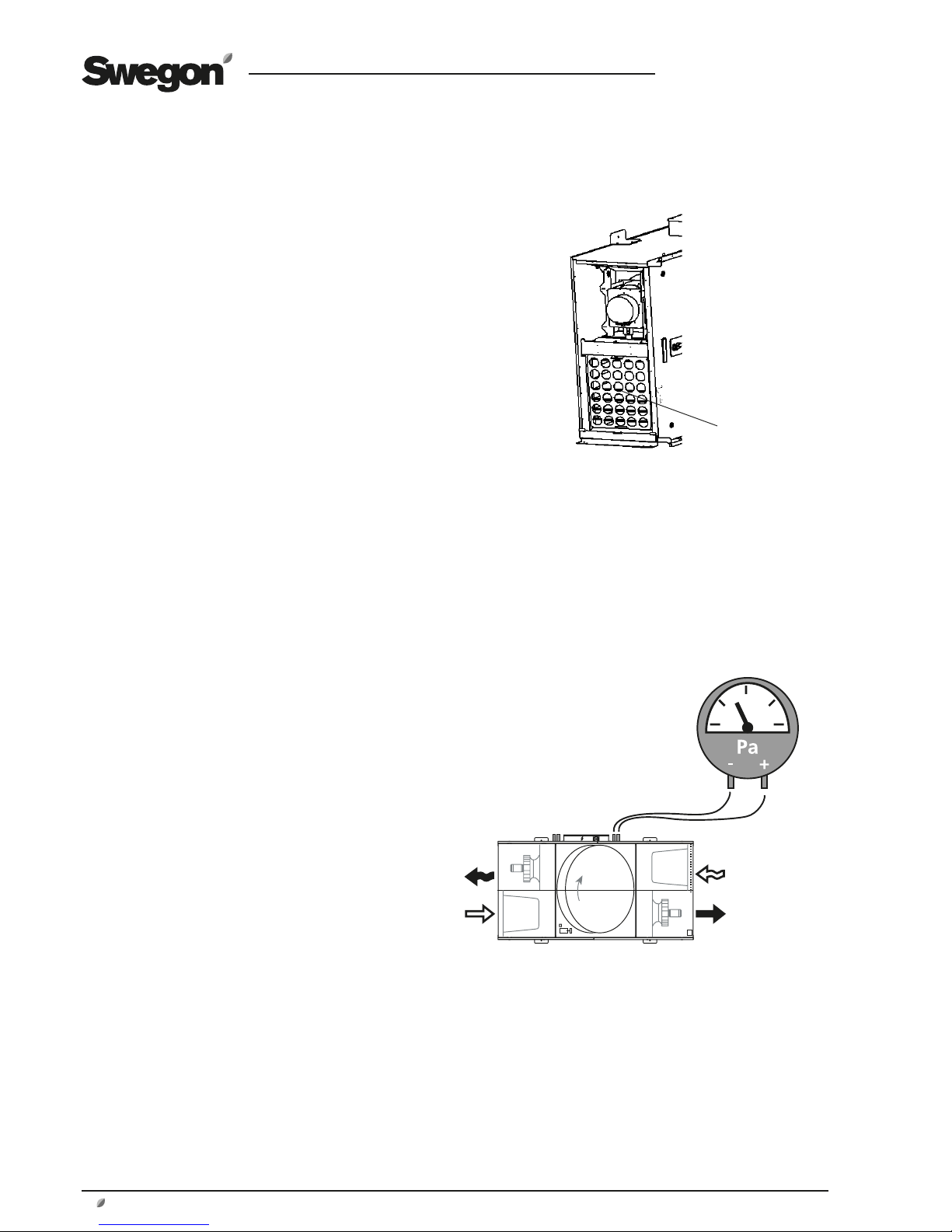
4.3.2 To Ensure the Correct Leakage Direction
The pressure balance in the AHU is adjusted by repositioning a commissioning plate mounted in the extract air inlet.
The commissioning plate is supplied separately and should
be fitted by the fitter when the extract air duct is connected. See illustration.
Connect a pressure gauge to the pressure measurement
tappings of the air handling unit. The AHU has four pressure measurement tappings. The two tappings closest
to the extract air duct should be used. The blue pressure
measurement tapping is used for measuring the negative
pressure in the extract air section and the white pressure
measurement tapping is used for measuring the negative
pressure in the supply air section.
The pressure measurement tappings are situated by the
junction hood.
Note that both pressure measurement tappings are used
for measuring negative pressure.
MEASURED VALUES
The negative pressure in the extract air section should be
greater or the same as the negative pressure in the supply
air section.
If the negative pressure in the extract air section is the
same or up to 20 Pa greater than the negative pressure in
the supply air section, then you have finished commissioning the unit.
DEVIATIONS
If the negative pressure in the extract air section is less
than that in the supply air section, then you must carry out
the following adjustment:
1. Stop the air handling unit, open the inspection door to
access the extract air filter.
Blank off an appropriate number of holes in the commissioning plate using the plastic plugs supplied.
3. Close the inspection door and restart the AHU.
4. Measure the pressures.
Repeat this procedure until the negative pressure in the
extract air section is just as great or up to 20 Pa greater
than the negative pressure in the supply air section
(0–20 Pa).
Pressure measurement tappings – leakage direction
(AHU shown in the right-hand version)
- (blue)
+ (white)
EXTRACT AIR
2
Commissioning plate
5. If the negative pressure in the extract air section is
greater than 20 Pa compared with the supply air section, although the commissioning plate is dismantled,
the leakage and purging air flow will be greater than
anticipated. This means that the actual extract air flow
will deviate from the preset extract airflow. The deviation increases as the difference in pressure increases.
Page 9

GB.GOLDLP.170830
www.swegon.com 9
We reserve the right to alter specifications without notice.
Position indicator
5 HAND-HELD MICRO TERMINAL
AND HOW TO USE THE MENUS
5.1 HAND-HELD MICRO TERMINAL
5.1.1 General
The hand-held micro terminal consists of an encapsulated
control box with a 3-metre long cable for connection to
the air handling unit by means of a quick connector.
The hand-held terminal has an illuminated display, 6 pushbuttons and a red LED for indicating alarms.
5.1.2 Buttons
The buttons have the following functions:
ENTER confirms your selection and proceeds to next
menu level.
ESCAPE reverts to the previous menu.
ADVANCE UPWARD or to the LEFT.
ADVANCE DOWNWARD or to the RIGHT.
DECREASES the value of the highlighted setting.
INCREASES the value of the highlighted setting.
5.1.3 Display Screen
The display screen has 4 lines. Many of the menus however have several lines and these are shown line for line as
you press the ADVANCE DOWNWARD button. The position indicator shows where you are in the menu.
5.1.4 Abbreviations
The following abbreviations are used in the menus
SA = Supply air (E.g. SA FAN = Supply air fan)
EA = Extract air
OUTD = Outdoor air
FV = Anti-frosting monitor
HEAT EXCH = Heat exchanger
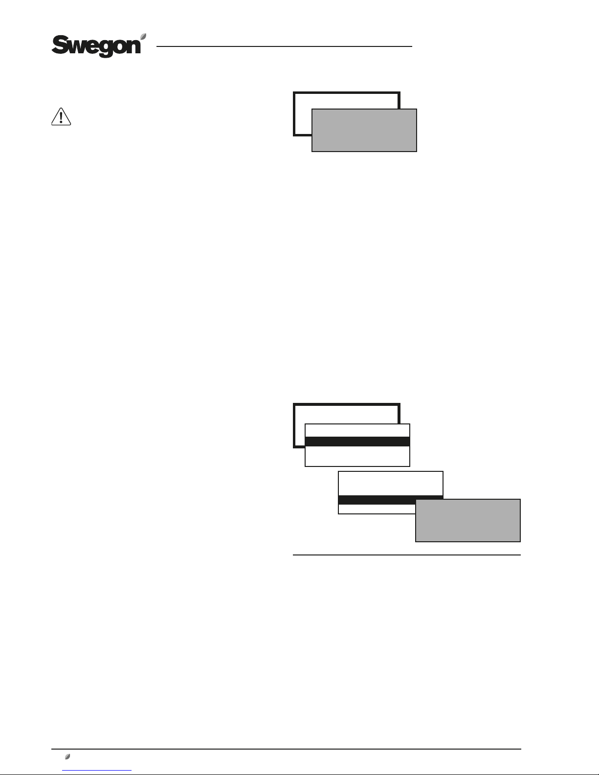
GOLD LP TUE 14:40
STOP
MANUAL OPERATION
STOP?
MAN/AUTO.OP
SETTINGS
GOLD LP TUE 14:40
STOP
MANUAL OPERATION
STOP?
Page 10
GB.GOLDLP.170830
10 www.swegon.com
We reserve the right to alter specifications without notice.
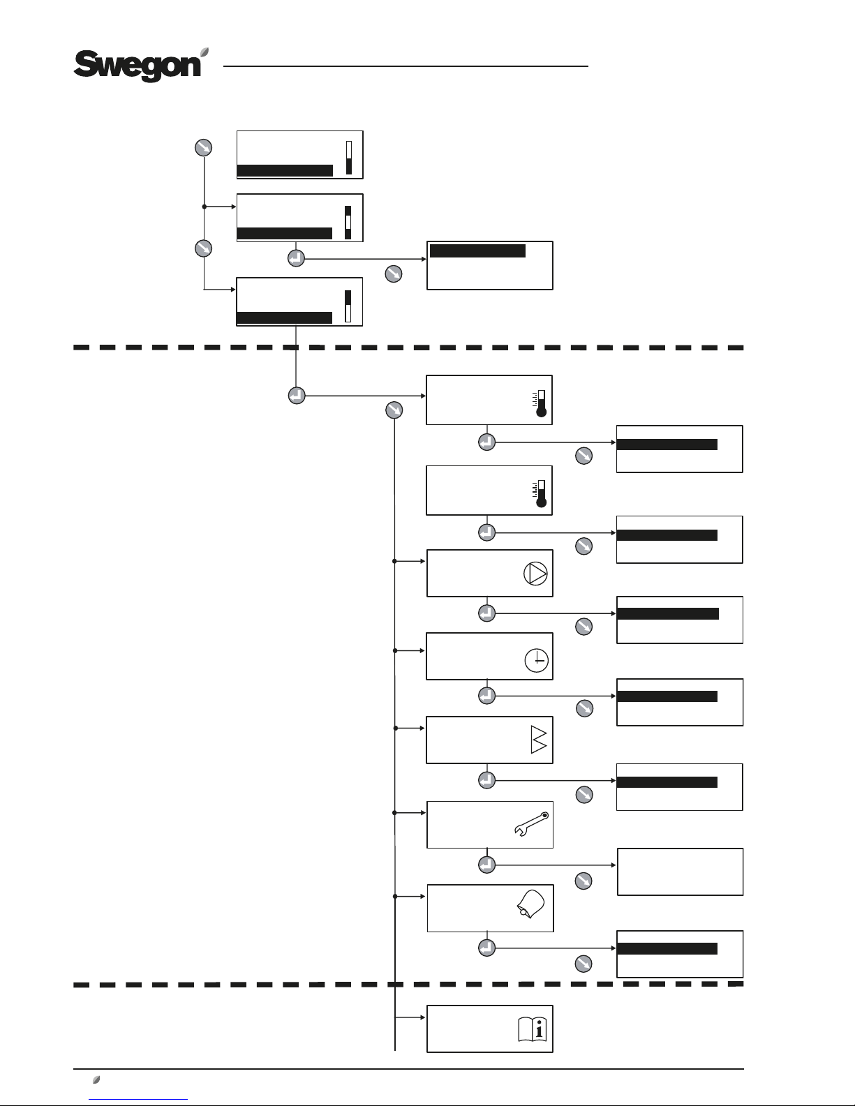
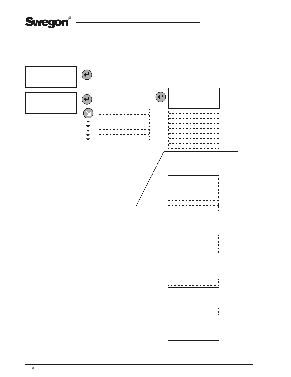
5.2 Menu tree
MAIN
MENU
(Section 6)
USER LEVEL
(Section 7)
INSTALLATION LEVEL
(Section 8-16)
GOLD LP TUE 14:40
STOP
MANUAL OPERATION
STOP?
GOLD LP TUE 14:40
MANUAL OPERATION
STOP?
MAN/AUTO.OP
GOLD LP TUE 14:40
STOP?
MAN/AUTO.OP
SETTINGS
TEMPERATURE
FLOW/PRESSURE
SWITCH CLOCK
FILTERS
AIR ADJUSTMENT
ALARMS
INSTALLATION
AUTO OPERATION
MANUAL LOW SPEED
MANUAL HIGH SPEED
*SWITCH CLOCK*
TIME/DATE
TIME CHANNEL
YEAR CHANNEL
*FILTERS*
READINGS
CALIBRATION
*AIR ADJUSTMENT*
LOCKS FAN SPEED
TIME SETTING: 0 h
*ALARMS*
ACTIVE ALARMS
ALARM HISTORY
*FLOW/PRESSURE*
READINGS
SETTINGS
Important! The appearance of
the menus varies depending
on the type of air handling
unit and functions selected.
*TEMPERATURE*
READINGS
SETTINGS
ALL YEAR COMFORT
*ALL YEAR COMFORT*
READINGS
SETTINGS
Page 11
GB.GOLDLP.170830
www.swegon.com 11
We reserve the right to alter specifications without notice.
GOLD LP TUE14:40
STOP
MANUAL OPERATION
STOP?
GOLD LP TUE14:40
MANUAL OPERATION
STOP?
MAN/AUTO.OP
AUTO OPERATION
MANUAL LOW SPEED
MANUAL HIGH SPEED
GOLD LP TUE14:40
STOP?
MAN/AUTO.OP
SETTINGS
USER LEVEL
INSTALLATION LEVEL
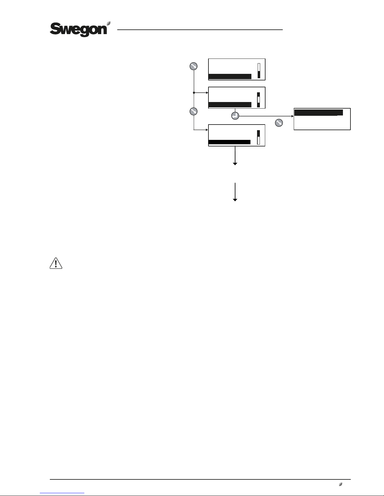
6 MAIN MENU
6.1 General
The main menu is normally shown if no other menu
has been selected.
The display automatically returns to the main menu
after 30 minutes.
The content in the menu changes depending on the
operating mode selected other functions that affect
the present operating mode and possible tripped
alarms.
6.2 Selection of Language
When the air handling unit is started up for the first
time, a language selection menu is displayed.
Select the language desired.
If you want to change language at a later oppor-
tunity – or if you’ve selected the wrong language
– you can change the language at INSTALLATION
LEVEL under HAND TERMINAL. See Section 14.1.
6.3 Changing Operating Mode
You can start and stop the air handling unit or
change over to manual or automatic operation
from the main menu.
The air handling unit should normally be
started and stopped from the hand-held
micro terminal; not by switching the safety
isolating switch on and off.
When the air handling unit is started up, menus
for the various delays that are part of the starting
sequence are shown.
See also Section 10.1.1, Starting Sequence.
6.4 Settings
When selecting SETTINGS in the main menu, you
will advance to User Level and Installation Level.
See Section 7.
Page 12
GB.GOLDLP.170830
12 www.swegon.com
We reserve the right to alter specifications without notice.
X = Extract air temperature °C
ERS Regulation 1
15
10
20
15 20
25
Step 1
Step 2
Step 3
Step 4
1
2
3
15
20
22
9
10
12 15 20 25 27
Y = Supply air temperature setpoint °C
ERS Regulation 2
7 USER LEVEL
7.1 Temperature
The basic functions can be preset at INSTALLATION LEVEL and the values can be read and set at USER LEVEL.
See also Section 9.2 in which the functions for
temperature are described in detail.
IMPORTANT! If you intend to substantially alter the tempera
ture settings, you should first stop the air handling unit before
doing so.
7.1.1 Readings
Used for checking the performance.
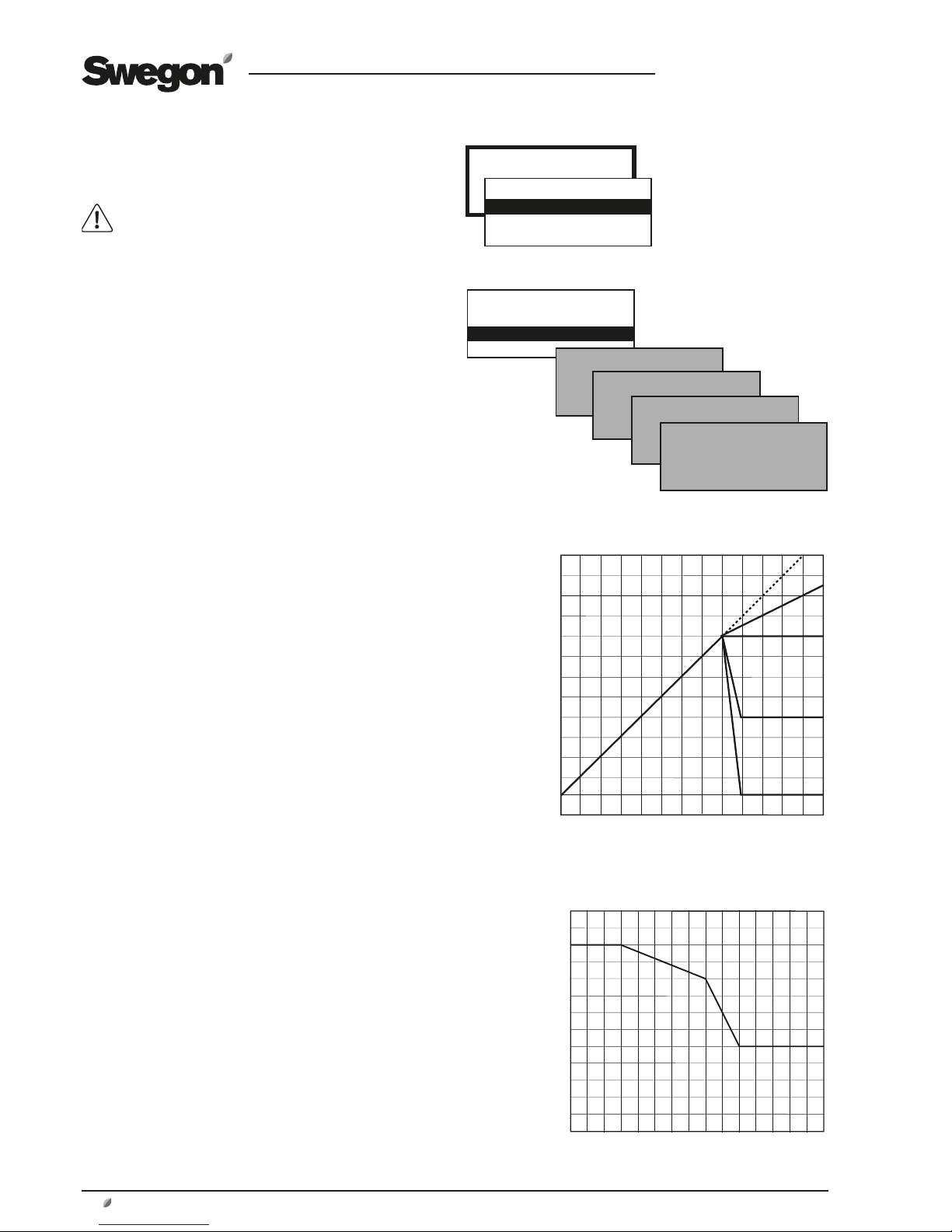
7.1.2 Settings
ERS REGULATION 1
The control unit regulates the relationship between the supply
air and the extract air temperatures according to a factory
preset curve.
Settings (see the chart to the right as well):
Value Setting Factory
range settings
Step 1 - 4 1
EA/SA Differential 1-5 °C* 2 °C
Breakpoint (refers to 15-23 °C* 20 °C
extract air temperature)
ERS REGULATION 2
The control unit regulates the relationship between the supply
air and extract air temperatures according to a custom-plotted
curve. The curve has three adjustable breakpoints.
Settings (see the chart to the right as well):
Value Setting Factory
range settings
Extract air temperature
X1 10-40 °C 15 °C
X2 10-40 °C 20 °C
X3 10-40 °C 22 °C
Supply air temperature
Y1 10-40 °C 20 °C
Y2 10-40 °C 18 °C
Y3 10-40 °C 14 °C
SUPPLY AIR REG.
Settings:
Value Setting Factory
range settings
Supply air temperature
setpoint 15-40 °C* 21.5 °C
EXTRACT AIR REG.
Settings:
Value Setting Factory
range settings
Extract air/room temp.
Setpoint 15-40 °C* 21.5 °C
Min. supply air temperature 13-25 °C* 15 °C
Max. supply air temperature 18-45 °C* 28 °C
*) The setting range can be changed. See 14.3, Min/Max
Adjustment.
Extract air temperature °C
Supply air temperature setpoint °C
Breakpoint
EA/SA differential
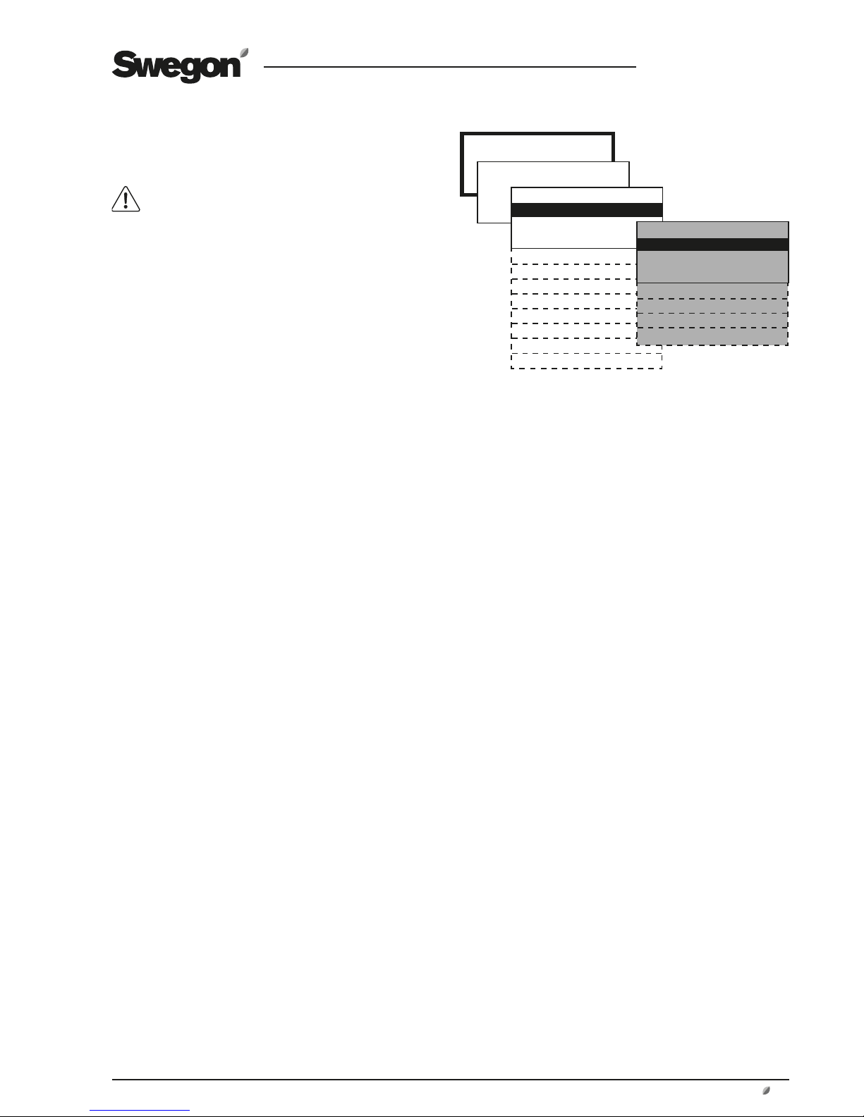
TEMPERATURE
*TEMPERATURE*
READINGS
SETTINGS
*TEMPERATURE*
READINGS
SETTINGS
ERS REGULATION 1
ERS REGULATION 2
SUPPLY AIR REG.
EXTRACT AIR REG.
Important! The
appearance of the
menus varies depending
on the type of air
handling unit and
functions selected.
Page 13
GB.GOLDLP.170830
www.swegon.com 13
We reserve the right to alter specifications without notice.
Min/Max Airflows
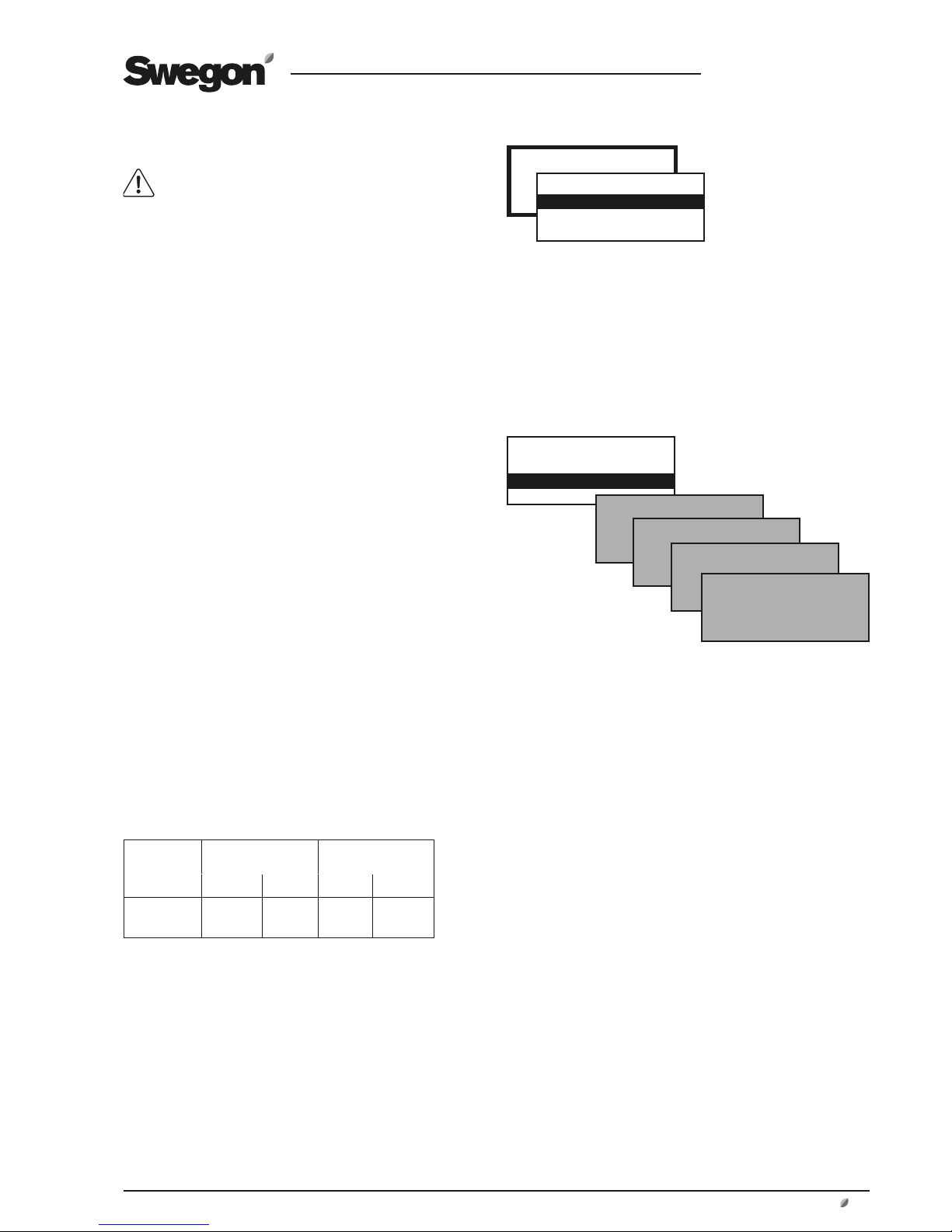
7.2 Air flow/Pressure
Basic functions are set at INSTALLATION LEVEL
and values are read and set at USER LEVEL.
Therefore see also Section 9.3, in which the func-
tions for flow/pressure are described in detail.
7.2.1 Readings
Used for performance checks.
7.2.2 Settings
The functions selected at INSTALLATION LEVEL and the
min. and max. airflows of each unit size (see the table
below) determine which values can be set.
Values for airflow (l/s, m3/s, m3/h), pressure (Pa) or input
signal strength (%) can be preset depending on the function selected.
LOW SPEED
Must always be preset! The value for low fan speed cannot be higher than the value for high speed. Low speed
can be set to 0, which means that the fan is standing still.
HIGH SPEED
Must always be preset! The value or pressure for high fan
speed cannot be lower than the value for low fan speed.
MAX SPEED
Max speed is only appropriate for functions such as pressure regulation, Heating BOOST or Cooling BOOST. The
value for max fan speed cannot be lower than the value
for high fan speed.
MIN/MAX SPEED
Min/max fan speed is only appropriate for demand-controlled operation. The lowest and highest permissible
flows are preset for each of the fans. This means that the
fans will not operate outside these limits, regardless the
load.
AIR FLOW/PRESSURE
*FLOW/PRESSURE*
READINGS
SETTINGS
*FLOW/PRESSURE*
READINGS
SETTINGS
LOW SPEED
HIGH SPEED
MAX. SPEED
MIN/MAX. SPEED
* When entering settings, round off the values to the nearest
adjustable step.
AIRFLOW MIN. FLOW
GOLD LP
MAX. FLOW
GOLD LP
SIZE
m3/h * m3/s m3/h m3/s
05 300 0.08 1900 0.53
08 720 0.20 2600 0.74
Page 14
GB.GOLDLP.170830
14 www.swegon.com
We reserve the right to alter specifications without notice.
7.3 Switch clock
Basic functions for the switch clock can be preset
at INSTALLATION LEVEL under FUNCTIONS/OPERATION and the values can be read and set at USER
LEVEL.
TIME/DATE
The current date and time can be set and adjusted whenever
required.
The switch clock automatically takes leap years into consideration.
Automatic changeover between summer time/winter time to EU
Standard has been preset.
This changeover function can be blocked at INSTALLATION LEVEL
under FUNCTIONS/OPERATION.
TIME CHANNEL
Times and days can be set when the unit is to run at high speed,
low speed or be stopped.
Eight different time channels can be set. If the same in-operation
times are to apply every day of the week (Mon-Sun), you need
only program one time channel. Different operation times for
each day of the week can be programmed by programming a
time channel for each day (Mon-Fri, Sat-Sun or Mon, Tues, Wed,
etc)
The time can be set as 00:00-00:00 if the deviating in-operation
period is desirable for the entire 24 hours period.
YEAR CHANNEL
The year channels make it possible to set deviating in-service
times for parts of the day during certain parts of the year. Eight
different year channels (yearly time schedules) can be set. The
year channels over-modulate the time channel during the hours
of the day and the days that the year channel is active. The year
channel dates indicate the dates between which the year channel shall apply and the year channel hours indicate the hours of
the day between which the year channel will steer the controller
to operate the rotary heat exchanger at a specified speed. Other
times within the year channel still apply to that time channel.
The time can be set as 00:00-00:00 if the deviating in-operation
period is desirable for the entire 24 hours period.
Functions for summer night cooling, prolonged operation, etc.,
operate also when the year channel is active.
7.4 Filters
(and anti-frosting function of rotary heat exchanger)
There are two types of filter monitoring:
Calculated filter monitoring (preset at factory) monitors the fan’s
speed increase conditional on the degree of fouling in the filter.
The calibration involves taking airflow and fan speed readings.
An alarm is initiated when the fan speed has increased by 10%
above the preset alarm limit.
Filter monitoring with a pressure sensor (accessory) measures
the pressure drop across the filter. The alarm limit is preset in Pa.
7.4.1 Readings
When reading the filter status, the first value shows current value
and the second value shows current alarm limit.
7.4.2 Calibration - Filters
The filters should be calibrated for the first time in conjunction
with commissioning, when the duct system, air devices and
eventual adjustment plates have been fitted and adjusted; after
that every time the filter media are changed.
Calibration should be activated for both the supply air and the
extract air if both filters are changed or for only for one airflow
direction if only one filter has been changed.
When filter calibration has been activated, the unit runs at high
speed for about 3 minutes.
After the filter has been calibrated, a speed increase of 10%, or
a pressure rise (= fouling of the filters) of 100 Pa is permissible,
after which an alarm is initiated indicating a fouled filter.
The alarm limit can be changed at INSTALLATION LEVEL under
ALARM SETTINGS.
7.4.3 Calibration - Rotary Heat Exchanger
If the anti-frosting function accessory for heat exchanger is installed (see 9.6.1.1) calibration can be selected from this menu.
When calibration R-HX is activated the fans are accelerated to
high speed for about 3 minutes.
SWITCH CLOCK
*SWITCH CLOCK*
TIME/DATE
TIME CHANNEL
YEAR CHANNEL
Settings:
Value Setting Factory
range setting
TIME/DATE
Day Mon-Sun Automatic
Time 00:00-23:59 Current
Date Day/Month/Year Current
TIME CHANNEL 1-8
Operation Low speed/High speed* High speed
Time 00:00-23:59 00:00-00:00
Period Not active Not active
Mon, Tues, Wed etc
Mon-Fri
Mon-Sun
Sat-Sun
YEAR CHANNEL 1-8
Operation Not active Not active
Stop/Low sp./High sp.
Time 00:00-23:59 00:00-00:00
Period From Day/Month/Year 01/01/2005
To Day/Month/Year 01/01/2005
*) Shows Stop/Low speed/High speed if this function is selected
at INSTALLATION LEVEL under FUNCTIONS/OPERATION.
FILTERS
*FILTERS*
READINGS
CALIBRATION
*FILTERS*
READINGS
CALIBRATION
*FILTER CALIBRATION*
STD.FILTER
PREFILTER
HEAT EXCHANGER
Page 15

GB.GOLDLP.170830
www.swegon.com 15
We reserve the right to alter specifications without notice.
7.5 Air Adjustment
The speed of the fans can be locked for up to 72 hours.
This is practical when making air adjustments in the duct
system and air devices.
The period desired is preset but can be interrupted earlier
by selecting STOP in the menu or by changing the time
setting to 0.
7.6 Alarms
If an alarm is initiated, this is shown in the hand-held terminal both as clear text and by a blinking red diode.
This menu enables you to read alarms quickly.
ACTIVE ALARMS
Shows alarms that are active but have not initiated an
alarm signal in the display. This applies to alarms that have
a long delay, i.e. airflow or temperature alarms.
ALARM HISTORY
The 10 most recent tripped alarms are shown.
Alarm settings can be entered at INSTALLATION
LEVEL under ALARM SETTINGS.
For complete description of alarms, see Section 18.
AIR ADJUSTMENT
*AIR ADJUSTMENT*
LOCKS FAN SPEED.
TIME SETTING: 0 h
ALARMS
*ALARMS*
ACTIVE ALARMS
ALARM HISTORY
Page 16
GB.GOLDLP.170830
16 www.swegon.com
We reserve the right to alter specifications without notice.
Section 9
Section 11
Section 12
Section 13
Section 14
Section 15
Section 16
FUNCTIONS
READINGS
MANUAL TEST
ALARM SET
HAND TERMINAL
COMMUNICATION
SERVICE LEV.
*MANUAL TEST*
TEMPERATURE
FANS
HEAT EXCHANGE
REHEAT
IN/OUTPUTS
IQnomic Plus
ALL YEAR COMFORT
*READINGS*
TEMPERATURE
FANS
HEAT EXCHANGE
REGULATION SIGNALS
IN/OUTPUTS
HUMIDITY
IQnomic Plus
ALL YEAR COMFORT
OPERATION TIME
PROGRAMVERSIONS
*ALARM SETTINGS*
FIRE ALARM
EXTERNAL ALARMS
ALARM LIMITS
ALARM PRIORITY
*HAND TERMINAL INST*
LANGUAGE
AIR FLOW UNIT
MIN/MAX SETTING
BASE SETTINGS
*COMMUNICATION*
EIA-485
ETHERNET
*SERVICE LEV.*
CODE: 0000
INSTALLATION
8 INSTALLATION LEVEL
8.1 Menu Survey
*FUNCTIONS*
TEMPERATURE
AIR FLOW/PRESSURE
FILTER
OPERATION
HEATING
COOLING
HUMIDITY
IN/OUTPUTS
IQnomic Plus
ALL YEAR COMFORT
OPTIMIZE
Section 10
Automatic functions
*INSTALLATION*
CODE: 0000
Code = 1111
Important! The appearance of
the menus varies depending
on the type of air handling
unit and functions selected.
Page 17
GB.GOLDLP.170830
www.swegon.com 17
We reserve the right to alter specifications without notice.
INSTALLATION
FUNCTIONS
9 FUNCTIONS
9.1 Temperature
Basic functions can be set at INSTALLATION LEVEL
and values are read and set at USER LEVEL.
IMPORTANT! If you intend to substantially alter the temperature settings, you should first stop the air handling
unit before doing so.
9.2 Temperature Regulation
Select ERS Regulation, Supply air regulation or Extract air
regulation.
If ERS Regulation is selected, select between 1 and 2.
Control sequence for ERS regulation and Supply air regulation:
1. The temperature efficiency of the air handling unit’s
heat exchanger is modulated to provide max. heat
recovery.
2. After that the air heater, if installed, will begin to
generate heat.
3. If a downstream heating coil is not installed, or if the
its output is not adequate, the supply air fan will be
automatically and variably downspeed-regulated to
convey air at a lower flow rate.
A neutral zone can be preset, which allows a lower supply
air temperature setpoint before regulation to a lower flow
rate begins. See 8.3.4
When the supply airflow is regulated to a lower rate, the
heat exchanger will have ”excess heat”, i.e. warm extract
air, giving it capacity to maintain the supply air temperature required.
As the supply airflow is regulated to a lower rate, the air
pressure in the premises will become negative and this will
instead cause outdoor air to be sucked in through leakage spots such as doors and windows. This outdoor air
will then be heated by the ordinary heating system of the
premises.
Downspeed regulation to lower the airflow rate occurs
from the current preset flow (high speed or low speed),
down to half of this flow rate. The degree of regulation
to a lower rate is also limited by the min flow setting of
the unit. When preset flow for low speed is near the min
flow rate, the effect of this regulation to a lower rate will
be small.
Control sequence for Extract air regulation:
1. The temperature efficiency of the air handling unit’s
heat exchanger is modulated to provide max. heat
recovery.
2. After that, the re-heating coil, if installed, will begin
to generate heat.
Important! The
appearance of
the menus varies
depending on the type
of air handling unit
and functions selected.
* TEMPERATURE *
TEMPERATURE REG
OUTDOOR TEMP COMP
SUMMER NIGHT COOL
INTERM. NIGHT HEAT
MORNING BOOST
SETPOINT TEMP DISPL
EXT. SENSORS
*FUNCTIONS*
TEMPERATURE
AIR FLOW/PRESSURE
FILTER
OPERATION
HEATING
COOLING
HUMIDITY
IN/OUTPUTS
IQnomic Plus
ALL YEAR COMFORT
OPTIMIZE
Page 18

GB.GOLDLP.170830
18 www.swegon.com
We reserve the right to alter specifications without notice.
15
10
20
15 20
25
FRT-reglering 1
Extract air temperature °C
Supply air temperature setpoint °C
Step 1
Step 2
Breakpoint
EA-/SA differential
Step 3
Step 4
FRT-reglering 19.2.1.1 ERS Regulation
ERS regulation means Extract air temperature-Related
Supply air temperature regulation. This means that the
temperature of the supply air is regulated in relation to the
temperature of the extract air. Under normal circumstances, the supply air temperature is regulated to be a few degrees lower than the extract air temperature. In this way,
the heat exchanger will provide optimal performance, and
this means excellent operating economy. ERS regulation is
suitable for use when there is excess heat in the premises
generated, for example, by machinery, lighting or people
and the supply air devices in the premises are suitable diffusing air below room temperature.
ERS REGULATION 1
The control unit regulates the relationship between the
supply air and extract air temperatures according to a
factory-preset curve.
See the chart to the right.
The steps, breakpoint and EA/SA differential plotted in
the curve can be changed at USER LEVEL under TEMPERATURE/SETTINGS.
Settings:
Value Setting Factory
range setting
Step 1 – 4 1
Breakpoint 15-23 °C 20 °C
(refers to extract air temp.)
EA/SA-Differential 1-5 °C 2 °C
The setting range for the breakpoint and EA/SA differential is limited by the Min. and Max. settings at INSTALLA-
TION LEVEL under HAND TERMINAL.
ERS REGULATION 2
This is used when special needs and conditions are such
that the factory preset ERS regulation 1 curve cannot provide the results required. Conditional on which settings are
made, it may be necessary to install a post-heating coil.
An individually adapted curve regulates the relationship
between the supply air and extract air temperature.
See the chart to the right.
The following settings are possible at USER LEVEL under
TEMPERATURE/SETTINGS:
Value Setting Factory
range setting
Extract air temperature
X1 10-38 °C 15 °C
X2 11-39 °C 20 °C
X3 12-40 °C 22 °C
Supply air temperature setpoint
Y1 10-40 °C 20 °C
Y2 10-40 °C 18 °C
Y3 10-40 °C 14 °C
The setpoint displacement and summer night cooling
functions can also affect the preset temperatures.
Breakpoints according to factory setting means:
If the extract air temperature is below 15 °C (X1) the setpoint for supply air temperature is constant 20 °C (Y1).
If the extract air temperature is 20 °C (X2) the supply air
temperature set point will be 18 °C (Y2).
If the extract air temperature is above 22 °C (X3), the
supply air temperature setpoint will be constantly 14 °C
(Y3).
Factory setting means:
If the extract air temperature is below 20 °C (breakpoint),
the supply air temperature setpoint will be automatically
regulated to be 2 °C (EA/SA differential) lower.
If the extract air temperature is above 20 °C, the supply
air temperature setpoint will follow the curve according to
Step 1.
1
2
3
15
20
22
9
10
12 15 20 25 27
X = Extract air temperature °C
Y = Setpoint supply air temperature °C
ERS regulation 2
Page 19

GB.GOLDLP.170830
www.swegon.com 19
We reserve the right to alter specifications without notice.
9.2.1.2 Supply Air Regulation
Supply air regulation involves keeping a constant supply
air temperature without consideration to the load in the
premises.
This type of regulation can be used when the load and
temperatures of the premises are predictable. In most
cases a reheating coil needs to be installed; possibly a
cooling coil as well.
The following settings can be entered at USER LEVEL under TEMPERATURE/SETTINGS:
Value Setting Factory
range setting
Supply air temperature setpoint 15-40 °C 21.5 °C
Setting range for the setpoint is limited by Min. and Max.
settings at INSTALLATION LEVEL under HAND TERMINAL.
9.2.1.3 Extract Air Regulation
Extract air regulation involves keeping a constant temperature in the extract air duct (premises), by regulating the
supply air temperature. This provides a uniform temperature in the premises regardless of the load and this type
of regulation requires the installation of a reheating coil;
possibly a cooling coil as well.
The extract air temperature is measured by the temperature sensor inside the GOLD unit.
If this internal temperature sensor does not give an adequate representative extract air temperature readings,
an external room temperature sensor can be installed and
wired to the control unit’s connection marked “Internal
Bus-1”.
The following settings can be entered at USER LEVEL under TEMPERATURE/SETTINGS:
Value Setting Factory
range setting
Extract air-/room temp. setpoint 15-40 °C 21.5 °C
Min. Supply air temperature 13-18 °C 15 °C
Max. Supply air temperature 25-45 °C 28 °C
Setting range for the various values is limited by Min. and
Max. settings at INSTALLATION LEVEL under HAND TERMINAL.
Page 20
GB.GOLDLP.170830
20 www.swegon.com
We reserve the right to alter specifications without notice.
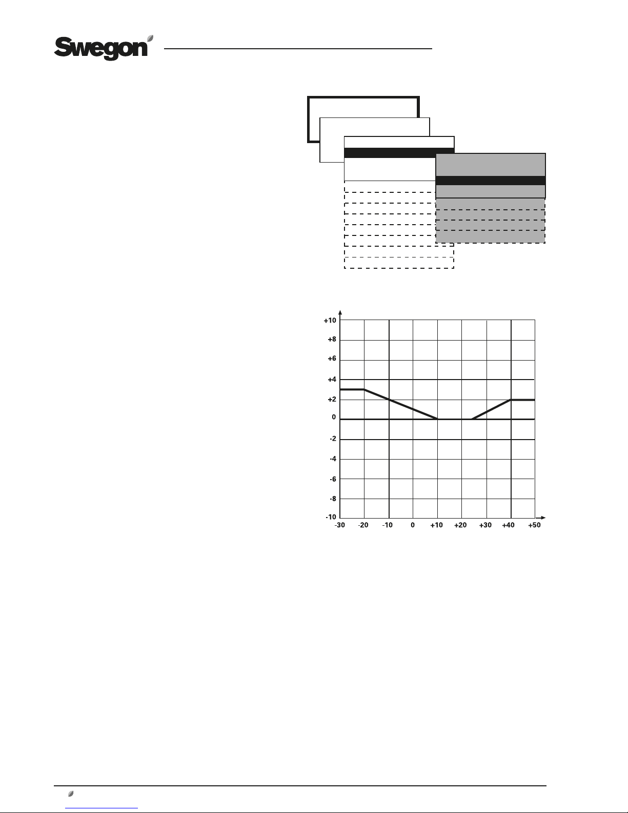
Y = Temperature displacement °C
9.2.2 Outdoor Temperature Compensation
Temperature
Outdoor temperature compensation can be activated if
the premises are abnormally subjected to the effects of
seasonal cold air or hot air due to leakage through large
windows, for instance.
The supply air temperature setpoint is compensated if the
air handling unit is operating in the supply air regulation
mode, and the extract air temperature setpoint is compensated if the air handling unit is operating in the extract air
regulation mode. This function will have no effect if the
unit is operating in the ERS regulation mode.
The preset temperature setpoint is influenced if the outdoor temperature drops below the preset X2 breakpoint
(winter compensation) and above the preset X3 breakpoint (summer compensation).
See the chart to the right.
It is possible to set negative summer compensation.
Settings:
Value Setting Factory
range setting
Winter compensation
Temperature displacement Y1 +0 – +20 °C +3 °C
Breakpoint X1 -30 – -10 °C -20 °C
Breakpoint X2 -10 – +15 °C +10 °C
Summer compensation
Breakpoint X3 +15 – +25 °C +25 °C
Breakpoint X4 +25 – +40 °C +40 °C
Temperature displacement Y2 -10 – +20 °C +2 °C
X = Outdoor temperature °C
X1
Y1
X2 X3
X4
Y2
Outdoor temperature compensation
Winter compensation in accordance with factory setting
involves:
Outdoor temperature +10 °C (Breakpoint X2): Compensation starts and gradually takes place between 0–3 °C
down to outdoor temperature -20 °C.
Outdoor temperature -20 °C (Breakpoint X1): Constant
compensation takes place with 3 °C (temperature displacement Y1).
Summer compensation in accordance with factory setting
involves:
Outdoor temperature +25 °C (Breakpoint X3): Compensation starts and gradually takes place between 0–2 °C up to
outdoor temperature +40 °C.
Outdoor temperature +40 °C (Breakpoint X4): Constant
compensation takes place with 2 °C (temperature displacement Y2).
INSTALLATION
FUNCTIONS
*FUNCTIONS*
TEMPERATURE
AIR FLOW/PRESSURE
FILTER
OPERATION
HEATING
COOLING
HUMIDITY
IN/OUTPUTS
IQnomic Plus
ALL YEAR COMFORT
OPTIMIZE
* TEMPERATURE *
TEMPERATURE REG
OUTDOOR TEMP COMP
SUMMER NIGHT COOL
INTERM. NIGHT HEAT
MORNING BOOST
SETPOINT TEMP DISPL
EXT. SENSORS
Page 21

GB.GOLDLP.170830
www.swegon.com 21
We reserve the right to alter specifications without notice.
INSTALLATION
FUNCTIONS
*FUNCTIONS*
TEMPERATURE
AIR FLOW/PRESSURE
FILTER
OPERATION
HEATING
COOLING
HUMIDITY
IN/OUTPUTS
IQnomic Plus
ALL YEAR COMFORT
OPTIMIZE
9.2.3 Summer Night Cooling
The lower temperature at night is utilised to cool down
the building structure. This reduces the cooling load
during the first hours of the day. If a cooling unit is installed, its in-operation hours will be minimised, thus offering
savings. If no cooling unit is installed, a certain cooling
effect will still be realised.
When summer night cooling function is activated, the unit
fans operate at high speed, with a supply air setpoint of
10°C, from the preset time until the conditions necessary
for stop are satisfied.
Conditions to be met to start summer night cooling at the
preset time:
• The extract air temperature should be higher than the
preset value
• The extract air should be at least 2°C warmer than the
outdoor air.
• The outdoor temperature should be above the preset
value.
• Heating has not been required between 12.00–23.00
hours.
• The unit must not operate in the high speed mode or
be stopped from an external source or manually from the
hand-held micro terminal.
Conditions to be met to stop summer night cooling at the
preset time:
• The extract air temperature drops below the preset
value.
• The outdoor temperature drops below the preset value.
• Switch clock or external input calls for high speed.
• The extract air is less than 1 °C warmer than the outdoor
air.
The function starts once per set time period.
Settings:
Value Setting Factory
range setting
Extract air temperature for start 17 - 27 °C 22 °C
Extract air temperature for stop 12 - 22 °C 16 °C
Outdoor temperature for stop 5 - 15 °C 10 °C
Supply air setpoint 10 - 20 °C 10 °C
Operating period 00:00-00:00 23:00-06:00
* TEMPERATURE *
TEMPERATURE REG
OUTDOOR TEMP COMP
SUMMER NIGHT COOL
INTERM. NIGHT HEAT
MORNING BOOST
SETPOINT TEMP DISPL
EXT. SENSORS
Page 22
GB.GOLDLP.170830
22 www.swegon.com
We reserve the right to alter specifications without notice.
INSTALLATION
FUNCTIONS
*FUNCTIONS*
TEMPERATURE
AIR FLOW/PRESSURE
FILTER
OPERATION
HEATING
COOLING
HUMIDITY
IN/OUTPUTS
IQnomic Plus
ALL YEAR COMFORT
OPTIMIZE
9.2.4 Intermittent Night-time Heating
The unit is utilised to heat the premises when it is normally
stopped by the switch clock.
The function requires that an external room sensor is
connected and that the air handling unit is provided with
air heater for reheating the air. Connect the TBLZ-1-24-2
Room sensor by means of the modular cable supplied, to
an optional connection marked Internal BUS 1. The capacity of the function will be best if the GOLD is provided with
a recirculation damper (not Swegon supply) and a shut-off
damper for outdoor air and exhaust air.
When the function is activated, the air handling unit detects when the room temperature drops below the preset
start temperature. The unit starts with preset flows and
the supply air temperature setpoint.
If extract air fan operation is not desirable, the extract
airflow can be set to 0.
The damper output can be set to 0. This means that the
connected dampers (such as shut-off dampers for outdoor
air and extract air) will not be affected. These dampers are
normally closed when the air handling unit is stopped and
they also remain closed.
At the same time, the damper in the air recirculation section, if included, will open.
Conditions to be met for intermittent night-time heating
to start:
• The unit should operate in a time channel/switch clock
stop.
• The room temperature should be below set start temperature.
Conditions to be met for intermittent night-time heating
to stop:
• High speed or external/manual stop should be activated.
• Room temperature should be above the preset stop
temperature.
• Alarm with preset stop priority has tripped.
If the needed, the air handling unit fans will continue to
operate to cool the electric air heater although other conditions for stop have been met.)
Settings:
Value Setting Factory
range setting
Room temperature for start 5 - 25 °C 16 °C
Room temperature for stop 5 - 25 °C 18 °C
Supply air temperature setpoint 10 - 40 °C 28 °C
Supply airflow *) m3/s/Pa **) m3/s/Pa
Extract airflow *) m3/s/Pa 0 m3/s/Pa
Damper output 0=not activated 0
1= activated
Control output 0=IQnomic 0
1 =IQnomic Plus
*) The setting range is the same as the min/max settings of the
air handling unit.
**) According to the setting for low speed at USER LEVEL under
FLOW/PRESSURE.
EXTRACT AIR
SUPPLY AIR
Intermittent night-time heating with air recirculation
section:
If the extract airflow is set to 0 and the damper output is
not activated, the following takes place:
When conditions for start are met, outdoor air and exhaust air shut-off dampers remain closed. The damper in
the air recirculation section is opened. The extract air fan
is idle.
The supply air fan operates according to the preset supply
airflow and the heating coil downstream of the air handling unit operates according to the supply air temperature
setpoint, until the conditions for stop are met.
* TEMPERATURE *
TEMPERATURE REG
OUTDOOR TEMP COMP
SUMMER NIGHT COOL
INTERM. NIGHT HEAT
MORNING BOOST
SETPOINT TEMP DISPL
EXT. SENSORS
Page 23

GB.GOLDLP.170830
www.swegon.com 23
We reserve the right to alter specifications without notice.
INSTALLATION
FUNCTIONS
*FUNCTIONS*
TEMPERATURE
AIR FLOW/PRESSURE
FILTER
OPERATION
HEATING
COOLING
HUMIDITY
IN/OUTPUTS
IQnomic Plus
ALL YEAR COMFORT
OPTIMIZE
INSTALLATION
FUNCTIONS
*FUNCTIONS*
TEMPERATURE
AIR FLOW/PRESSURE
FILTER
OPERATION
HEATING
HUMIDITY
COOLING
IN/OUTPUTS
IQnomic Plus
ALL YEAR COMFORT
OPTIMIZE
9.2.5 Morning BOOST
The unit is utilised to heat the premises during a preset
period prior to the switch-in time set on the switch clock.
The function is used if the air recirculation section is installed.
The unit starts early and uses the same operation and
temperature regulation settings as it would at the regular
start time.
If the extract air fan is not required to operate, the extract
airflow can be set to 0.
Damper output can be set to be inactive. This means that
connected dampers (e.g. outdoor air and exhaust air shutoff dampers) are not affected. Normally these dampers
are closed when the unit is stopped and thus they remain
closed.
At the same time, the damper in the air recirculation section, if included, will open.
Settings:
Value Setting Factory
range setting
Time for start prior to regular
start time according to switch clock hour, min.
00:00
Damper output Inactive Inactive
Extract air fan Inactive Inactive
FL/Rum-temp 10 - 30 °C 22 °C
TL-min 8 - 20 °C 15 °C
TL-max 16 - 50 °C 28 °C
Settings:
Value Setting range Factory setting
External Extract air/Room Inactive//IQnomic
Communication
Inactive
External Outdoor Inactive//IQnomic
Communication
Inactive
Alarms 0 - 9990 min. 5 min.
* TEMPERATURE *
TEMPERATURE REG
OUTDOOR TEMP COMP
SUMMER NIGHT COOL
INTERM. NIGHT HEAT
MORNING BOOST
SETPOINT TEMP DISPL
EXT. SENSORS
* TEMPERATURE *
TEMPERATURE REG
OUTDOOR TEMP COMP
SUMMER NIGHT COOL
INTERM. NIGHT HEAT
MORNING BOOST
SETPOINT TEMP DISPL
EXT. SENSORS
9.2.6 Setpoint Temperature Displacement
Used for changing the supply air and extract air temperature setpoints by means of an external 0-10 VDC signal
(control unit terminals 35 (-), 37 (+)). The temperature can
be increased or decreased at certain times of the day by
means of an external switch clock or potentiometer, for
instance.
The setpoint can be influenced ±5 °C.
If the unit is operating in the supply air regulation mode,
the supply air temperature is displaced and if the unit is
operating in the extract air regulation mode, the extract
air temperature is displaced.
When the unit is operating in the ERS regulation 1 mode,
the difference between extract air and supply air is influenced. The difference cannot be less than 0 °C. The difference will decrease as the input signal increases.
If the unit is operating in the ERS regulation 2 mode, the
supply air setpoint will be offset.
When the function is activated, the setpoint is offset as
illustrated in the chart to the right.
1050
+5
+4
+3
+2
+1
0
-1
-2
-3
-4
-5
Setpoint temp displacement °C
Control signal V DC
Setpoint temp displacement involves:
Control signal 0 V DC: The setpoint is lowered by 5 °C.
Control signal 5 V DC: Unchanged setpoint.
Control signal 10 V DC: The setpoint is increased by 5 °C.
Settings:
Value Setting Factory
range setting
Setpoint temp displacement Inactive/active Inactive
Page 24
GB.GOLDLP.170830
24 www.swegon.com
We reserve the right to alter specifications without notice.
9.2.7 External Temperature Sensors
The IQnomic control unit has provision for wiring an
external room sensor and/or external outdoor sensor. The
sensor can be used when the internal sensor of the unit
does not provide representative values.
External Extract air/Room can measure the extract air
temperature in a larger room instead of the temperature
inside the air handling unit.
External Outdoor measures the outdoor air temperature
outdoors, instead of the temperature inside the air handling unit.
Connect the TBLZ-1-24-2 sensor by means of the modular
cable supplied, to an optional connection marked Internal
BUS 1.
Sensor TBLZ-1-24-2 can be used both as a room sensor
and an outdoor sensor. They must therefore be addressed
according to function using the function selector switch
on the sensor. The function selector switch must be in
Position 1 if the sensor is used as a room sensor and in
Position 2 if it is used as an outdoor sensor.
If the TBLZ-1-24-2 sensor is installed outdoors, it must be
mounted inside an air-tight enclosure.
As an alternative, a temperature reading can be communicated to the air handling via communication from e.g. a
main system.
The alarm setting indicates how long the alarm will be
delayed if communication is lost.
INSTALLATION
FUNCTIONS
*FUNCTIONS*
TEMPERATURE
AIR FLOW/PRESSURE
FILTER
OPERATION
HEATING
HUMIDITY
COOLING
IN/OUTPUTS
IQnomic Plus
ALL YEAR COMFORT
OPTIMIZE
* TEMPERATURE *
TEMPERATURE REG
OUTDOOR TEMP COMP
SUMMER NIGHT COOL
INTERM. NIGHT HEAT
MORNING BOOST
SETPOINT TEMP DISPL
EXT. SENSORS
Page 25

GB.GOLDLP.170830
www.swegon.com 25
We reserve the right to alter specifications without notice.
INSTALLATION
FUNCTIONS
*FUNCTIONS*
TEMPERATURE
AIR FLOW/PRESSURE
FILTER
OPERATION
HEATING
COOLING
HUMIDITY
IN/OUTPUTS
IQnomic Plus
ALL YEAR COMFORT
OPTIMIZE
* AIRFLOW/PRESSURE *
SA FAN REGULATION
EA FAN REGULATION
CLEAN AIR CONTROL
OUTDOOR TEMP COMP.
SA DOWN REGULATION
SLAVE CONTROL
* AIRFLOW/PRESSURE *
SA FAN REGULATION
EA FAN REGULATION
CLEAN AIR CONTROL
OUTDOOR TEMP COMP.
SA DOWN REGULATION
SLAVE CONTROL
Settings:
Value Detting
Fan regulation (SA/EA) Flow regulation
Pressure regulation
Demand control
Slave control
9.3 Flow/Pressure
Basic functions are set at INSTALLATION LEVEL and
the values are read and set at USER LEVEL.
9.3.1 Fan Regulation
The type of regulation used for the supply air fan and the
extract air fan respectively can be selected individually.
9.3.1.1 Flow Regulation
Flow regulation involves operating the air handling unit
to keep the preset airflow constant. The speed of the fans
is automatically regulated to provide correct airflow even
if the filters begin to become clogged, air devices are
blocked, etc.
Constant airflow is advantageous, since the airflow always
is exactly as it was from the beginning.
It should however be noted that everything that increases
the pressure drop in the ventilation system, such as the
blocking of air devices and dust accumulating in the filters, causes the fans to run at a higher speed. This causes
higher power consumption and may also cause discomfort
in the form of noise.
9.3.1.2 Pressure Regulation
The airflow automatically varies to provide constant pressure in the ducting. This type of regulation is also called
VAV regulation (Variable Air Volume).
Pressure regulation is used when damper operations increase the air volume in parts of the ventilation system.
The duct pressure is measured by an external in-duct pressure transducer which is wired to the BUS communication
of the control unit. The setpoint setting required (separate
for low speed and high speed) is entered in Pa.
The function can be limited so that the fan speed will not
exceed the preset max. permissible values.
9.3.1.3 Demand Control
The flow demand is regulated via a 0-10 V input signal
from an external sensor, such as a carbon dioxide sensor
that is wired to control unit terminals 35(-) and 37(+). The
required setpoint (separate for low speed and high speed)
is set as a percentage of the input signal.
The function can be limited so that the flow will not be
higher or lower than the preset max. and min. permissible
values respectively.
9.3.1.4 Slave Control
The flow is constantly regulated to be the same from the
one fan as from the other fan. If one fan is pressure-controlled or demand-controlled, the other one can be controlled as a slave to generate the same airflow.
The performance of the fan controlled as a slave can be
restricted if its maximum flow is set to a lower airflow rate.
Both fans cannot be controlled as slaves. If both are selected by mistake, the extract air fan will be forced to operate
in the flow regulation mode.
Page 26

GB.GOLDLP.170830
26 www.swegon.com
We reserve the right to alter specifications without notice.
INSTALLATION
FUNCTIONS
*FUNCTIONS*
TEMPERATURE
AIR FLOW/PRESSURE
FILTER
OPERATION
HEATING
COOLING
HUMIDITY
IN/OUTPUTS
IQnomic Plus
ALL YEAR COMFORT
OPTIMIZE
9.3.1.5 Clean Air Control
The Clean Air Control function is used in ventilation systems where the aim is to regulate the airflow according to
the content of emission/impurities in the room air.
The accessory VOC sensor (Volatile Organic Compounds)
TBLZ-1-60-1-1 or TBLZ-1-60-2-2 is required. The VOC
sensor measures the content of emissions/impurities in %
VOC. See the separate installation instructions for each
VOC sensor.
When an occupant emits CO
2
, this creates a proportional
amount of emissions/impurities which are measurable by
the VOC sensor. For an approximate translation of the %
VOC to CO2 content, see the diagram.
When the air handling unit is powered up for the first
time, initialisation of the analogue VOC sensor TBLZ-1-601-1 (part no. 328964-01) occurs. During this initialisation
the VOC sensor provides a fixed signal of approximately
50% VOC for 6 hours. Other VOC sensors are initialised
at the factory. If the unit at a later time is de-energised,
and is subsequently reenergised, the sensor is reinitialised
for 15 minutes (provided that initialisation during the first
energising occasion was not interrupted).
When the VOC sensor measures contents of emissions/
impurities that are lower than the preset value; the air
handling unit’s supply air and extract air flows are then
equivalent to the preset min. flows. When the VOC sensor
instead measures contents of emissions/impurities that are
higher than the preset value, the supply air and extract air
flows are variably increased until the preset value or max.
flow is reached.
When the Clean Air Control function is activated, the fan
regulation modes are automatically selected (extract air
fan demand controlled, supply air fan slave controlled).
Later on, they can only be read under Functions in the
menu.
Settings:
Value Setting Factory
range setting
Clean Air Control Inactive/Active Inactive
VOC sensor Analogue/Bus**** Bus
VOC low speed 10 - 90 % 50 %
VOC high speed 10-90 % 30 %
Min. flow * m3/s 0.08/0.20 m3/s**
Max. flow * m3/s 0.53/0.74 m3/s***
*) The setting range is the same as the min. - max. settings of the
air handling unit.
** Size 05 = 0.08 m3/s, Size 08 = 0.20 m3/s
*** Size 05 = 0.53 m3/s, Size 08 = 0.74 m3/s
**** Analogue = TBLZ-1-60-1-1. Bus = TBLZ-1-60-2-2.
1000
1500
2000
400
10 20 30 40 50 60 70 80 90
% VOC
CO
2
content, ppm
Example:
800 ppm is equivalent to approx. 30% VOC.
If influenced by other emissions/impurities in the air, such
as cooking odours, cigarette smoke, etc., the VOC content
increases in relation to the CO
2
content.
* AIRFLOW/PRESSURE *
SA FAN REGULATION
EA FAN REGULATION
CLEAN AIR CONTROL
OUTDOOR TEMP COMP.
SA DOWN REGULATION
SLAVE CONTROL
Page 27

GB.GOLDLP.170830
www.swegon.com 27
We reserve the right to alter specifications without notice.
INSTALLATION
FUNCTIONS
*FUNCTIONS*
TEMPERATURE
AIR FLOW/PRESSURE
FILTER
OPERATION
HEATING
COOLING
HUMIDITY
IN/OUTPUTS
IQnomic Plus
ALL YEAR COMFORT
OPTIMIZE
Y = Reduction of the airflow in %
9.3.2 Outdoor Temperature Compensation
Airflow
Outdoor temperature compensation of the airflow can be
activated if it is desired to reduce the airflow in the wintertime.
In the flow regulation mode, the current airflow is reduced. In the pressure regulation mode, the current setpoint
for pressure is reduced.
The function has no effect if the airflow is demand-controlled.
The airflow is reduced as a percentage of the current
airflow/pressure.
Settings:
Value Setting Factory
range setting
Y1, max permissible reduction 0-50% 30 %
X1, breakpoint -30 – -10 °C -20 °C
X2, breakpoint -10 – +15 °C +10 °C
* AIRFLOW/PRESSURE *
SA FAN REGULATION
EA FAN REGULATION
CLEAN AIR CONTROL
OUTDOOR TEMP COMP.
SA DOWN REGULATION
SLAVE CONTROL
0%
-50%
-40%
-30%
-20%
-30 -20 -10 0 +10 +20
-10%
X = Outdoor air temperature °C
X1
X2
Y1
Outdoor air compensation according to factory settings
involves:
Outdoor temperature +10 °C (Breakpoint X2): Compensation starts and gradually proceeds between 0–30 % down
to outdoor air temperature -20 °C.
Outdoor air temperature -20 °C (Breakpoint X1): Constant
compensation proceeds at 30 % (max reduction Y1).
Page 28
GB.GOLDLP.170830
28 www.swegon.com
We reserve the right to alter specifications without notice.
INSTALLATION
FUNCTIONS
*FUNCTIONS*
TEMPERATURE
AIR FLOW/PRESSURE
FILTER
OPERATION
HEATING
COOLING
HUMIDITY
IN/OUTPUTS
IQnomic Plus
ALL YEAR COMFORT
OPTIMIZE
INSTALLATION
FUNCTIONS
*FUNCTIONS*
TEMPERATURE
AIR FLOW/PRESSURE
FILTER
OPERATION
HEATING
COOLING
HUMIDITY
IN/OUTPUTS
IQnomic Plus
ALL YEAR COMFORT
OPTIMIZE
* AIRFLOW/PRESSURE *
SA FAN REGULATION
EA FAN REGULATION
CLEAN AIR CONTROL
OUTDOOR TEMP COMP.
SA DOWN REGULATION
SLAVE CONTROL
* AIRFLOW/PRESSURE *
SA FAN REGULATION
EA FAN REGULATION
CLEAN AIR CONTROL
OUTDOOR TEMP COMP.
SA DOWN REGULATION
SLAVE CONTROL
9.3.3 Downspeed Control of Fan Speed to Min. Set
Point, Airflow/pressure
Regulation of the supply airflow to a lower flow rate is the
last step in the regulation sequence on increasing heating load for ERS regulation or supply air regulation. The
extract air fan cannot be selected alone; only the supply
air fan or both the supply air and extract air fans can be
selected.
See Section 9.2 as well.
An adjustable temperature decrease allows a lower supply
air temperature setpoint, before down regulation begins.
This neutral zone can be set on line NZ SA DOWN REGU-
LATION in the appropriate menu.
Settings:
Value Setting Factory
range settings
Function Inactive/SA/SA+EA Active
Neutral zone 0.0-10.0 °C 0.0 °C
9.3.4 To adjust the flow of the slave fan
It is possible to preset the set point of the slave fan to
provide a higher or lower airflow than the current airflow
of the controlling fan.
The deviation from the airflow of the controlling fan can
be preset by entering a COP. A cooling COP of 0.5 denotes
that the airflow of the slave will be 50% of the master
fan’s airflow.
Settings:
Value Setting Factory
range settings
Cooling COP 0.5-1.5 1,0
9.4 To Activate the GOLD SD Filter Monitoring Function
The filter monitoring function must be activated for the
filters that are to be monitored.
Settings:
Value Setting Factory
range settings
Standard filter Inactive/SA/EA SA+EA
SA+EA
Prefilter Inactive/SA/EA SA+EA
SA+EA
INSTALLATION
FUNCTIONS
*FUNCTIONS*
TEMPERATURE
AIR FLOW/PRESSURE
FILTER
OPERATION
HEATING
COOLING
HUMIDITY
IN/OUTPUTS
IQnomic Plus
ALL YEAR COMFORT
OPTIMIZE
Page 29

GB.GOLDLP.170830
www.swegon.com 29
We reserve the right to alter specifications without notice.
INSTALLATION
FUNCTIONS
*FUNCTIONS*
TEMPERATURE
AIR FLOW/PRESSURE
FILTER
OPERATION
HEATING
COOLING
HUMIDITY
IN/OUTPUTS
IQnomic Plus
ALL YEAR COMFORT
OPTIMIZE
9.5 Operation
9.5.1 Switch clock
Basic functions are set at INSTALLATION LEVEL and
the values are read and set at USER LEVEL.
The switch clock controls the operating times of the unit.
The following two basic functions can be set:
LOW SPEED – HIGH SPEED
Low speed is the basic level and times for high speed operation are set at USER LEVEL under SWITCH CLOCK.
STOP – LOW SPEED – HIGH SPEED
Stop is basic level and times for low speed and high speed
operation are set at USER LEVEL under SWITCH CLOCK.
Settings:
Value Setting range Factory settings
Function Low speed/High speed Low speed/High speed
Stop/Low speed/High speed
9.5.2 Extended Operation
The inputs for external low speed and external high speed
respectively, can be supplemented with extended operation. They can be used for overtime running activated by a
pushbutton, for example.
Desired time in hours and minutes can be set as follows.
Settings:
Value Setting Factory
range settings
External low speed 0:00 - 23:59 0:00
External high speed 0:00 - 23:59 0:05
(hour:min) (hour:min)
9.5.3 Summer time/Winter time
The time and date readings include factory-preset automatic changeover from summer time to normal time and vice
versa, thus conforming to EU standard (the last Sunday in
March and the last Sunday in October respectively).
This automatic changeover can be blocked and set as inactive.
Settings:
Value Setting Factory
range settings
Summer time/Winter time Inactive/active Active
*OPERATION FUNCTION*
SWITCH CLOCK
EXTENDED OPERATION
SUMMER/WINTER TIME
*OPERATION FUNCTION*
SWITCH CLOCK
EXTENDED OPERATION
SUMMER/WINTER TIME
*OPERATION FUNCTION*
SWITCH CLOCK
EXTENDED OPERATION
SUMMER/WINTER TIME
Page 30

GB.GOLDLP.170830
30 www.swegon.com
We reserve the right to alter specifications without notice.
INSTALLATION
FUNCTIONS
*FUNCTIONS*
TEMPERATURE
AIR FLOW/PRESSURE
FILTER
OPERATION
HEATING
COOLING
HUMIDITY
IN/OUTPUTS
IQnomic Plus
ALL YEAR COMFORT
OPTIMIZE
9.6 Heating
9.6.1 Heat exchanger
8.6.1.1 Defrosting the rotary heat exchanger
In environments where the extract air can occasionally be
humid, the defrosting function can be activated to protect
the heat exchanger from frosting. The function continuously monitors the condition of the heat exchanger rotor
to prevent condensate from freezing in the rotor passages
and clogging them.
The function requires a separate pressure transducer
(preset for heat exchanger defrosting) wired to the control
unit inputs for external BUS communication and connected by hoses to the pressure measuring tappings of the
unit.
See special installation instruction for the TBLZ-1-23-aa
Pressure sensor.
The pressure drop across the rotor must then be calibrated to establish a reference pressure drop for monitoring
purposes. See 7.4.3 Calibration - Heat exchanger.
When the function is activated the pressure drop across
the heat exchanger is continuously measured and the
value is compared with the calibration value. If the pressure drop exceeds the preset limit value, a defrosting sequence is implemented where the rotor speed is gradually
ramped down (ramp time of max. 4 minutes) to the speed
at which the pressure drop across the heat exchanger has
decreased to half of the preset limit value. The rotor speed
can be 0.5 rpm but not slower. During the defrosting operation, warm extract air thaws any possible ice coating. A
time delay of 4 minutes gives the heat exchanger a chance
to dry, before the rotor once again is ramped up (ramp
time max. 4 minutes) to its ordinary speed.
The max. duration of the defrosting operation is 30 minutes. If the pressure drop has not decreased within this
max. duration on six occasions during a 24-hour period,
an alarm is tripped.
Note that the heat exchanger performs less efficiently
while defrosting is in progress and that the supply air temperature will decrease downstream of the heat exchanger.
Settings:
Value Setting Factory
range settings
Defrosting Inactive/active Inactive
Defrosting function with separate pressure
transducers, in principle
EXTRACT AIR
*HEATING*
HEAT EXCHANGER
PRE/REHEAT
HEATING BOOST
Page 31

GB.GOLDLP.170830
www.swegon.com 31
We reserve the right to alter specifications without notice.
INSTALLATION
FUNCTIONS
*FUNCTIONS*
TEMPERATURE
AIR FLOW/PRESSURE
FILTER
OPERATION
HEATING
COOLING
HUMIDITY
IN/OUTPUTS
IQnomic Plus
ALL YEAR COMFORT
OPTIMIZE
INSTALLATION
FUNCTIONS
*FUNCTIONS*
TEMPERATURE
AIR FLOW/PRESSURE
FILTER
OPERATION
HEATING
COOLING
HUMIDITY
IN/OUTPUTS
IQnomic Plus
ALL YEAR COMFORT
OPTIMIZE
9.6.2 Pre-/Reheating
AIR HEATER FOR HOT WATER
On selecting the exercising pump or pump+valve function,
the selected relay output will be activated if reheating
is needed and this starts the circulation pump of the air
heater.
If the outdoor temperature is low (colder than +12 °C),
the pump output contact is continuously activated. During
other times, the pump output contact is activated 2
min/24 hours for exercising of circulation pump.
ELECTRIC AIR HEATER
If “pump exercising mode inactive” has been selected, the
relay output is activated whenever heating is required.
The relay output can be used for indicating or blocking the
external function.
EXERCISING MODE
Settings:
Value Setting Factory
range settings
Function Inactive/pump/ Pump
pump+valve/
valve
Exercise period 1 – 60 min. 3 min.
Interval 1 – 168 hrs. 24 hrs.
9.6.3 Heating BOOST
Heating boost means that the air handling unit, operating
in the normal flow regulation mode, increases both the
supply airflow and the extract airflow in order to carry
more heat into the premises.
The fans are allowed to work in the range between current flows (low speed, high speed) and preset max speed
flow.
The function only works if the air handling unit is operating in the extract air regulation mode. If demand control
or boost is selected in combination with heating boost,
the flow is controlled by the function that transmits the
highest output signal to the fans.
This function cannot be combined with pressure regulation.
A regulated ramp function begins and increases the airflow if the temperature exceeds its setpoint and it differs
2-10°C (3°C has been factory preset) to the preset max.
supply air temperature. The control reaction speed (ramp
time = % flow increase/minute) can be set. The highest
possible airflow is limited by the max. flow. For particulars
on setting the max. flow, see Section 7.2.
Settings:
Value Setting Factory
range settings
Heating BOOST Inactive/active Inactive
Start limit 2-10 °C 3 °C
Ramp time 0.5-15% 2.5%
*HEATING*
HEAT EXCHANGER
PRE/REHEAT
HEATING BOOST
*HEATING*
HEAT EXCHANGER
PRE/REHEAT
HEATING BOOST
Page 32

GB.GOLDLP.170830
32 www.swegon.com
We reserve the right to alter specifications without notice.
INSTALLATION
FUNCTIONS
*FUNCTIONS*
TEMPERATURE
AIR FLOW/PRESSURE
FILTER
OPERATION
HEATING
COOLING
HUMIDITY
IN/OUTPUTS
IQnomic Plus
ALL YEAR COMFORT
OPTIMIZE
9.7 Cooling
Control of cooling units is primarily wired to Outp.1 or Outp. 2. If
none of these outputs are vacant, connect the control means to the
IQnomic Plus module. The module’s function selector switch must be
set to Position 6.
9.7.1 Operation
Activate the cooling function.
9.7.2 Cooling Regulation (Control)
Stepless 0-10 V DC
Used when variable cooling control is connected. The GOLD air
handling unit’s cooling controller modulates a 0-10 V DC signal that
is linear with the cooling load. Connect to the IQnomic Plus module,
terminals 15-16.
Both the cooling relays of the air handling unit operate in parallel
with the signal and are energised when the cooling signal exceeds
0.5 V DC and are de-energised when the signal drops below 0.2 V
DC.
The output for Cooling Relay 1 is connected to IQnomic Plus terminals 1-2 and for Cooling Relay 2 to terminals 4-5.
Stepless 10-0 V DC
Same as above, but the control signal is inverted where a 10 V
output signal means a 0 % cooling load.
On/off, 1 step
Used if cooling in one step is connected. Connect to the IQnomic
Plus module, Cooling relay 1, terminals 1-2. The cooling controller of
the air handling unit regulates the cooling load at 1-100%. Cooling
relays 1 and 2 are energised when the cooling load exceeds 5 % and
are de-energised when the cooling load is less than 2 %.
The 0-10 V DC control signal output operates in parallel with the
0-100 % cooling demand and can be used for indicating the cooling
demand, for instance. Connect to the IQnomic Plus module, terminals 15-16.
On/off, 2 steps
Used when cooling in 2 steps is connected. Connect to the IQnomic
Plus module, Cooling relay 1, terminals 1-2, and Cooling relay 2,
terminals 4-5. The cooling controller of the unit regulates the cooling
demand at 0-100 %.
Cooling relay 1 is energised when the cooling load exceeds 5 % and
is de-energised when the cooling load is less than 2 %. Cooling relay
2 is energised when the cooling load exceeds 55 % and is de-energised when the cooling load is less than 50 %.
The 0-10 V DC control signal output operates in parallel with the
0-100 % cooling demand and can be used for indicating the cooling
demand, for instance. Connect to the IQnomic Plus module, terminals 15-16.
On/off, 3 Steps - Binary
Used when cooling with two inputs controlled with three binary steps
is connected.
Connect to the IQnomic Plus module, Cooling relay 1,
terminals 1-2, and Cooling relay 2, terminals 4-5.
The cooling con-
troller of the unit regulates the cooling demand at 0-100 %.
.
On an increasing cooling load:
Cooling relay 1 is energised when the cooling load is above 5 % and
is de-energised when the cooling load is between 40-70 %. Cooling
relay 2 is energised when the cooling load is above 40 %. Cooling
relay 1 is energised again (together with cooling relay 2) when the
cooling load is above 70%.
On a decreasing cooling load:
Cooling relay 1 is deenergised when cooling load is below 60 %, it
is energised again when cooling load is below 30 % and is deenergised again when cooling load is below 2 %. Cooling relay 2 drops
when cooling load is below 30 %.
The 0-10 V DC control signal output operates in parallel with the
0-100 % cooling demand and can be used for indicating the cooling
demand, for instance. Connect to the IQnomic Plus module, terminals 15-16.
* COOLING *
OPERATION MODE
COOL REGULATION
PERIODIC OPERATION
REGULATION SPEED
OUTDOOR TEMP LIMIT
RESTART TIME
COOL MIN AIR FLOW
NEUTRAL ZONE
COOLING BOOST
On a decreasing cooling load:
Cooling relay 1 drops when cooling load is below 60 %, it is
energised again when cooling load is below 30 % and drops again
when cooling load is below 2 %. Cooling relay 2 drops when
cooling load is below 30 %.
The output for 0-10 V DC control signals (terminals 42-43) opera
tes in parallel with the 0-100 % cooling load and can be used for
indicating the cooling demand, for instance.
Settings for cooling functions on this page and the next
:
Value Setting Factory
range settings
Operation mode Inactive/active Inactive
Cooling regulation Stepless 0-10 V On/Off 1 step
Stepless10-0 V
On/Off 1 step
On/Off 2 step
On/Off 3 step binary
Periodic operation
Cooling relay 1 Inactive/pump/ Inactive
pump+valve/valve
Cooling relay 2 Inactive/pump/ Inactive
pump+valve/ valve
Exercise period 1 – 60 min.
3 min.
Interval 1 – 168 hrs. 24 hrs.
Regulation speed
between steps 0-600 sec 300 sec
Outdoor temperature limit
Step 1 0-25 °C 3 °C
Step 2 0-25 °C 5 °C
Step 3 0-25 °C 7 °C
Restart time 0-900 sec 480 sec
Cooling min air flow
Supply air 0-Max flow –
Extract air 0-Max flow –
Neutral zone 0-10 °C 2.0 °C
Cooling BOOST Inactive Inactive
Comfort
Economy
Sequence
Comfort+economy
Economy+ sequence
Start limit in
connection to
min supply air temp 2-10 °C 3 °C
Ramp time 0.5-15% 2.5%
Page 33

GB.GOLDLP.170830
www.swegon.com 33
We reserve the right to alter specifications without notice.
See preceding page for possibilities of setting.
9.7.3 Periodic Operation
Can be selected to run pumps if cooling relay 1 and/or 2
are used.
The exercising mode can be selected for “pump, pump +
valve” or “valve” only (0 - 10 V output). The pumps are
exercised 2 minutes per day if this is activated.
9.7.4 Regulation Speed
The required delay period between the various cooling
steps can be set.
This is done so that a compressor, for instance, will have
time generate required cooling capacity before the next
cooling step is switched in.
This applies to changeover from step 1 to step 2 and from
step 2 to step 3; and only on an increasing cooling load.
9.7.5 Outdoor Temperature Limit
Provision is available for setting an outdoor temperaturerelated blocking function in 3 steps. If the outdoor temperature is below each step limit, the function of the cooling
relays will be blocked.
This function also restricts the 0-10 V output signal to
transmission in steps.
Step 1 maximises the output signal to 2.5 V, step 2 to 5.0
V and step 3 to 7.5 V.
9.7.6 Restart Time
The time should be set in such a way that it follows the
recommendations of the cooling machine supplier for the
number of starts per hour.
The restart time is calculated from the time when a relay is
energised to when it is allowed to be energised again.
The 0-10 V signal is delayed during the same period.
9.7.7 Cooling Min Air Flow
In order for the cooling function to operate the supply air
and extract air airflows must be greater than their respective limit values (preset at USER LEVEL under FLOW/PRESSURE).
The cooling min flow function can be blocked by setting
both flow limits to 0.
9.7.8 Neutral Zone
The neutral zone prevents the cooling and heating systems
from counteracting each other.
Preset neutral zone is added to the setpoint for heating
and the sum of these provides the setpoint for cooling.
9.7.9 Cooling BOOST
Cooling BOOST means that the supply air and extract air
airflows are increased to convey more cooling energy to
the premises.
Cooling BOOST cannot be combined with pressure regu-
lation.
The flow increase takes place between current flow and
preset max flow.
The function can be selected in five variants as follows:
Comfort
The cooling outputs are activated if there is a cooling load.
When the temperature exceeds its setpoint and the sup-
ply air temperature is within the preset limit, a regulated
ramp function begins and increases the flow. The control
reaction speed (ramp time = % flow increase/minute) can
be set. The highest possible airflow is limited by the max.
flow. For particulars on setting the max. flow, see Section
7.2.
Economy
Cooling BOOST Economy first uses a higher airflow to cool
the premises, before a start signal is transmitted to the
cooling machines.
The function can also operate without the cooling function being activated.
On a cooling load, the flows are slowly increased up to
preset maximum flow. When the flows are up to max and
if a cooing load is still present, the output contacts for
cooling are activated.
The cooling boost function requires an outdoor air temperature of at least 2 °C lower than the extract air temperature for it to be activated. Normal cooling operation is
activated if the temperature difference is too small.
Sequence
The cooling BOOST Sequence is used if a cooling machine
is sized for a higher than normal cooling flow.
If there is a cooling load, the flow is increased up to the
preset max flow before the cooling function is activated.
The cooling function is delayed 1 minute after the airflow
is increased.
The cooling boost sequence is blocked if no cooling function has been selected.
Comfort + Economy
Cooling BOOST Comfort + Economy is a combination of
the two variants for increasing the airflow.
If the conditions for Cooling BOOST Economy are met, the
unit will begin increasing the airflow before the cooling
unit starts up.
If the conditions for outdoor air are not met, the flow increase will begin when the supply air temperature reaches
the preset Min. permissible temperature.
Economy + Sequence
Cooling BOOST Economy + Sequence is a combination of
the two variants for increasing the airflow.
If the conditions for Cooling BOOST Economy are met, the
unit will begin increasing the airflow before the cooling
unit starts up.
If the conditions for outdoor air are not met, the unit will
begin increasing the airflow when the cooling unit starts
up.
Page 34

GB.GOLDLP.170830
34 www.swegon.com
We reserve the right to alter specifications without notice.
INSTALLATION
FUNCTIONS
*FUNCTIONS*
TEMPERATURE
AIR FLOW/PRESSURE
FILTER
OPERATION
HEATING
COOLING
HUMIDITY
IN/OUTPUTS
IQnomic Plus
ALL YEAR COMFORT
OPTIMIZE
Temp. sensor,
supply air
Moisture sensor, TBLZ-1-31-1
Example of dehumidification control
9.8 Humidity
Dehumidification control
The dehumidification function controls the moisture in the
supply air duct by switching in and switching out a cooling coil
and a postheating coil.
The function requires that a cooling coil be mounted upstream of
a postheating coil in the supply air duct, see the example to the
right.
The TBLZ-1-31-1 moisture sensor is mounted in the supply air
duct and its cable is connected to the appropriate terminal on
the GOLD unit.
Cooling energy is emitted to condense the moisture in the supply
air flow, which then is heated to the desired supply air temperature. This causes a reduction in the moisture content of the
supply air.
The cooling unit used must be sized so that the temperature of
the supply air will be below the dew point, otherwise no condensation will arise and no dehumidification will occur.
Settings:
Value Setting Factory
range settings
Dehumidification Inactive/active Inactive
Supply air – rel. humidity (%RH) 10-90% 50%
*HUMIDITY*
DEHUMIDIF. CTRL.
Page 35

GB.GOLDLP.170830
www.swegon.com 35
We reserve the right to alter specifications without notice.
9.9 Input/output connections
Outputs
The control unit has two relay-controlled outputs, terminals 1-2 and 3-4.
They must be individually set to the function they are to
have.
N.B.! A maximum of two of the functions below can be
combined as standard. The number of combinations can
be increased to four using the TBIQ IQnomic Plus module
accessory. See separate instructions.
Optional functions:
- Damper, output: For control of the outdoor air/exhaust
air damper
- Operation, output: For indicating unit in operation.
- Low speed, output: For indicating low speed operation.
- High speed, output: For indicating high speed operation.
- A Alarm, output: For group alarm A.
- B Alarm, output: For group alarm B.
- Heating, output: For indicating that the reheater is operating.
- Cooling, output 1: For controlling external cooling.
- Cooling, output 2: For controlling external cooling.
Inputs
The control unit has two digital outputs, terminals 5-6 and
7-8.
They must be individually set to the function they are to
have.
N.B.! A maximum of two of the functions below can be
combined as standard. The number of combinations can
be increased to four using the TBIQ IQnomic Plus module
accessory. See separate instructions.
Optional functions:
– External stop. The unit will stop if the input is not closed.
– External LS: For external overtime operation via timer
(switch clock), from stop to low speed operation.
– External HS: For external overtime operation via timer
(switch clock), from stop or low speed operation to high
speed operation.
– External Alarm 1: For connection of External Alarm 1.
– External Alarm 2: For connection of External Alarm 2.
– External reset: For connection of pushbutton for resetting a tripped alarm.
External fire alarm: A fire alarm will trip if the input is not
connected.
INSTALLATION
FUNCTIONS
*FUNCTIONS*
TEMPERATURE
AIR FLOW/PRESSURE
FILTER
OPERATION
HEATING
COOLING
HUMIDITY
IN/OUTPUTS
IQnomic Plus
ALL YEAR COMFORT
OPTIMIZE
Page 36

GB.GOLDLP.170830
36 www.swegon.com
We reserve the right to alter specifications without notice.
INSTALLATION
FUNCTIONS
*FUNCTIONS*
TEMPERATURE
AIR FLOW/PRESSURE
FILTER
OPERATION
HEATING
COOLING
HUMIDITY
IN/OUTPUTS
IQnomic Plus
ALL YEAR COMFORT
OPTIMIZE
*IQNOMIC PLUS*
9.10 IQnomic Plus
IQnomic Plus is a name given to additional modules for extra
control functions.
See special instructions.
Page 37

GB.GOLDLP.170830
www.swegon.com 37
We reserve the right to alter specifications without notice.
INSTALLATION
FUNCTIONS
*FUNCTIONS*
TEMPERATURE
AIR FLOW/PRESSURE
FILTER
OPERATION
HEATING
COOLING
HUMIDITY
IN/OUTPUTS
IQnomic Plus
ALL YEAR COMFORT
OPTIMIZE
9.11 All Year Comfort
The All Year Comfort function controls the supply flow
temperature to comfort modules, chilled beams, perimeter
climate systems, etc. via regulating valves. Two strap-on
temperature sensors fitted either to the water pipe or the
regulating valve are used for measuring the water temperature.
The function requires the electrical equipment cubicle
accessory (TBLZ-1-59-a-b-cc) for controlling the supply
flow water temperature. The function selector switch of
the electrical equipment cubicle must be set to position 7.
All Year Comfort has functions for outdoor compensation,
room compensation, night compensation, dew point compensation and for controlling pump and valve exercising.
For further information, see the Guide to the All Year
Comfort Function.
Settings:
Value Setting Factory
range settings
All Year Comfort Inactive Inactive
Cooling
Heating
Cool.+Heat.
Heating water temperature (°C) 10-80°C 30
Cooling water temperature (°C) 5-30°C 14
Outdoor comp. Heat. water Active Inactive
Inactive
Outdoor temp. (X1) (°C) -40 - 40°C -20
Heating water (Y1)(°C) 10 - 80°C 40
Outdoor temp. (X2)(°C) -40 - 40°C 5
Heating water (Y2)(°C) 10 - 80°C 30
Outdoor temp. (X3)(°C) -40 - 40°C 15
Heating water (Y3)(°C) 10 - 80°C 20
Outdoor comp., Cool. water Active Inactive
Inactive
Outdoor temp. (X1) (°C) -40 - 40°C 10
Cooling water (Y1)(°C) 5 - 30°C 22
Outdoor temp. (X2)(°C) -40 - 40°C 20
Cooling water (Y2)(°C) 5 - 30°C 18
Outdoor temp. (X3)(°C) -40 - 40°C 25
Cooling water (Y3)(°C) 5 - 30°C 14
Room comp., Heating water Active Inactive
Inactive
Room temperature (°C) 0 - 40°C 21
P-band (°C) 1 - 10°C 5
Night blocking Active Active
Inactive
Room comp., Cooling water Active Inactive
Inactive
Room temperature (°C) 0 - 40°C 21
P-band(°C) 1 - 10°C 5
Night blocking Active Active
Inactive
Night comp., heating water Active Inactive
Inactive
Temp. comp. (°C) -10 - +10°C -2
Night comp., Cooling water Active Inactive
Inactive
Temp. comp. (°C) -10-+10 °C 2
*ALL YEAR COMFORT*
FUNCTION ON/OFF
SETTINGS
Night comp. Inactive Inactive
Monday
Tuesday
Wednesday
Thursday
Friday
Saturday
Sunday
Monday-Friday
Monday-Sunday
Saturday-Sunday
Channel 1-2
Pump op., Heating water
Outdoor temp. Start (°C) -40 - 40°C 15
Pump op., Heating water
Outdoor temp. Stop (°C) -40 - 40°C 18
Pump op., Cooling water
Outdoor temp. Start (°C) -40 - 40°C -20
Pump op., Cooling water
Outdoor temp. Stop (°C) -40 - 40°C -25
Pump/valve
Pump alarm, heating water Inactive Inactive
Normally closed
Normally open
Contactor
Valve, heating water Active Inactive
Inactive
Pump alarm, cooling water Inactive Inactive
Normally closed
Normally open
Contactor
Valve, cooling water Active Inactive
Inactive
Exercising, heating water Inactive Inactive
Pump
Pump+Valve
Valve
Exercising period, (min) 1-60 min 3
Interval (h) 1-168 h 24
Exercising, Cooling water Inactive Inactive
Pump
Pump+Valve
Valve
Exercising period, (min) 1-60 min 3
Interval (h) 1-168 h 24
Dew point comp. Active Inactive
Inactive
Neutral zone(°C) 0-5°C 2
Comp. flow (%) 0-30% 10
Page 38
GB.GOLDLP.170830
38 www.swegon.com
We reserve the right to alter specifications without notice.
9.12 OPTIMIZE
The OPTIMIZE function optimizes the GOLD unit’s airflow
rates for the connected WISE system. See the special
documentation for WISE.
INSTALLATION
FUNCTIONS
*FUNCTIONS*
TEMPERATURE
AIR FLOW/PRESSURE
FILTER
OPERATION
HEATING
COOLING
HUMIDITY
IN/OUTPUTS
IQnomic Plus
ALL YEAR COMFORT
OPTIMIZE
Page 39

GB.GOLDLP.170830
www.swegon.com 39
We reserve the right to alter specifications without notice.
10 AUTOMATIC FUNCTIONS
10.1 General
The GOLD has a number of automatic functions. The
operation of the unit is influenced when certain functions
are activated.
10.1.1 Starting Sequence
The GOLD has a starting sequence with factory-preset
time delay between every step as follows:
1. The damper relay is energised and opens the shut-off
damper (if installed).
Time delay: 30 seconds.
2. The extract air fan starts and the heat exchanger is
controlled to provide max. heat recovery. Additional heating (if installed) is activated to generate 40% of its max
capacity.
Time delay: 90 seconds.
3. The supply air fan starts.
Time delay: 180 seconds (from the time when the extract
air fan has started).
4. The temperature regulation function begins according
to its regular settings.
The starting sequence prevents the extract air fan from
starting if the shut-off damper is closed. By starting the
extract air fan first, and the heat exchanger as well, the
system also avoids chilling the premises with cool supply
air under cold weather conditions.
10.1.2 Cooling Recovery
Cooling energy recovery is an automatic function that
helps the air handling unit utilize the relative “cooling
energy” that may be present indoors if cooling is required
and the outdoor temperature is high.
The heat exchanger rotates at max. speed and in this way
recovers the relative cooling energy or chilliness in the
extract air.
The conditions for this function to be activated are that
there is a cooling demand and that the outdoor temperature is 1 °C higher than the extract air. The function is
switched out when the cooling load ceases to exist or
when the outdoor temperature is the same as that of the
extract air.
The text COOLING RECOVERY is shown in the hand-held
micro terminal.
10.1.3 Zero Point Calibration
The pressure transducer of the unit is automatically calibrated. This calibration is carried out 3 minutes after the
unit has been stopped.
The text ZERO PT CALIBR is shown in the hand-held micro
terminal.
The fans cannot start while calibration is in progress.
10.1.4 Anti-frost Monitoring Function – Air Heater
for Hot Water
The anti frost monitoring function is always active if the
air heater for hot water connected has been supplied by
Swegon.
The function activates a heating device that maintains 13
°C in the coil while the air handling unit is in operation
and 25 °C in the coil when the unit is stopped. An alarm is
initiated and the unit is stopped if the temperature sensor
senses a temperature below 7 °C.
10.1.5 Additional cooling – Electric Air Heater
The fans continue to operate at min speed for 3 minutes
after the air handling unit has been stopped to cool the
electric heating elements if the electric air heater has been
operating.
The text ADD COOLING appears in the hand-held micro
terminal.
10.1.6 Additional running - Heat Exchanger
The rotary heat exchanger automatically continues to
rotate ca 1 minute after the air handling unit has been
stopped.
It takes a little time for the fans to stop rotating after a
stop order has been entered in the micro terminal. This
prevents the admission of cool supply air into the premises.
10.1.7 Density-corrected Airflow
The density of the air is different at different temperatures.
This means that a specific volume of air will change at different air densities.
The GOLD automatically corrects this, so that correct air
volume is always obtained.
The control equipment always shows the corrected airflow.
10.1.8 Carry-over Control
Whenever the fans generate low airflows, the speed of the
rotary heat exchanger is reduced to an appropriate level for cor-
rect purging airflow through the heat exchanger.
10.1.9 Calculaton of the efficiency of the rotary heat
exchanger
The efficiency is calculated and displayed (0 – 100%).
Page 40

GB.GOLDLP.170830
40 www.swegon.com
We reserve the right to alter specifications without notice.
INSTALLATION
INSTALLATION
READINGS
MANUAL TEST
*READINGS*
TEMPERATURE
FANS
HEAT EXCHANGE
REGULATION SIGNALS
IN/OUTPUTS
HUMIDITY
IQnomic Plus
ALL YEAR COMFORT
OPERATION TIME
PROGRAMVERSIONS
*MANUAL TEST*
TEMPERATURE
FANS
HEAT EXCHANGE
REHEAT
IN/OUTPUTS
IQnomic Plus
ALL YEAR COMFORT
11 READINGS
The operating status and the values can be read. Used for
performance checks and for generally checking values,
settings, power consumption, etc.
No values can be altered in this menu group.
Each menu indicates which values can be read.
The operation times per 24 hour period are given under
the OPERATION TIME menu.
12 MANUAL TEST
Note! Manual test running can cause indoor comfort problems. There is also risk of overloading the
system. The responsibility for discomfort and overload rests totally on the person who activates the
function.
Manual test run can take place for testing the inputs and
outputs, fans and heat exchanger, etc.
Used when the air handling unit is first installed to make
sure that all the connections have been correctly wired.
Most alarms, functions and normal control modes will be
blocked while manual testing is in progress.
On a return to the other menu groups, the controller resumes normal operation and all settings for manual testing
will be terminated.
Each menu indicates which functions can be test run.
Page 41

GB.GOLDLP.170830
www.swegon.com 41
We reserve the right to alter specifications without notice.
13.3 Alarm Limits
Changes in the factory-preset alarm limits should only be
made if you have special reasons for doing so and you
should be aware of the consequences.
TEMPERATURE
DEVIATION SA-TEMP (deviating supply air temperature) indicates
how much the supply air temperature is allowed to be below the
supply air temperature setpoint before an alarm is initiated.
MIN EA-TEMP (min extract air temperature) indicates how low the
extract air temperature is allowed to be before alarm is initiated.
FILTERS
SUPPLY AIR/EXTRACT AIR indicates at which level of contamination
in the supply air filter that an alarm will trip.
HEAT EXCHANGER
ALARM LIMIT indicates at which pressure rise an alarm will trip,
if there is an extra installed pressure transducer for the defrosting
function of the heat exchanger.
SERVICE PERIOD
SERVICE PERIOD indicates the period until the next service.
Settings:
Value Setting Factory
range settings
TEMPERATURE
Deviating supply air temp. 2-15 °C 5 °C
Min extract air temp. 8-20 °C 15 °C
FILTERS
Supply air 50-300 Pa/ 100 Pa/
5-20%* 10%*
Extract air 50-300 Pa/ 100 Pa/
5-20%* 10%*
Supply air, prefilter. 50-300 Pa 100 Pa
Extract air, prefilter. 50-300 Pa 100 Pa
HEAT EXCHANGER
Alarm limit 30-100 Pa 50 Pa
SERVICE PERIOD
Alarm limit 0-99 months 12 months
*Depending on the choice of monitor function.
13.4 Alarm Priority
There should be special reasons for alteration of alarm prio
-
rity and you should be aware of the consequences.
Changes in priority should only be made if you have special
reasons for doing so and you should be aware of the conse
-
quences. The priority of certain alarms cannot be changed.
Settings:
See 18.2 Alarm Descriptions.
INSTALLATION
ALARM SET
*ALARM SETTINGS*
FIRE ALARM
EXTERNAL ALARMS
ALARM LIMITS
ALARM PRIORITY
13 ALARM SETTINGS
13.1 Fire Alarms
EXTERNAL FIRE ALARM
The Inp. 1 and Inp. 2 inputs can be used for external fire protection
equipment The resetting of alarms can be selected to occur manually or automatically.
INTERNAL FIRE ALARM
The air handling unit’s internal temperature sensors serve as fire
protection thermostats. An alarm is initiated if the supply air tem
perature sensor registers more than 70 °C or when the extract air
temperature sensor registers more than 50 °C.
If an external Extract air/Room temperature sensor is connected and
activated, this works parallel with the extract air temperature sensor
of the unit.
FANS IN THE EVENT OF A FIRE
The fans in the air handling unit can be used for evacuating gases,
etc.
The activated function works together with the External fire/smoke
function or Internal fire alarm.
If the air handling unit is idle, the pre-selected fans will start up
regardless of whether External Stop or Manual Stop has been
activated in the hand-held micro terminal.
The damper relay in the air handling unit is energised and the
operating relay drops.
The dampers pre-selected for service in the event of a fire, should
be wired to the damper relay and these dampers will open. The
dampers that are meant to close in the event of a fire, should be
wired to the in-operation relay and these dampers will close.
FAN SPEED IN THE EVENT OF FIRE
Will be activated automatically if the fans have been activated in
event of fire (see above), and make it possible to restrict the max
speed of the fans.
Settings:
Value Setting range Factory setting
Internal fire alarm 0=inactive
1=activated
0
External fire alarm auto/manual manual
Fan in event of fire Inactive/EA/SA/
SA+EA
Inactive
Fan speed in event of
fire, SA
10-100% 100%
Fan speed in event of
fire, EA
10-100% 100%
13.2 External Alarms
EXTERNAL ALARMS 1 and 2
Input Inp. 1 and Inp. 2 can be used for external alarms (can be
selected under Inputs/Outputs).
Typical uses:
– Motor protection for the circulation pump in the heating or
cooling circuit.
– Service alarm actuated by smoke detectors.
Set the time delay and set whether the alarm shall be activated on
closure or disconnection of the input.
Settings:
Value Setting Factory
range settings
Time delay 1-600 sec 10 sec
Alarm at closure 1=closure 1
0=disconnection
Alarm reset
0=auto/1=man 0
Page 42

GB.GOLDLP.170830
42 www.swegon.com
We reserve the right to alter specifications without notice.
INSTALLATION
14 HAND-HELD TERMINAL
14.1 Language
The language desired can be set here. Normally this setting is entered when the air handling unit is started for the
first time and the question ÄNDRA/CHANGE? automatically appears in the hand-held terminal.
However, the language setting can be changed at any
time.
Settings:
Value Setting Factory
range settings
Language Current languages English
is listed in the menu.
14.2 Air flow unit
The air flow unit desired can be set here.
Settings:
Value Setting Factory
range settings
Flow unit l/s m3/s
m3/s
m3/h
14.3 Min/Max Adjustment
Used for restricting the setting range at user level for setpoints as well as for min. and max. temperature limits.
Settings:
Value Setting Factory
range settings
For EA and SA regulation
Setpoint, min 10-30°C 15°C
Setpoint, max 10-40°C 40°C
For EA regulation
Min SA, min 8-20°C 13°C
Max SA, min 8-20°C 18°C
Min SA, max 16-50°C 25°C
Max SA, max 16-50°C 45°C
For ERS regulation 1
Breakpoint, min 12-26°C 15°C
Breakpoint, max 12-26°C 23°C
EA/SA Diff, min 1-7°C 1°C
EA/SA Diff, max 1-7°C 5°C
EA = Extract air
SA = Supply air
ERS= Extract air temperature-related supply air temperature-regulation
14.4 Base Settings
Used for saving and resetting the settings.
BASE SETTINGS 1 and 2 are two levels where the user
him-/herself saves current settings and activates them
when needed.
The two base settings can be used as a summer setting
and as a winter setting of the air handling unit.
The values in INITIAL SETTING 1 and 2 saved in the internal
memory can be transferred to the external MMC memory
by entering SAVE SETTINGS. EXTERNAL MEMORY.
The values can be transferred from the external MMC
memory to the internal memory by entering FETCH EXTERNAL MEMORY.
INITIAL SETTING 1 and 2 must be downloaded into the
control unit by entering INTERNAL MEMORY, LOAD NEW
SETTINGS.
Under SAVE EXTERNAL MEMORY, there is a function that
can save current settings to the MMC memory.
Current settings can be stored directly in the control unit
under FETCH EXTERNAL MEMORY
FACTORY SETTINGS resets the air handling unit’s settings
to the original values it had when it was supplied (See
21.2 Commissioning Record).
The preset values for communication and alarm priority
are not reset if the factory settings are reinstated.
Settings:
Value Setting range
Save/fetch setting
Save setting – internal memory Save new setting 1
Save new setting 2
external memory Save setting 1
Save setting 2
Save current setting
Save all
Load/fetch – internal memory Load new setting 1
Load new setting 2
external memory Fetch setting 1
Fetch setting 2
Fetch current setting
Fetch all
Factory setting Activate
HAND TERMINAL
*HANDTERMINAL SET*
LANGUAGE
AIR FLOW UNIT
MIN/MAX SETTING
BASE SETTINGS
Page 43

GB.GOLDLP.170830
www.swegon.com 43
We reserve the right to alter specifications without notice.
INSTALLATION
15 COMMUNICATION
Provision for communication and supervision is integrated as standard into the GOLD. The unit is ready
to be connected via EIA-485 and Ethernet. For particulars of connecting and wiring the air handling
unit, see Section 20.2.2 Wiring to Terminals.
Communication can also be established via Ethernet without software other than an ordinary web
browser such as Internet Explorer.
Further information about interfaces, protocols and configuration is available at www.
swegon.com.
15.1 EIA-485
Protocol and settings for EIA-485 is specified.
Settings:
Value Setting range
Modbus RTU Address, speed, parity, stop bits
Metasys N2 OPEN
Lon Works
Exolinc
15.2 Ethernet
Protocol and settings for Ethernet is specified.
Settings:
Value Setting range
Ethernet MAC ID
DHCP SERVER
(active or inactive)
IP ADDRESS
(static or dynamic)
SUBNETM.
GATEWAY
DNS-SERVER
MODBUS TCP CLIENT
(IP address, netmask and port
number)
BACNet IP
(active or inactive, Device ID,
Port no.)
COMMUNICATION
*COMMUNICATION*
EIA-485
ETHERNET
INSTALLATION
SERVICE LEV.
*SERVICE LEV.*
CODE:0000
16 SERVICE LEVEL
A code and special training are required for access to this
menu group.
Page 44

GB.GOLDLP.170830
44 www.swegon.com
We reserve the right to alter specifications without notice.
17 MAINTENANCE
Warning
Before carrying out any work, make sure that the
power supply to the air handling unit has been
switched off.
17.1 Filter Change
The filters should be changed when the filter alarm has
been activated.
Order new filters from Swegon or your nearest Swegon
representative. State the type of air handling unit, and
whether the change involves one or two airflow directions.
N.B.! There are two types of replacement filter. One variant is for units installed in a false ceiling/horizontally, the
other is for units mounted by a wall. Therefore also specify
where and how the unit is located.
17.1.1 To Remove the Filters
The filters can be changed from two directions, from the
ordinary inspection side, but also from the extra inspection panel situated on the long sides of the unit. open the
inspection panel that is simplest to access. Unfasten the
filter locking piece that retains the filter cassette (located
inside the air handling unit toward the inspection side).
Withdraw the filters.
It is advisable to clean inside the filter space while the
filters are removed.
17.1.2 To Install New Filters
Place the filter in the appropriate groove (located inside
the unit toward the back side) and refit the filter locking
piece.
Check that the filter cassettes fit tightly.
Close the inspection panel.
Carry out a filter calibration as described in Section 7.4.2.
17.2 Cleaning and Inspection
17.2.1 General
Clean the interior of the air handling unit if needed.
Inspect the air handling unit when you change filters or at
least twice a year. Also inspect the air handling unit fasteners that secure it to the false ceiling, wall or floor.
17.2.2 Filter Spaces
The most appropriate time to clean the unit is when you
change the filters.
17.2.3 Heat Exchanger
Check at least twice a year whether cleaning is necessary.
Cleaning can be done from the filter space.
The heat exchanger should above all be cleaned by
vacuum cleaning with a soft nozzle to prevent damage to
the air passages in the rotor.
Turn the rotor by hand to reach everywhere. If the heat
exchanger is substantially fouled, its surfaces can be
blown clean with compressed air.
If needed, the heat exchanger can be withdrawn from
the unit casing and washed with degreasing solvent. Only
service personnel trained by Swegon shall be permitted to
wash it in this way.
FABRIC SEAL
Lift up the fabric seal and inspect its underside. Clean if
needed by brushing or vacuum cleaning.
If the fabric seal is worn or substantially fouled, it should
be replaced. Do not lubricate it!
BELT TENSION
Replace the drive belt if it feels loose or worn and slightly
slips if it meets resistance. Contact service personnel
trained by Swegon.
18.2.4 Fans and Fan Spaces
Inspect and, if needed, clean the fan impellers to remove
dirt deposits.
Check the impeller to make sure that it is not out of balance.
Clean or brush off the fan motor. It can also be cleaned by
carefully wiping it with a damp cloth and with dishwashing detergent.
Clean the fan space, if needed.
17.3 Performance Checks
General performance checks should be carried out in conjunction with a filter change or at least once a year.
It is then appropriate to compare the current performance
values of the unit with the Commissioning Record. Remedial measures should be taken to correct any possible
deviations.
Page 45

GB.GOLDLP.170830
www.swegon.com 45
We reserve the right to alter specifications without notice.
18 ALARMS AND FAULT TRACING
18.1 General
Alarms are indicated by an alarm text and flashing LED in
the hand-held micro terminal.
Fire alarms and frost alarms are shown in all the menu
images. Other alarms are only shown if you are in the
Main menu.
Active, but time-delayed alarms can be viewed quickly at
USER LEVEL under ALARMS. The 10 most recently initiated
alarms can also be read in this menu.
A fault can be traced by examining the function or function section indicated in the alarm text.
Faults can also be traced via the READINGS menu or the
MANUAL TEST menu at Installation level.
If the fault cannot immediately be remedied:
Consider whether the air handling unit can continue to
operate until the fault has been remedied. Choose to
block the alarm and/or to change it from STOP to OPERATION (See Section 12, Alarm settings).
18.1.1 A and B Alarms
For particulars of type A alarm indication to output for
Alarm Relay A (Inp. 1 and Inp. 2), see also 9.9.
For particulars of type B alarm indication to output for
Alarm Relay B (Inp. 1 and Inp. 2), see also 9.9.
From these terminals, alarms can be forwarded with different priority.
18.1.2 Resetting of alarms
Alarms that require manual resetting can be reset from
the hand-held micro terminal. Select RESET in the current
alarm menu.
Alarms that reset themselves automatically do so as soon
as the fault has been remedied.
Alarms can also be reset via a communication network.
18.1.3 Changing Alarm Settings
See Section: 13 Alarm Settings.
Page 46

GB.GOLDLP.170830
46 www.swegon.com
We reserve the right to alter specifications without notice.
Alarm no.
Alarm text
Function
Priority Stop Indication
LED
Delay Resetting
0=blocked 0=In operat. 0=Off s=seconds M=manual
A=A alarm 1=Stop 1=On m=minutes A=automatic
B=B alarm
1
EXTERNAL FIRE ALARM TRIPPED
For the fire protection function connected to inputs
Inp. 1 or Inp. 2.
A**** 1* 1 3 s M
2
INTERNAL FIRE ALARM TRIPPED
The air handling unit’s supply air sensor measures a
temperature more than 70 °C and/or its extract air
sensor measures a temperature more than 50 °C.
The function must be activated manually in the
ALARM SETTINGS menu.
A **** 1* 1 3 s M
3
FROST PROTECTION BELOW ALARM LIMIT
The anti-frosting monitor sensor measures a temperature lower than the preset temperature. Factory
setting: 7 °C.
A **** 1* 1 3 s M
4
R.HX.SPEED MONITOR TRIPPED
No impulses from the rotation detector are registered
with the heat exchanger controller. The air handling
unit will be switched out only if the outdoor temperature drops below 5 °C.
A 0** 1 3 s M
5
FROST PROTECTION SENSOR DEFECTIVE
The anti-frosting monitor temperature sensor is lacking, is not connected or is faulty; an air heater for hot
water is connected.
A **** 1* 1 3 s A
6
7
SUPPLY AIR TEMP SENSOR DEFECTIVE
EXTRACT AIR TEMP SENSOR DEFECTIVE
The supply air/extract air temperature sensor is not
connected or is faulty.
A
A
1
1
1
1
3 s
3 s
A
A
8
OUTDOOR AIR TEMP SENSOR DEFECTIVE
The outdoor air temperature sensor is not connected
or is faulty.
B 0 1 3 s A
9
NO COMMUNICATION TO R.HX. CONTROLLER
The air handling unit’s control unit cannot establish
correct communication with the heat exchanger
controller.
A*** 1 1 10 s A
10
11
NO COMMUNICATION TO SA FREQUENCY CONV.
NO COMMUNICATION TO EA FREQUENCY CONV.
The air handling unit’s control unit cannot establish
correct communication with frequency inverter.
A ***
A ***
1
1
1
1
10 s
10 s
A
A
12
13
OVER CURRENT IN SA FREQUENCY CONV.
OVER CURRENT IN EA FREQUENCY CONV.
Current above the normal level is supplied to the
motors.
A ***
A ***
1
1
1
1
3 s
3 s
M
M
14
15
UNDER VOLTAGE IN SA FREQUENCY CONV.
UNDER VOLTAGE IN EA FREQUENCY CONV.
Voltage below the normal level is supplied.
A ***
A ***
1
1
1
1
3 s
3 s
M
M
* Not adjustable, always stops the air handling unit.
** Not adjustable, stops the air handling unit if the temperature to below +5 ºC.
*** Blocked if the hand terminal does not display the main menu.
**** Cannot be blocked.
18.2 Alarm Descriptions with Factory Settings
Page 47

GB.GOLDLP.170830
www.swegon.com 47
We reserve the right to alter specifications without notice.
Alarm no.
Alarm text
Function
Priority Stop Indication
LED
Delay Resetting
0=blocked 0=In operat. 0=Off s=seconds M=manual
A=A alarm 1=Stop 1=On m=minutes A=automatic
B=B alarm
18
19
OVER TEMPERATURE IN SA FREQUENCY CONV.
OVER TEMPERATURE IN EA FREQUENCY CONV.
High temperature inside the inverter.
A ***
A ***
1
1
1
1
3 s
3 s
M
M
20
21
NO COMMUNICATION WITH SA FREQUENCY CONV.
GATEWAY
NO COMMUNICATION WITH EA FREQUENCY CONV.
GATEWAY
The air handling unit’s control unit cannot establish
correct communication with the fan’s communication
gateway.
A***
A***
1
1
1
1
10 s
10 s
A
A
22
23
S
A FREQUENCY CONV. HALL SENSOR DEFECTIVE
HALL SENSOR DEFECTIVE EA FREQUENCY
CONV.
Internal fault in hall sensor.
A***
A***
1
1
1
1
10 s
10 s
M
M
24
25
EA FREQUENCY CONV. BLOCKED
EA FREQUENCY CONV. BLOCKED.
Motor does not rotate during start up.
A***
A***
1
1
1
1
3 s
3 s
M
M
26
27
EA FREQUENCY CONV. START-UP FAILURE
START-UP FAILURE EA FREQUENCY CONV.
Wrong rotation during start up.
A***
A****
1
1
1
1
3 s
3 s
M
M
30
EXT.EA/ROOM TEMP SENSOR DEFECTIVE
Temperature sensor in extract air duct or room is not
connected (”Internal bus 1” contact) or is faulty; or
has been selected with communication.
Applicable if the External sensor, extract air/room or
Intermittent night-time heating function is selected.
A*** 1 1 3 s A
31
EXT.OUTDOOR TEMP SENSOR DEFECTIVE
Temperature sensor for outdoor temperature is not
connected (”Internal bus 1” contact) or is faulty; or
has been selected with communication.
Applicable if the External outdoor sensor function is
selected.
B*** 0 1 3 s A
34
OVER CURRENT IN R.HX. CONTROLLER
Current above the normal level is supplied to the
rotary heat exchanger’s drive motor.
A *** 1 1 3 s M
35
UNDER VOLTAGE IN R.HX. CONTROLLER
Feed voltage (25V) is supplied to the rotary heat
exchanger’s drive motor.
A *** 1 1 3 s M
36
OVER VOLTAGE IN R.HX. CONTROLLER
Voltage above the normal level (55 V) is supplied to
the rotary heat exchanger’s drive motor.
A *** 1 1 3 s M
37
OVER TEMPERATURE IN R.HX. CONTROLLER
High internal temperature (90°C for the rotary heat
exchanger’s controller).
A *** 1 1 3 s M
38
R.HX. PRESSURE DROP ABOVE ALARM LIMIT
The heat exchanger’s defrosting function has
operated for the full max period 6 times during one
24-hour period.
B *** 0 1 3 s M
*** Blocked if the hand terminal does not display the main menu.
Page 48

GB.GOLDLP.170830
48 www.swegon.com
We reserve the right to alter specifications without notice.
Alarm no.
Alarm text
Function
Priority Stop Indication
LED
Delay Resetting
0=blocked 0=In operat. 0=Off s=seconds M=manual
A=A alarm 1=Stop 1=On m=minutes A=automatic
B=B alarm
39
EL.HEATING COIL TRIPPED
The thermal overload protection has tripped or is not
connected.
A *** 1 1 3 s M
40
EXTRACT AIR TEMP BELOW ALARM LIMIT
The extract air temperature is below preset alarm
limit for more than 20 minutes.
A *** 1 1 20 m M
41
SUPPLY AIR TEMP BELOW SETPOINT
The supply air temperature is below the preset setpoint (for ERS and Supply air regulation) or Min
SA temp (for Extract air regulation) longer than 20
minutes.
A *** 1 1 20 m M
42
EXT. ALARM No.1 TRIPPED
External alarm, connected to control unit input Inp. 1
or Inp. 2, has tripped.
A *** 1 1 Set time M
43
EXT. ALARM No.2 TRIPPED
External alarm, connected to control unit input Inp. 1
or Inp. 2, has tripped.
B *** 0 1 Set time M
44
45
SA DUCT PRESSURE BELOW SETPOINT
EA DUCT PRESSURE BELOW SETPOINT
Pressure in supply/extract air duct, if pressure transducers are connected, has been more than 10%
below its setpoint for more than 20 minutes.
B ***
B ***
0
0
1
1
20 m
20 m
M
M
46
47
SA DUCT PRESSURE ABOVE SETPOINT
EA DUCT PRESSURE ABOVE SETPOINT
Pressure in supply/extract air duct, if pressure transducers are connected, has been more than 10%
above its setpoint for more than 20 minutes.
B ***
B ***
0
0
1
1
20 m
20 m
M
M
48
49
SUPPLY AIRFLOW BELOW SETPOINT
EXTRACT AIRFLOW BELOW SETPOINT
The supply/extract airflow has been more than 10%
below its setpoint for more than 20 minutes.
B ***
B ***
0
0
1
1
20 m
20 m
M
M
50
51
SUPPLY AIRFLOW ABOVE SETPOINT
EXTRACT AIRFLOW ABOVE SETPOINT
The supply/extract airflow has been more than 10%
above its setpoint for more than 20 minutes.
B ***
B ***
0
0
1
1
20 m
20 m
M
M
52
53
SUPPLY AIR FILTER DIRTY
EXTRACT AIR FILTER DIRTY
The pressure across the supply /extract air filters has
exceeded the preset alarm limit for more than 10
minutes.
B ***
B ***
0
0
1
1
10 m
10 m
M
M
54
SERVICE PERIOD PAST ALARM LIMIT
The preset service period has expired.
If the alarm is RESET via the hand-held micro terminal, the alarm will be initiated again after 7 days.
A new service period can be set in the ALARM SETTINGS menu.
B *** 0 1 Set time M
*** Blocked if the hand terminal does not display the main menu.
Page 49

GB.GOLDLP.170830
www.swegon.com 49
We reserve the right to alter specifications without notice.
Alarm no.
Alarm text
Function
Priority Stop Indication
LED
Delay Resetting
0=blocked 0=In operat. 0=Off s=seconds M=manual
A=A alarm 1=Stop 1=On m=minutes A=automatic
B=B alarm
55
56
NO COMM. SA AIR FLOW PRESSURE SENSOR
NO COMM. EA AIR FLOW PRESSURE SENSOR
The air handling unit’s control unit cannot establish
correct communication with the supply/extract air
flow pressure transducer.
A ***
A ***
1
1
1
1
10 s
10 s
A
A
57
58
NO COMM. SA FILTER PRESSURE SENSOR
NO COMM. EA FILTER PRESSURE SENSOR
The air handling unit’s control unit cannot establish
correct communication with the supply/extract air
filter pressure transducer.
B ***
B ***
1
1
1
1
10 s
10 s
A
A
59
60
NO COMM. SA DUCT PRESSURE SENSOR
NO COMM. EA DUCT PRESSURE SENSOR
The air handling unit’s control unit cannot establish
correct communication with the pressure transducer
connected in the supply/extract air ducting.
Applicable to SA /EA pressure regulation only.
A ***
A ***
1
1
1
1
10 s
10 s
A
A
61
NO COMM. R.HX. PRESSURE SENSOR
The air handling unit’s control unit cannot establish
correct communication with the pressure transducer
connected for the heat exchanger.
Applicable to the defrosting function only.
B *** 0 1 10 s A
62-71
NO COMMUNICATION TO I/O-MODUL NR 1–9
The air handling unit’s control unit cannot establish
correct communication with the connected I/O
module 1–9
B *** 0 1 3 s A
72
Correct communication can be established between
the CPU circuit card and the control unit*s I/O
processor.
A 1 1 30 s A
75
SUPPLY AIR HUMIDITY SENSOR FAULTY
The communication with the humidity sensor in
the supply air duct is faulty or the sensor reading is
erroneous.
A *** 1 1 10 s A
76
EXTRACT AIR HUMIDITY SENSOR FAULTY
The communication with the humidity sensor in the
extract air duct is faulty or the sensor reading is erroneous.
A *** 1 1 10 s A
83
SA PREFILTER FOULED
The pressure across the supply air prefilter has constantly exceeded the preset alarm limit for 0 minutes.
B *** 0 1 600 s M
84
EA PREFILTER FOULED
The pressure across the extract air prefilter has constantly exceeded the preset alarm limit for 0 minutes.
B *** 0 1 600 s M
85
COOLING OUTPUT 1 TRIPPED
Broken signal is obtained at D11 for I/0-module 6.
Motor protection or pressure switch may have tripped.
A 0 1 3 s M
86
COOLING OUTPUT 2 TRIPPED
Broken signal is obtained at DI2 for I/0-module 6.
The motor protection or pressure switch may have
tripped.
A 0 1 3 s M
*** Blocked if the hand terminal does not display the main menu.
Page 50

GB.GOLDLP.170830
50 www.swegon.com
We reserve the right to alter specifications without notice.
Alarm no.
Alarm text
Function
Priority Stop Indication
LED
Delay Resetting
0=blocked 0=In operat. 0=Off s=seconds M=manual
A=A alarm 1=Stop 1=On m=minutes A=automatic
B=B alarm
89
NO COMM. SA PREFILTER PRESS. SENSOR
The air handling unit’s control unit cannot establish
correct communication with supply air prefilter pressure sensor.
B*** 0 1 10 s A
90
NO COMM. EA PREFILTER PRESS. SENSOR
The air handling unit’s control unit cannot establish
correct communication with extract air prefilter pressure sensor.
B*** 0 1 10 s A
91
FROST PROTECTION, PREHEATING, BELOW ALARM LIMIT
The sensor for the frost protection monitor, preheating, has measured a temperature lower than the
preset temperature. Factory setting: 7 °C.
A 1 1 3 s M
92
FROST PROTECTION PREHEATING SENSOR DEFECTIVE
The sensor for the frosting protection monitor, preheating, is lacking, is not connected or is faulty, if an
air heater for hot water is connected.
A 1 1 3 s A
93
PREHEATING SENSOR DEFECTIVE
The sensor for preheating is lacking, is not connected
or is faulty, if an air heater for hot water is connected.
A 1 1 3 s A
94
EL. AIR HEATER, PREHEATING, TRIPPED
The thermal overload protection for the connected
electric air preheater, has tripped or is not connected.
A*** 1 1 3 s M
95
PREHEATING BELOW SETPOINT
The preheating temperature is below the preset setpoint (for ERS and Supply air control) or Min SA temp
(for Extract air control) longer than 0 minutes.
A*** 1 1 20 m M
96
LOST SETTINGS
An incorrect checksum for the backup file is obtained
on reboot. When an alarm is generated, set values in
the hand-held terminal return to the factory settings
or are inaccurate. Compare and restore values in
accordance with the commissioning protocol.
A 1 1 3 s M
99
TIME LOCK TRIPPED
Contact Swegon or their representative.
– – – –**** M
102
COOLING VALVE I/O-7 DEFECTIVE
Controls of the Cooling valve do not obtain the same
signal on AI 1 as on AU1 on I/O-module.
B*** 1 0 10 m M
103
HEATING VALVE I/O-7 DEFECTIVE
Controls of the Heating valve do not obtain the
same signal on AI 2 as on AU2 on I/O-module
A*** 1 0 10 m M
104
COOL. CIRCUIT PUMP I/O-7 TRIPPED.
Controls of the cooling circuit pump do not obtain
correct signal according to set function.
B*** 1 0 30 s M
105
HEAT. CIRCUIT PUMP I/O-7 TRIPPED
Controls of the heating circuit pump do not obtain
correct signal according to set function.
A*** 1 1 30 s M
106
COOLING WATER TEMP I/O-7 BELOW SET POINT
Temperature for cooling water control on I/O module
is continuously 7°C below its current set point.
B*** 1 0 30 m M
*** Blocked if the hand terminal does not display the main menu.
**** Adjustable: 0-99 months.
Page 51

GB.GOLDLP.170830
www.swegon.com 51
We reserve the right to alter specifications without notice.
Alarm no.
Alarm text
Function
Priority Stop Indication
LED
Delay Resetting
0=blocked 0=In operat. 0=Off s=seconds M=manual
A=A alarm 1=Stop 1=On m=minutes A=automatic
B=B alarm
107
HEATING WATER TEMP I/O-7 BELOW SET POINT.
Temperature for heating water control on I/O module
is continuously 7°C below its current set point.
A*** 1 0 30 m M
108
COOLING WATER TEMP I/O-7 ABOVE SET POINT
Temperature for cooling water control on I/O module
is continuously 7°C above its current set point.
0*** 1 0 30 m M
109
HEATING WATER TEMP I/O-7 ABOVE SET POINT
Temperature for heating water control on I/O module
is continuously 7°C above its current set point.
0*** 1 0 30 m M
110
COOLING WATER TEMP SENSOR I/O-7 DEFECTIVE
Obtained if the cooling water temperature sensor
temp is not connected or is defective.
B 1 0 3 s A
111
HEATING WATER TEMP SENSOR I/O-7 DEFECTIVE
Obtained if the heating water temperature sensor is
not connected or is defective.
A 1 0 3 s A
143
NO COMMUNICATION W OPTIMIZE
The AHU control unit cannot establish correct communication with OPTIMIZE.
B*** 0 1 10 s A
160 NO COMMUNICATION VOC SENSOR
The air handling unit's control unit cannot establish
correct communication with the VOC sensor.
B 0 1 10 s A
161 INTERNAL COMM.-ERRO VOC SENSOR
The air handling unit's control unit cannot establish
correct communication with the VOC sensor.
B 0 1 60 sec. A
162 INTERNAL ERROR VOC SENSOR
VOC sensor defective.
B 0 1 60 sec. A
163 VOC LEVEL BELOW/ABOVE ALARM LIMIT
The VOC sensor has read a level below or above the
set point alarm limit for more than 60 seconds.
B 0 1 60 sec. A
*** Blocked if the hand terminal does not display the main menu.
Page 52

GB.GOLDLP.170830
52 www.swegon.com
We reserve the right to alter specifications without notice.
19 INFORMATIVE MESSAGES
Informative messages are displayed in the hand-held micro
terminal. Informative messages are displayed only when
the user is viewing the Main menu.
Informative messages provide particulars about necessary settings that have not been entered or unfavourable
operating scenarios, for instance.
Message No.
Message Text
1
FILTER CALIBRATION NOT EXECUTED
The pressure across the filters was not calibrated after the first start. Recurrent at 24-hour intervals. The message will not be received after the pressure across the filters has been calibrated.
2
H EXCH CALIBRATION NOT EXECUTED
The pressure across the heat exchanger was not calibrated after the function was activated for the first time.
Recurrent at 24-hour intervals. The message will not be received after the pressure across the heat exchanger
has been calibrated.
3
SPARE
4
INCORRECT DIP SWITCH SETTINGS
DIL switches on the control circuit card are set in a forbidden combination.
5
SPARE
6
MODEM/E-MAIL ERROR
Error in communication to the modem or error when e-mail is being delivered. The message will be displayed
after ten attempts.
7
PREFILTER CAL NOT EXECUTED
The pressure across the prefilters was not calibrated after the first start. Recurrent at 24-hour intervals. The
message will not be received after the pressure across the prefilters has been calibrated.
Page 53

GB.GOLDLP.170830
www.swegon.com 53
We reserve the right to alter specifications without notice.
20 TECHNICAL DATA
20.1 Dimensions, GOLD LP one-piece unit
L
A 500 C
F
ED
Ø 11
G
30
340 I150
J
B
1
95
72
62
36J
12
12
H
1
H
2
B
2
K
36
Power connection
Including slide rails.
Extra inspection panel.
Centre-to-centre dimension between
holes in the mounting brackets
Slide rail
Clear service space
A clear space of 500 mm open space must be provided in front
of inspection panels on the inspection side or in front of the
extra inspection panel on the long sides for changing the filters.
A clear space of at least 200 mm must be provided above the
electrical equipment cubicle for opening its cover.
Electrical equipment cubicle
GOLD LP A B
1
B
2
C D E F G H
1
H
2
I J K L kg
05 731 1052 110 0 635 1210 481 1111 425 507 560 50 454 400 2172 247
08 807 1210 1258 675 1410 480 1269 500 582 635 48 533 475 2370 301
Excluding slide rails.
Page 54

GB.GOLDLP.170830
54 www.swegon.com
We reserve the right to alter specifications without notice.
20.2 Electrical Equipment Cubicle
The electrical equipment cubicle contains two units: the
control unit and the power unit.
The GOLD LP control unit and the power unit are located
inside the electrical equipment cubicle. For access, remove
the cover of the electrical equipment cubicle.
Electrical equipment cubicle
20.2.1 Internal Connections
Control unit
Red
Yellow
Black
Brown
Blue
Black
Heat exchanger motor
Rotation monitor sensor
32-36 V AC from transformer
18 V AC from transformer
24 V AC from transformer
Temperature sensor, outdoor air
Temperature sensor, extract air
Pressure sensor, extract air fan
Pressure sensor, supply air fan
Sensor, supply air
temperature
Communication, hand-held
micro terminal
Red
Green
Brown
Blue
Orange
Violet
Air heater (accessory).
Red
Brown
Black
VOC sensor, TBLZ-1-60-1-1
(accessory)
VOC sensor, TBLZ
-1-60-2-2 (accessory)
Optional connection
Page 55

GB.GOLDLP.170830
www.swegon.com 55
We reserve the right to alter specifications without notice.
PE LN LNPE
201 202
3A
Yellow/Green
Extract air fan
Blue
Brown
Blue
Yellow/Green
Brown
Supply air fan
Yellow
Yellow
Transformer
Cable, 230 V power supply
230 control voltage, output
Power unit
LP 05
LP 08
PE PE L1 L3 NL2
3A
LN
Cable, 400 V power supply
230 control voltage, output
Yellow
Yellow
Transformer
Extract air fan
Supply air fan
Yellow/Green
Black
Brown
Grey
Yellow/Green
Black
Brown
Grey
Page 56
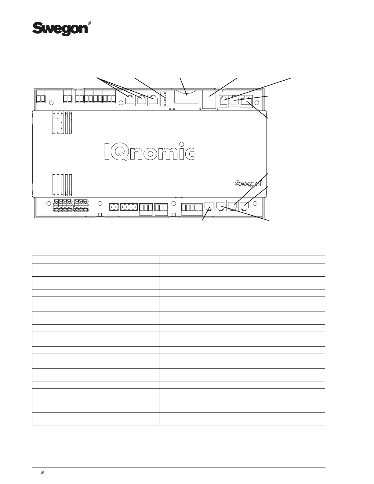
GB.GOLDLP.170830
56 www.swegon.com
We reserve the right to alter specifications without notice.
20.2.2 Connection to Terminal Blocks
Terminal Function Remarks
1,2 Output 1 Select function individually. Independent contact, max. 5 A/AC1, 1A/AC3, 250 V
AC.
3,4 Output 2 Select function individually. Independent contact, max. 5 A/AC1, 1A/AC3, 250 V
AC.
5,6 Input 1 Select function individually.
7,8 Input 2 Select function individually.
9,10 Control voltage Control voltage: 24 V AC, max. permissible load : 28 VA. 9 (G), 10 (G0).
11,12,13 Connections for EIA 485 11 communication connection A/RT+, 12 communication connection B/RT–,
13 = GND/COM.
14,15,16, 17 Heat exchanger motor 14 Earth, 15 Red, 16 Yellow, 17 Black.
18,19,20 Rotation monitor sensor 18 Brown, 19 Blue, 20 Black.
21,22 Supply voltage, H EXCH control 36 V AC, in
23,24 Supply voltage, control unit 18 V AC, in
25,26 Supply voltage, outputs 24 V 24 V AC, in
27,28,29 Not used.
30,31,32 Damper actuator, air recirculation damper 30 (G0) Black 24 V AC(-), 31 (G) Red 24 V AC(+), 32 (NO) White 24 V AC out if
active.
33 Output, fixed power supply: 12 V DC out 12 V DC to GND. Max permissible load: 500 mA
34 PWM input for Clean Air Control VOC sensor
35 Measuring zero, GND
36 Output, fixed power supply: 10 V DC out 10 V DC to GND Max. permissible load: 20 mA.
37 Input, 0–10 V DC, for demand-controlled
control of the airflow or set point displacement
Air quality sensor
Digital inputs, terminals 5–8, are of extra-low voltage type. Analogue inputs, terminal 37 has an input impedance of 66 k.Ω.
DIL selector switches:
GOLD LP, right-hand version: DIL switch 6 must be set to the ON position, the other switches must be set to the OFF position.
GOLD LP, left-hand version: DIL switches 1 and 6 must be set to the ON position, the other switches must be set to the OFF position.
12 34 56 78 910111213
1415 16 17 1819 20
21 22 2324 25 26 2728 29 3031 32 33343536 37
ON
DIL selector switch
External sensor and
IQnomic Plus modules
Memory card for logging and upgrading
Network connection Temperature sensor, supply air
Communication,
hand-held micro
terminal
Controller, air heater
Pressure sensor, extract
air fan*
Pressure sensor, supply
air fan*
Temperature sensor,
extract air*
Temperature sensor,
outdoor air*
* The designations apply to the right-hand version. In the left-hand version, the sensors change function and designation (the components are
named according to whether they are for supply air or extract air).
Page 57

GB.GOLDLP.170830
www.swegon.com 57
We reserve the right to alter specifications without notice.
20.3 Electrical Data
20.3.1 Air Handling Unit
MIN. POWER SUPPLY
Size 05:
1-phase, 3-wire, 230 V -10/+15%, 50/60 Hz, 10 AT
Size 08:
3-phase, 5-wire, 400 V -10/+15%, 50/60 Hz, 10 AT
20.3.2 Fans
RATED DATA PER FAN
Size 05: 1 x 230 V, 50/60 Hz, 0.74 kW.
Size 08: 3 x 400 V, 50/60 Hz, 1.0 kW.
20.3.3 Electrical equipment cubicle
One 2-pole 3A Automatic circuit breaker for 230V control
current
20.3.4 Heat Exchanger Motor
Step motor, 3-phase, 5.8 A (2A)*, 50 V max 90 V.
*) The motor controls limit the output power to the value specified.
20.3.5 Control Inaccuracy
Temperature ± 1oC.
Airflow ± 5%.
Page 58

GB.GOLDLP.170830
58 www.swegon.com
We reserve the right to alter specifications without notice.
21 ANNEXES
21.1 Compliancy Declaration
EC DECLARATION OF CONFORMITY FOR THE MACHINERY
Original
Directive 2006/42/EC
Swegon AB
Box 300
S-535 23 Kvänum, Sweden
declare under our own sole responsibility that
Air handling units with the following designation:
GOLD RX, GOLD PX, GOLD CX, GOLD LP, GOLD SD
and any accessories to the respective designation covered by these directives
comply with the Machinery Directive 2006/42/EC
and also to the following directives
2004/108/EG EMC, (Electromagnetic Compatibility Directive)
2006/95/EG LVD, (Low voltage directive)
The following harmonised standards have been applied:
EN ISO 12100:2010 (Machinery safety – General principle for design – Risk assessment
and risk reduction)
EN ISO 13857:2008 (Safety of Machinery -, Safety distances from machinery to prevent
hazard zones being reached by upper and lower limbs)
EN 60204-1 (Safety of machinery – Electrical equipment of machines)
EN 61000-6-2, -3 (Electromagnetic compatibility)
EN 61800-3 (Adjustable speed electrical power drive systems)
The following other standards and specifications have been applied:
EN 1886:2007 (Ventilation for buildings, air handling units – Mechanical performance)
EN 13053:2006 (Ventilation for buildings, air handling units - Rating and performance for
units, components and sections)
Person authorised to compile the technical documentation:
Dan Örtengren
Box 300
SE-535 23 Kvänum, Sweden
This declaration is applicable only if the air handling unit(s) has/have been installed
according to Swegon’s instructions and provided that the air handling unit(s) has/have not
been modified in any way.
Kvänum, 01/28/2011
Thord Gustafsson, Quality and Environmental Manager, Swegon AB
Annex II 1A
(Great Britain)
Page 59

GB.GOLDLP.170830
www.swegon.com 59
We reserve the right to alter specifications without notice.
21.2 Commissioning Record
Company
Our reference
Client Date SO No.
Plant Project/Air handling unit Subject No.
Plant address Type/Size Program version:
Filter calibration done
Time sw. clock, current time set
Other controls
Settings – time channels (scheduling), time switch clock
Channel Operating mode Times Week day
1 Low High : – : :
2 Low High : – : :
3 Low High : – : :
4 Low High : – : :
5 Low High : – : :
6 Low High : – : :
7 Low High : – : :
8 Low High : – : :
Settings – year channel (scheduling), time switch clock
Channel Operating mode Times Period
1 Inactive Stop High Low
: – : / – – / –
2 Inactive Stop High Low
: – : / – – / –
3 Inactive Stop High Low
: – : / – – / –
4 Inactive Stop High Low
: – : / – – / –
5 Inactive Stop High Low
: – : / – – / –
6 Inactive Stop High Low
: – : / – – / –
7 Inactive Stop High Low
: – : / – – / –
8 Inactive Stop High Low
: – : / – – / –
Page 60

GB.GOLDLP.170830
60 www.swegon.com
We reserve the right to alter specifications without notice.
Function Factory-preset value Adjusted value
Temperature
Temp. Reg. (Control) function X ERS 1 ERS 2 SA EA ERS 1 ERS 2 SA EA
Difference SA/EA (°C) 3,0
Step 2
Breakpoint (°C) 22,0
X1 15,0
Y1 20.0
X2 20.0
Y2 18.0
X3 22.0
Y3 14.0
Setpoint (°C) 21.5 21.5
Min. SA temp. (°C) 15.0
Min. SA temp. (°C) 28.0
Outdoor temp. compensation
X Inactive Active Inactive Active
Temperature
Winter comp. Y1 (°C) 3.0
End point, winter X1 (°C) -20.0
Starting point, winter X2 (°C) 10.0
Startpoint summer X3 (°C) 25.0
Endpoint summer X4 (°C) 40.0
Summer comp. Y2 (°C) 2.0
Summer night cooling
X Inactive Active Inactive Active
EA temp. start (°C) 22.0
EA temp. stop (°C) 16.0
Outdoor air temp. stop (°C) 10.0
SA Setpoint (°C) 10.0
In-oper. time start (hh:mm) 23:00
In-oper. stop (hh:mm) 06:00
Intermittent night-time heating
X Inactive Active Inactive Active
EA/Room start (°C) 16.0
EA/Room stop (°C) 18.0
SA Night setpoint (°C) 28.0
SA flow (m²/s / Pa)
2)
SA flow (m²/s / Pa) 0.0
Damper output =0
Morning BOOST
Time (hh:mm) 00:00
Damper
X Inactive Active Inactive Active
EA fan
X Inactive Active Inactive Active
EA/Room temp 22.0°C
EA min 15.0°C
SA max 28.0°C
Set point displacement
X Inactive Active Inactive Active
External sensor
External EA/Room
X Inactive IQnom Comm. Inactive IQnom Comm.
External outdoor
X Inactive IQnom Comm. Inactive IQnom Comm.
Page 61

GB.GOLDLP.170830
www.swegon.com 61
We reserve the right to alter specifications without notice.
Function Factory-preset value Adjusted value
Flow/pressure
Fan Regulation, SA* X Flow Pressure Need Slave Flow Pressure Need Slave
Fan Regulation, EA* X Flow Pressure Need Slave Flow Pressure Need Slave
Flow, low speed* SA
1) 1)
EA
1) 1)
Flow, high speed* SA
2) 2)
EA
2) 2)
Flow, max speed SA
4) 3) 4)
EA
4) 3) 4)
Flow, min. speed SA
5)
EA
5)
Pressure, low speed* SA (Pa) 100
EA (Pa) 100
Pressure, high speed* SA (Pa) 200
EA (Pa) 200
Max. fan speed* SA (%) 100%
EA (%) 100%
Pressure, max speed * SA (Pa) 400
4)
EA (Pa) 400 4)
Demand-contr., low speed SA (%) 25
EA (%) 25
Demand-contr., high speed SA (%) 50
EA (%) 50
Clean Air Control
X Inactive Active Inactive Active
VOC sensor
Analogue X Bus Analogue Bus
VOC low speed % 50
VOC high speed % 30
Min. flow m
3
/s 0.08 (size 05) or 0.2 (size 08)
Max. flow m
3
/s 0.53 (size 05) or 0.74 (size 08)
Outdoor temp. compen.
X Inactive Active Inactive Active
Flow
Winter compens. Y1 (%) 30
End point, winter X1 (°C) -20
Start. point, winter X2 (°C) 10
Down-speed regulation
Function
Inactive X SA SA + EA Inactive SA SA + EA
Neutral zone (°C) 0,0
In-operation
Time switch clock function X 1. Low – high 2. Stop – low – high 1. Low – high 2. Stop - low - high
Slave control
C-Factor 1,0
Filter function Inact. SA EA X SA+EA Inact. SA EA SA+EA
Prefilter X Inact. SA EA SA+EA Inact. SA EA SA+EA
Extended operation
External low speed (h:mm) 0:00
External low speed (h:mm) 0:00
* Not used for Clean Air Control
Page 62
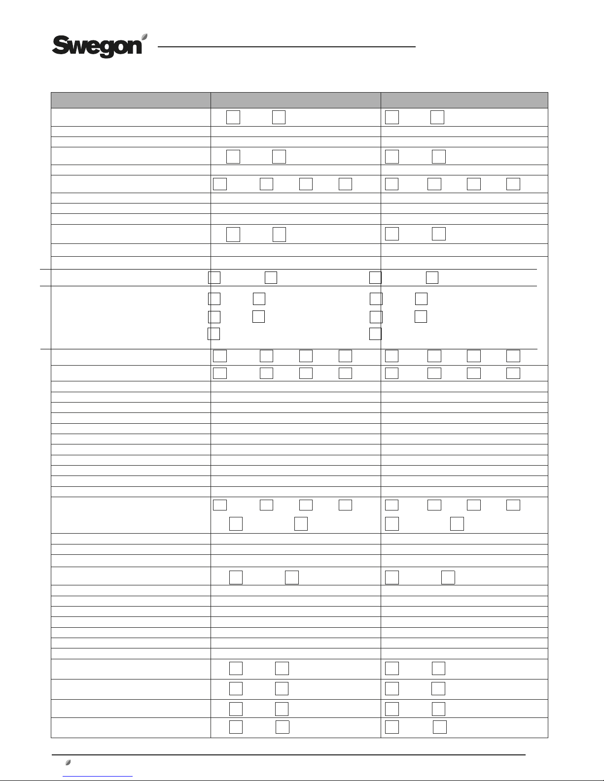
GB.GOLDLP.170830
62 www.swegon.com
We reserve the right to alter specifications without notice.
Function Factory-preset value Adjusted value
Summer/winter time
Inactive X Active Inactive Active
Heating
Heat exchanger
Defrosting
X Inactive Active Inactive Active
Reheating
Exercising X Inact. Pump Valve P+V Inact. Pump Valve P+V
Exercise period 3 Min.
Interval 24 hrs.
"Heating BOOST"
Function, Off/On
X Inactive Active Inactive Active
Start limit, SA temp. (°C) 3,0
Ramp time (%) 2.5
Exercising Cooling relay 1 X Inactive Pump P+V Valve Inactive Pump P+V Valve
Cooling relay 2 X Inactive Pump P+V Valve Inactive Pump P+V Valve
Exercise period 3 Min.
Interval 24 hrs.
Control reaction speed
Step duration (s) 300
Outdoor temp. limit Step 1 (°C) 3,0
Step 2 (°C) 5,0
Step 3 (°C) 7,0
Reset time (s) 480
Cool. min. SA flow (m³s) 0,1
Cool. min. EA flow (m³s) 0,1
Neutral zone (°C) 2,0
"Cooling BOOST" X Inactive Comf. Econ. Sequ. Inactive Comf. Econ. Sequ.
Comf.+econ. Econ.+sequ. Comf.+econ. Econ.+sequ.
Start limit SA temp. (°C) 3,0
Ramp time (%) 2,5
Humidity
Dehumidification control
X Inactive Active Inactive Active
Rel. hum., SA (%RH 50%
Inputs/Outputs
Relay 1 A Alarm output 6)
Relay 2 B Alarm output 6)
Input 1 External low speed 7)
Input 2 External high speed 7)
"IQnomic Plus"
I/O Module No. 0 Input/Output
connections
X Inactive Active Inactive Active
I/O Module No. 3 Ext. monitoring
X Inactive Active Inactive Active
I/O Module No. 6 Ext. cooling
X Inactive Active Inactive Active
I/O Module No. 9 Preheating
X Inactive Active Inactive Active
Cooling
Cooling unit controls
Stepless
0-10 V
Stepless
10-0 V
On/off
1-step
On/off
2-step
On/off
3-step binary mode
Inactive Auto
operation
Inactive Auto
operation
X
X
Stepless
0-10 V
Stepless
10-0 V
On/off
1-step
On/off
2-step
On/off
3-step binary mode
Page 63
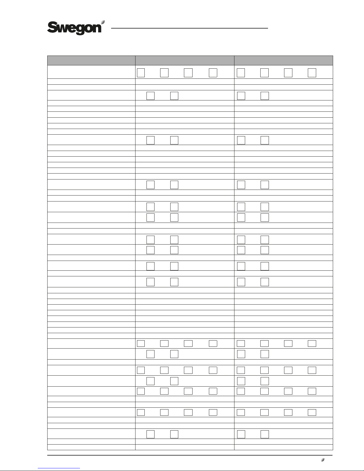
GB.GOLDLP.170830
www.swegon.com 63
We reserve the right to alter specifications without notice.
Function Factory preset value Adjusted value
All Year Comfort X Inact. Cool. Heat. C+H Inact. Cool. Heat. C+H
Heating water temp. (°C) 30
Cooling water temp. (°C) 14
Outdoor comp., Heating water
X Inact. Active Inact. Active
Outdoor temp. (X1) (°C) -20
Heating water (Y1)(°C) 40
Outdoor temp. (X2)(°C) 5
Heating water (Y2)(°C) 30
Outdoor temp. (X3)(°C) 15
Heating water (Y3)(°C) 20
Outdoor comp., Cooling water
X Inact. Active Inact. Active
Outdoor temp. (X1) (°C) 10
Cooling water (Y1)(°C) 22
Outdoor temp. (X2)(°C) 20
Cooling water (Y2)(°C) 18
Outdoor temp. (X3)(°C) 25
Cooling water (Y3)(°C) 14
Room comp., Heating water
X Inact. Active Inact. Active
Room temperature (°C) 21
P-band (°C) 5
Night blocking
Inact. Active Inact. Active
Room comp., Cooling water
X Inact. Active Inact. Active
Room temperature (°C) 21
P-band (°C) 5
Night blocking
Inact. Active Inact. Active
Night comp., Heating water
X Inact. Active Inact. Active
Temp. comp. (°C) -2
Night comp., Cooling water
X Inact. Active Inact. Active
Temp. comp. (°C) 2
Night comp.
X Inact. Active Inact. Active
Channel 1, Start, Stop, Weekday Inactive
Channel 2, Start, Stop, Weekday Inactive
Pump operation, Heating water
Outdoor temp. Start (°C) 15
Outdoor temp. Stop (°C) 18
Pump operation, Cooling water
Outdoor temp. Start (°C) -20
Outdoor temp. Stop (°C) -25
Alarm function, Heating water
Pump alarm X Inact. Open Close Cont. Inact. Open Close Cont.
Valve
X Inact. Active Inact. Active
Alarm function, Cooling water
Pump alarm X Inact. Open Close Cont. Inact. Open Close Cont.
Valve
X Inact. Active Inact. Active
Exercising, Heating water X Inact. Pump P+V Valve Inact. Pump P+V Valve
Exercising period, (min) 3
Interval (h) 24
Exercising, Cooling water X Inact. Pump P+V Valvev Inact. Pump P+V Valve
Exercising period, (min) 3
Interval (h) 24
Dew point comp.
X Inact. Active Inact. Active
Neutral zone (°C) 2
Comp. air flow (%) 10
Page 64

GB.GOLDLP.170830
64 www.swegon.com
We reserve the right to alter specifications without notice.
Function Factory preset value Adjusted value
OPTIMIZE
X Inactive Active Inactive Active
Upper damper limit (%) 90
Lower damper limit (%) 70
Step size (Pa) 20
Interval (min) 2
Permissible deviation (Pa) 10
Power up start delay (min) 15
Min. pressure (Pa) 50
Max. pressure (Pa) 400
"IQnomic Plus"
I/O module Nr 0 Input/Output
X Inactive Active Inactive Active
I/O module Nr 3 Ext. monitoring
X Inactive Active Inactive Active
If active, function:
I/O module Nr 6 Ext. cooling
X Inactive Active Inactive Active
I/O module Nr 7 All Year Comfort
X Inactive Active Inactive Active
I/O module Nr 8 Booster air
diffusers
X Inactive Active Inactive Active
I/O module Nr 9 Preheating
X Inactive Active Inactive Active
I/O module Nr A Heating zone
X Inactive Active Inactive Active
I/O module Nr B
Cooling zone
X Inactive Active Inactive Active
Page 65

GB.GOLDLP.170830
www.swegon.com 65
We reserve the right to alter specifications without notice.
Function Factory-preset value Adjusted value
Alarm setting
Fire alarm function
Internal fire alarms
X Inactive Active Inactive Active
External fire alarm Alarm resetting
X Man. Auto Man. Auto
Fan oper. in the event of a fire X Inactive SA EA SA+EA Inactive SA EA SA+EA
SA fan speed in event of fire (%) 100
EA fan speed in event of fire (%) 100
External alarms
Time delay Alarm 1 (s) 10
Alarm on closure, Alarm 1 1
Alarm reset
X Man. Auto Man. Auto
Time delay Alarm 2 (s) 10
Alarm on closure, Alarm 2 1
Alarm reset
X Man. Auto Man. Auto
Alarm limit temperature
Deviation, SA setpoint 5,0
Min. EA temperature 15,0
Filter function
Filter alarm limit
SA (%/Pa) 10/100
EA (%/Pa) 10/100
H EXCH defrosting
Alarm limit (Pa) 50
Service period
Alarm limit (month) 12
Alarm priority See the following pages -
Hand-held micro terminal settings
Language English
Flow unit
l/s X m3/s m3/h l/s m3/s m3/h
Min./max. setting
Setpoint, SA/EA (°C) 15,0/40,0
Min. limit, SA (°C) 13,0/18,0
Max. limit, SA (°C) 25,0/45,0
Break point, ERS Regulation (°C) 15,0/23,0
SA/EA Difference (°C) 1,0/5,0
Initial setting –
Communication
EIA-485
Protocol Modbus RTU
Address 1
PLA (Exoline) 1
ELA (Exoline) 1
Speed 9600
Parity None
Stop bit 1
Page 66

GB.GOLDLP.170830
66 www.swegon.com
We reserve the right to alter specifications without notice.
Function Factory-preset value Adjusted value
Ethernet
Mac Id Individual
DHCP server Inactive
IP address 10.200.1.1
Port no. 80
Net mask 255.0.0.0
GateWay 000.000.000.000
DNS server
No. 1 000.000.000.000
No. 2 000.000.000.000
Modbus TCP
IP 000.000.000.000
Port no. 502
Net mask 000.000.000.000
BACNet IP
Function Inactive
Device ID 0000000
Port nr. 47808
The values by turns refer to sizes 05 and 08.
1) 0.2, 03 m
3
/s.
2) 0.3, 0.4 m3/s.
3) 0.53, 0.74 m3/s.
4) Only in combination with Cooling BOOST. 0.53, 0.74 m3/s.
5) Only in combination with Demand control. 0.08, 0.20 m3/s.
6) Possible options: Control of outdoor air/exhaust air damper, in-operation indication, low speed operation indication, indication or
high speed operation, group alarm A, group alarm B, control of external heating, control of external cooling.
7) Possible options: External stop, external low speed operation, external high speed operation, external alarm 1, external alarm 2,
external reset, external heating, external fire alarm.
Page 67

GB.GOLDLP.170830
www.swegon.com 67
We reserve the right to alter specifications without notice.
Alarm No.:
Function
Factory preset value Adjusted value
Priority Indication Effect Priority Indication Effect
0=blocked LED 0=Operat. 0=blockedt LED 0=Operat.
A=A alarm 0=Off 1=Stop A=A alarm 0=Off 1=Stop
B=B alarm 1=On B=B alarm 1=On
1 External fire alarm tripped A**** 1 1*
2 Internal fire alarm tripped A**** 1 1*
3 Frost protection below alarm limit A**** 1 1*
4 R.hx. speed monitor tripped A 1 0**
5 Frost protection sensor defective A**** 1 1*
6 Supply air temp sensor defective A 1 1
7 Extract air temp sensor defective A 1 1
8 Outdoor air temp sensor defective B 1 0
9 No communication to r.hx. controller A *** 1 1
10 No communication to SA frequency conv. A *** 1 1
11 No communication to EA frequency conv. A *** 1 1
12 Over current in SA frequency conv. A *** 1 1
13 Over current in EA frequency conv. A *** 1 1
14 Under voltage in SA frequency conv. A *** 1 1
15 Under voltage in EA frequency conv. A *** 1 1
18 Excess temperature in SA frequency inverter A*** 1 1
19 Excess temperature in EA frequency inverter A*** 1 1
20 No communication SA frequency range
gateway A*** 1 1
21 No communication EA frequency range
gateway A*** 1 1
22 Hall sensor defective SA frequency range A*** 1 1
23 Hall sensor defective EA frequency range A*** 1 1
24 SA frequency range blocked A*** 1 1
25 EA frequency range blocked A*** 1 1
26 Start-up failure SA frequency range A*** 1 1
27 Over voltage in EA-2 frequency conv. A *** 1 1
30 Ext. EA/room temp sensor defective A *** 1 1
31 Ext. outdoor temp sensor defective B *** 1 0
34 Over current in r.hx. controller A *** 1 1
35 Under voltage in r.hx. controller A *** 1 1
36 Over voltage in r.hx. controller A *** 1 1
37 Over temperature in r.hx. controller A *** 1 1
38 R.hx pressure drop above alarm limit B *** 1 0
39 El.heating coil tripped A *** 1 1
40 Extract air temp below alarm limit A *** 1 1
41 Supply air temp below setpoint A *** 1 1
42 Ext.alarm No.1 tripped A*** 1 1
Page 68
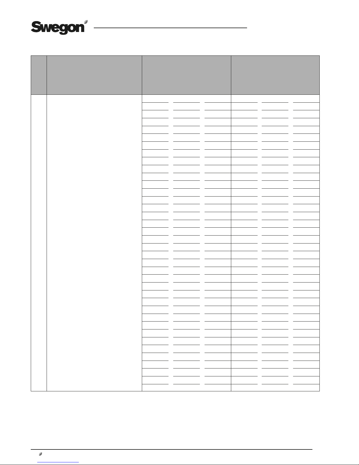
GB.GOLDLP.170830
68 www.swegon.com
We reserve the right to alter specifications without notice.
Alarm No.:
Function
Factory preset value Adjusted value
Priority Indication Effect Priority Indication Effect
0=blocked LED 0=Operat. 0=blockedt LED 0=Operat.
A=A alarm 0=Off 1=Stop A=A alarm 0=Off 1=Stop
B=B alarm 1=On B=B alarm 1=On
43 Ext. alarm No.2 tripped B *** 1 0
44 SA duct pressure below setpoint B *** 1 0
45 EA duct pressure below setpoint B *** 1 0
46 SA duct pressure above setpoint B *** 1 0
47 EA duct pressure above setpoint B *** 1 0
48 Supply airflow below setpoint B *** 1 0
49 Extract airflow below setpoint B *** 1 0
50 Supply airflow above setpoint B *** 1 0
51 Extract airflow above setpoint B *** 1 0
52 Supply air filter dirty B *** 1 0
53 Extract air filter dirty B *** 1 0
54 Service period past alarm limit B *** 1 0
55 No comm. SA air flow pressure sensor A *** 1 1
56 No comm. EA air flow pressure sensor A *** 1 1
57 No comm. SA filter pressure sensor B *** 1 0
58 No comm. EA filter pressure sensor B *** 1 0
59 No comm. SA duct pressure sensor A *** 1 1
60 No comm. EA duct pressure sensor A *** 1 1
61 No comm. r.hx. pressure sensor B *** 1 0
62 No communication to I/O-module No:0 B *** 1 0
63 No communication to I/O-module No:1 B *** 1 0
64 No communication to I/O-module No:2 B *** 1 0
65 No communication to I/O-module No:3 B *** 1 0
66 No communication to I/O-module No:4 B *** 1 0
67 No communication to I/O-module No:5 B *** 1 0
68 No communication to I/O-module No:6 B *** 1 0
69 No communication to I/O-module No:7 B *** 1 0
70 No communication to I/O-module No:8 B *** 1 0
71 No communication to I/O-module No:9 B *** 1 0
72 No communication to main controller I/O A 1 1
75 Supply air humidity sensor faulty A *** 1 1
76 Extract air humidity sensor faulty A *** 1 1
83 Supply air, prefilter fouled. B*** 1 0
84 Exhaust air prefilter, fouled B*** 1 0
85 Cooling Output 1 tripped A 1 0
86 Cooling Output 2 tripped A 1 0
89 No comm. with press. sensor by SA prefilter B*** 1 0
Page 69
GB.GOLDLP.170830
www.swegon.com 69
We reserve the right to alter specifications without notice.
Alarm No.:
Function
Factory preset value Adjusted value
Priority Indication Effect Priority Indication Effect
0=blocked LED 0=Operat. 0=blockedt LED 0=Operat.
A=A alarm 0=Off 1=Stop A=A alarm 0=Off 1=Stop
B=B alarm 1=On B=B alarm 1=On
90 No comm. with press. sensor by EA prefilter B*** 1 0
91 Frost prot. for preheating, below alarm limit A 1 1
92 Frost prot. for preheating sensor, faulty A 1 1
93 Preheating sensor faulty A 1 1
94 Electric air heater for preheating, tripped A*** 1 1
95 Preheating below setpoint A*** 1 1
96 Lost settings A 1 1
99 Time lock tripped A 1 1
102 Cooling valve I/O-7 defective B*** 1 0
103 Heating valve I/O-7 defective A*** 1 0
104 Cool. circuit pump I/O-7 tripped B*** 1 0
105 Heat. circuit pump I/O-7 tripped A*** 1 1
106 Cooling water temp. I/O-7 below set point B*** 1 0
107 Heat. water temp. l I/O-7 below set point A*** 1 0
108 Cooling water temp. I/O-7 above set point 0*** 1 0
109 Heating water temp. I/O-7 above set point 0*** 1 0
110 Cooling water temp. sensor I/0-7 defective B 1 0
111 Heating water temp. sensor I/0-7 defective A 1 0
143 No communication - OPTIMIZE B*** 1 0
160 No communication VOC sensor B 1 0
161 Internal comm. error VOC sensor B 1 0
162 Internal error VOC sensor B 1 0
163 VOC level below/over alarm limit B 1 0
* Not adjustable, always stops the air handling unit
** Not adjustable, stops the air handling unit at temperature below +5 °C
*** Blocked if the hand terminal does not display the main menu.
**** Cannot be blocked.
Adjustments carried out by:
Date
Company
Name
Page 70

GB.GOLDLP.170830
70 www.swegon.com
We reserve the right to alter specifications without notice.
21.3 Ecodesign data
Air Handling Units (including GOLD-E), EU regulation 327/2011 fan data, Technical documentation data
Datum: 2013-09-19
Impel ler
diamet er
Motor power
Power
input P
ed
Air Flow
q
v
Pressure
increase p
fs
Speed n
mm
kW Actu al Req 2013 Req 2015 A ctual Req 2013 Req 2015 kW m³/s Pa minˉ¹
AHU data
Fan data
Data acc ording to Er P directi ve in techn ical docum entation an d free access w ebpage
Type Size
Impel ler
type
Motor
manufacture
Specific
ratio
Overall ef ficiency η
e(s) Efficienc y grade N
Efficiency
category
Vaiable
speed
drive
Instal lation
category
Air Handling Units (including GOLD-E), EU regulation 327/2011 fan data, Technical documentation data
Datum: 2013-09-19
Impel ler
diamet er
Motor power
Power
input P
ed
Air Flow
q
v
Pressure
increase p
fs
Speed n
mm
kW Actu al Req 2013 Req 2015 A ctual Req 2013 Req 2015 kW m³/s Pa minˉ¹
02 ebm-papst 250 ebm-papst A Static Yes 1, 00 49,9 41,5 45,5 66,5 58 62 0,268 0,290 410 2690
03 ebm-papst 250 ebm-papst 0,38 A Static Yes 1,01 51,0 42,9 46,9 66,2 58 62 0,361 0,323 510 3000
05 Stål 250 ebm-papst 0,68 A Static Y es 1,01 59,3 45,7 49,7 71,6 58 62 0,670 0,435 830 3845
08 Aluminium 288 ebm-papst 0,9 A Static Y es 1,01 65,8 47,0 51,0 76,8 58 62 0,901 0,577 941 3415
AHU data
Fan data
Data acc ording to Er P directi ve in techn ical docum entation an d free access w ebpage
Type Size
Impel ler
type
Motor
manufacture
Specific
ratio
Overall ef ficiency η
e(s) Efficienc y grade N
Efficiency
category
Vaiable
speed
drive
COMPACT
Instal lation
category
GOLD
LP
Page 71

GB.GOLDLP.170830
www.swegon.com 71
We reserve the right to alter specifications without notice.
Available static pressure, Pa
Air flow, m
3
/s
The lower limit for the airflow when the unit is operating in the airflow
regulation mode.
Recommended range for the design working point.
Permissible operating range when the fan is controlled to operate at a lower speed.
If pressure regulation is used, the airflow can be regulated to zero, however this
presupposes a certain static pressure drop in the ducting (approx. 50 Pa).
Permissible operating range in accordance with regulation 1253/2014
Working point with the highest air flow shall be found within the permissible area. In
case of unbalanced air flows; mean working point, supply extract shall be used.
Working points with less air flow is allowed to be found outside the permissible range
e.g. in case of variable air flow.
Max. limit, Ecodesign 2016.
Outer limit - largest permissible air flow at maximum speed.
Remaining outer limits.
Recommended average working point.
Thermal
efficiency
Nominal
flow rate
Effective
electric
power
SFPint
Face
velocity
Nominal
external
pressure
Internal
pressure drop
vent. comp.
Overall fan
efficiency
(EU) No
327/2011
Maximum
external
leaking rate
Maximum
internal
leakage
Energy
performance
of filters
Casing
sound power
level, LwA
% m³/s kW W/(m³/s) m/s Pa Pa % % % kWh/year dB(A)
Red Min. - low NRVU, BVU variable speed Other 71 0,08 0,04 495 0,4 0 24 59,3 - - - 18
Red Min. - high NRVU, BVU variable speed Other 71 0,08 0,54 166 0,4 994 24 59,3 - - - 58
Yellow Average NRVU, BVU variable speed Other 81 0,34 0,42 647 1,6 300 148 59,3 - - - 48
Blue Max. - high NRVU, BVU variable speed Other 79 0,49 0,67 1244 2,4 241 255 59,3 5 1 2170 52
Red Max. - low NRVU, BVU variable speed Other 79 0,49 0,54 1463 2,4 0 255 59,3 - - - 52
Red Min. - low NRVU, BVU variable speed Other 71 0,08 0,04 491 0,4 0 24 59,3 - - - 17
Red Min. - high NRVU, BVU variable speed Other 71 0,08 0,54 164 0,4 994 24 59,3 - - - 58
Yellow Average NRVU, BVU variable speed Other 81 0,34 0,42 624 1,6 300 143 59,3 - - - 48
Blue Max. - high NRVU, BVU variable speed Other 79 0,50 0,67 1206 2,4 243 244 59,3 5 1 2200 52
Red Max. - low NRVU, BVU variable speed Other 79 0,50 0,53 1433 2,4 0 244 59,3 - - - 52
Red Min. - low NRVU, BVU variable speed Other 66 0,10 0,03 0 0,4 0 24 65,8 - - - 19
Red Min. - high NRVU, BVU variable speed Other 78 0,10 0,89 1248 2,5 211 277 65,8 - - - 55
Yellow Average NRVU, BVU variable speed Other 80 0,48 0,60 613 1,7 350 157 65,8 - - - 50
Blue Max. - high NRVU, BVU variable speed Other 78 0,72 0,89 1248 2,5 211 277 65,8 1 1 2930 55
Red Max. - low NRVU, BVU variable speed Other 78 0,72 0,73 1417 2,5 0 277 65,8 - - - 55
Red Min. - low NRVU, BVU variable speed Other 66 0,10 0,03 0 0,4 0 23 65,8 - - - 19
Red Min. - high NRVU, BVU variable speed Other 78 0,10 0,88 1142 2,6 220 246 65,8 - - - 55
Yellow Average NRVU, BVU variable speed Other 80 0,48 0,58 553 1,7 350 141 65,8 - - - 50
Blue Max. - high NRVU, BVU variable speed Other 78 0,73 0,88 1142 2,6 220 246 65,8 1 1 3090 55
Red Max. - low NRVU, BVU variable speed Other 78 0,73 0,71 1323 2,6 0 246 65,8 - - - 55
Working poin
t
Part of information requirements for NRVU according to Regulation (EU) No 1253/201
4
In and outlet
connections
Colour Remark
AHU
type
Type of
drive
Type of
HRS
Size
Duct
Full face
05
08
Duct
Full face
Page 72

GB.GOLDLP.170830
72 www.swegon.com
We reserve the right to alter specifications without notice.
All documentation is available in digital form and can be downloaded from
www.swegon.com
 Loading...