

Swegon GOLD RX Series, GOLD RX 120, GOLD RX 100, GOLD CX Series, GOLD CX 100 Instructions For Installation Manual
...Page 1
GB.GOLDINE120.130915
Swegon reserves the right to alter specifications.
www.swegon.com 1
Instructions for Installation
GOLD RX/CX, sizes 100/120
The document was originally written in Swedish.
Page 2

GB. GOLDINE120.130915
Swegon reserves the right to alter specifications.
2
www.swegon.com
1. Installation ............................................... 3
1.1 General .................................................................. 3
1.2 Transport within the site ......................................... 3
1.3 Parts packed together with the unit ........................ 3
1.3.1 Hand-held micro terminal .................................. 3
1.3.2 Supply air sensor ............................................... 3
1.3.3 Document pocket ............................................. 3
1.4 Location ................................................................. 3
1.5 Method of delivery ................................................. 3
1.5.1 GOLD RX .......................................................... 3
1.5.2 GOLD CX .......................................................... 3
1.6 Lifting .................................................................... 4
1.6.1 With a fork-lift truck ......................................... 4
1.6.2 With a crane ..................................................... 4
1.6.2.1 Complete units ............................................ 4
1.6.2.2 Heat exchanger section, supplied split into two
casing sections and rotor (GOLD RX only) ................. 5
1.7 To assemble the heat exchanger unit section,
if required (GOLD RX only) ........................................... 7
1.7.1 Alternative 1 ..................................................... 7
1.7.2 Alternative 2 ................................................... 11
1.7.3 Common for Alternatives 1 and 2 ................... 15
1.7.3.1 To adjust the rotor’s inclination ................... 15
1.7.3.2 Sealing plates/purging sector ...................... 16
1.7.3.3 Pressing roller ............................................. 16
1.7.3.4 Vinyl-coated fabric seal .............................. 16
1.7.3.5 Sealing ....................................................... 17
1.7.3.6 Decorative fittings ...................................... 18
1.8 Transport locking devices, fans ............................. 19
1.9 Version and fan arrangement ............................... 19
1.9.1 GOLD RX ........................................................ 19
1.9.2 GOLD CX ........................................................ 19
1.10 The docking of unit sections ............................... 20
1.10.1 Fan/filter sections .......................................... 20
1.10.2 Fixation, front of the unit .............................. 20
1.10.3 Fixation, rear of the unit ................................ 21
1.10.4 Decorative fittings ......................................... 22
1.10.5 Electrical quick-fit connectors ........................ 23
1.10.6 To connect air tubes to filter pressure sensors 24
1.11 Duct connection ................................................. 25
1.12 To install the supply air sensor ............................. 25
1.13 Electrical connections, protective motor switch and
communication cables (GOLD CX only) ....................... 26
1.13.1 Protective motor switch ................................ 26
1.13.2 Communication cables ................................. 26
1.14 To connect the electric power supply .................. 27
1.15 To Connect external cables ................................. 28
1.15.1 GOLD RX ...................................................... 28
1.15.2 GOLD CX ...................................................... 28
1.16 Installation of pipework package
(GOLD CX only) .......................................................... 29
2. Dimensions ............................................29
2.1 GOLD RX 100/120 ............................................... 29
2.2 GOLD CX 100/120 ............................................... 30
3. Explanation – wiring terminals,
control unit ................................................ 31
Content
Page 3
GB.GOLDINE120.130915
Swegon reserves the right to alter specifications.
www.swegon.com 3
3440
1070
1070
1868
1170 2350
1861
2930
1.1 General
All staff concerned must acquaint themselves with these
instructions before beginning any work on the unit. Any
damages to the unit or parts of it due to improper handling or misuse by the purchaser or the fitter cannot be
considered subject to guarantee if these instructions have
not been followed correctly.
The product identification plates are located on the
inspection side of the air handling unit and inside the
electric equipment cubicle of the unit. Refer to the particulars on the product identification plate when you contact
Swegon.
The air handling unit is supplied in packaged condition.
Possible ordered accessories are supplied in separate pack-
aging with the unit.
Remove the air handling unit’s protective plastic foil pack-
aging when you have completed the installation.
1.2 Transport within the site
Before removing the transport pallet/transport cradle, if
used, determine whether a forklift truck or a pallet transporter will be used for further transporting the unit within
the site to the spot where it will be installed.
1.3 Parts packed together with the unit
Individually packaged components such as the hand-held
micro terminal, decorative fittings, commissioning plates,
bolts, supply air sensor and document pocket are inside
the air handling unit when it is delivered.
1.3.1 Hand-held micro terminal
The hand-held micro terminal is equipped a 3 m long
cable and a quick-fit connector. For particulars of the electrical connections, see 1.15. A holder for wall-mounting
is supplied with the hand-held micro terminal. The holder
can be secured to the outside of the air handling unit
(does not apply to the outdoor units) or another appropriate place. An extension cable (8 metres long) is available
as an accessory.
1.3.2 Supply air sensor
The sensor is equipped with a 10 m long cable and a
quick-fit connector. For particulars regarding installation,
see 1.12. For particulars of the electrical connections, see
1.15.
1.3.3 Document pocket
Secure the document pocket to the exterior of the air
handling unit or another appropriate place.
1.4 Location
The air handling unit must be mounted horizontally on a
flat and firm supporting surface and this surface must be
constructed in a way enabling it to support the weight of
the unit.
1. Installation
When installing the air handling unit and connecting pipework and electric cables, make sure that adequate free
space is provided for opening the inspection doors and
covers and withdrawing functional sections, such as filter
cassettes and fan assemblies, clear of the unit casing.
Inspection space required
A clear space of 1,000 mm should be provided in front of
the unit for opening the inspection doors.
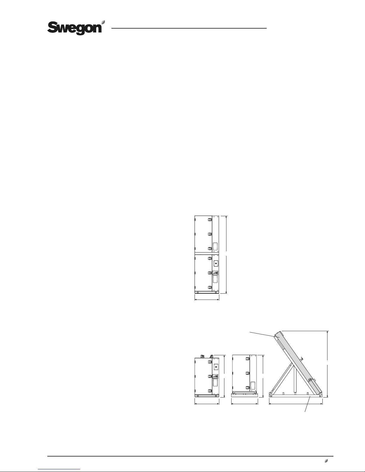
1.5 Method of delivery
1.5.1 GOLD RX
The GOLD RX 120 is normally supplied in five separate
sections: two fan sections, two filter sections and one
heat exchanger section.
The heat exchanger section can also be supplied split into
two casing sections and rotor, in which case the rotor is
supplied tilted in a transport cradle (transport height =
2,930 mm, minimum transport width = 2,350 mm). See
Section 1.7 for installation particulars.
For other dimensions and weights, see Section 2.1.
Heat exchanger section supplied as a separate unit
Heat exchanger section, supplied split
into two casing sections and rotor
Rotor, Ø 3150
Transport cradle
3440
1070
1.5.2 GOLD CX
The GOLD CX 120 is supplied as six separate units:
Two fan sections, two filter sections and two coil heat
exchanger sections.
For dimensions and weights, see Section 2.2.
Page 4
GB. GOLDINE120.130915
Swegon reserves the right to alter specifications.
4
www.swegon.com
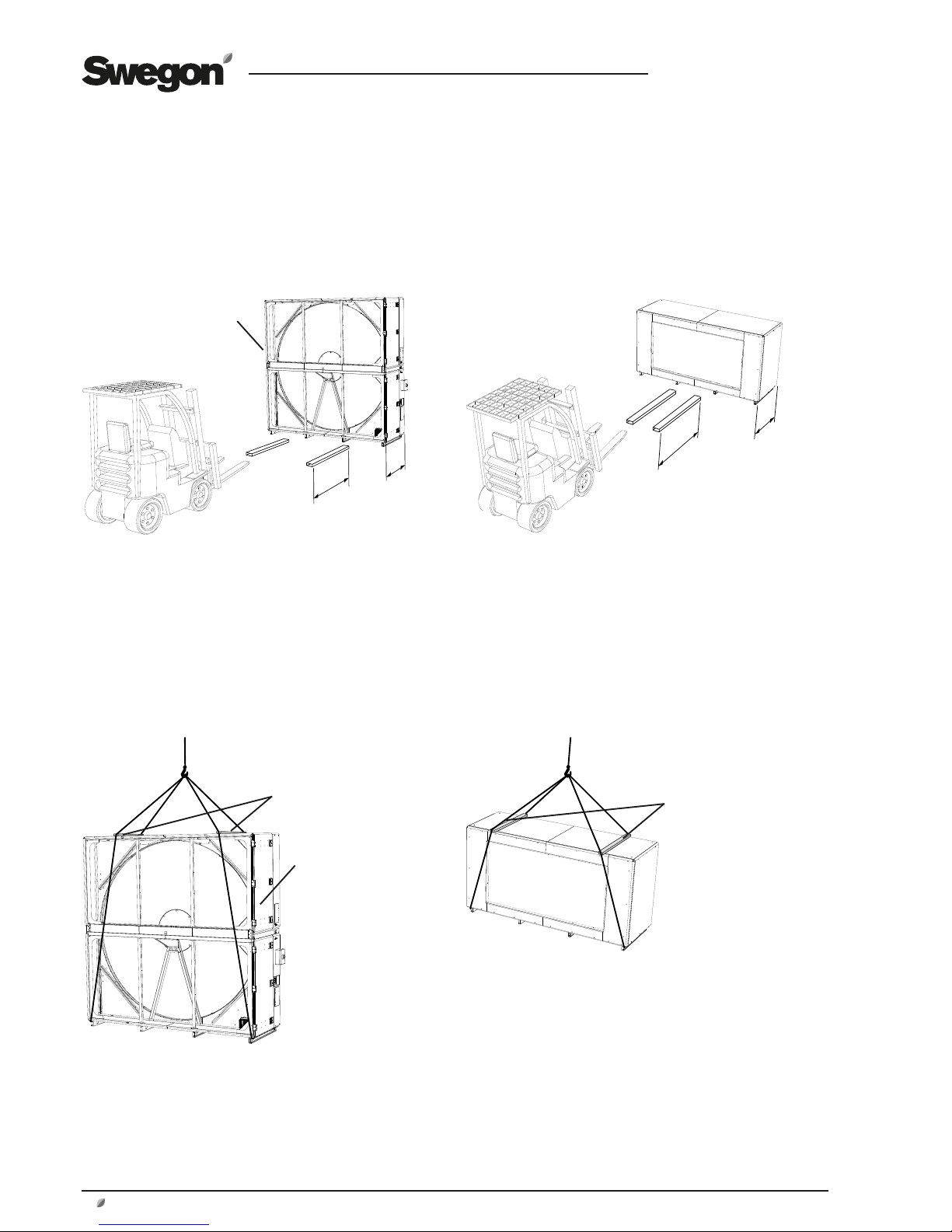
1.6 Lifting
1.6.1 With a fork-lift truck
L
L
NOTE! Make sure that
forks of the fork-lift truck
are sufficiently long!
Other sections
L
L
Rotary heat exchanger (GOLD RX only).
NOTE! Make sure that
forks of the fork-lift truck
are sufficiently long!
NOTE! High centre of gravity!
1.6.2 With a crane
1.6.2.1 Complete units
Other sections
NOTE! A line spreader must
be used!
NOTE! High centre of
gravity!
NOTE! A line spreader must
be used!
Rotary heat exchanger (GOLD RX only).
Page 5

GB.GOLDINE120.130915
Swegon reserves the right to alter specifications.
www.swegon.com 5
Lower casing section
NOTE! A line spreader must
be used!
Upper casing section
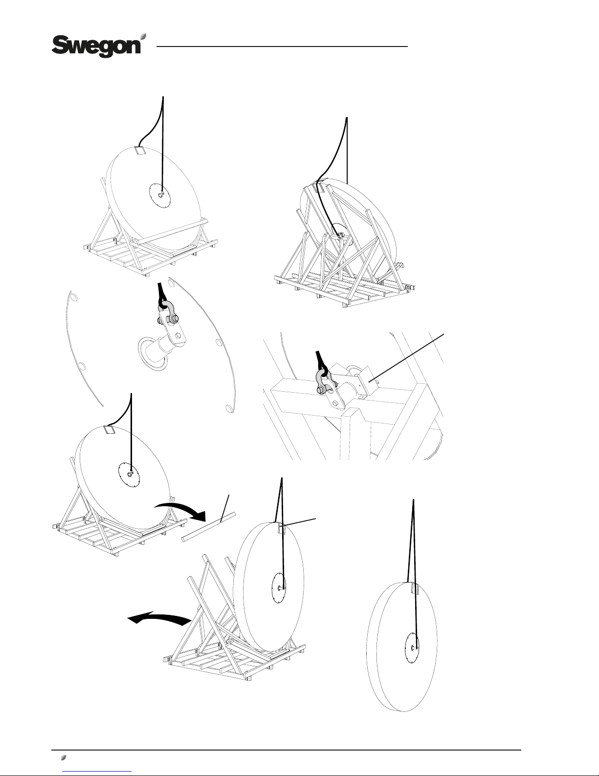
1.6.2.2 Heat exchanger section, supplied split into two casing sections and rotor (GOLD RX only)
Page 6
GB. GOLDINE120.130915
Swegon reserves the right to alter specifications.
6
www.swegon.com
Rotor
Remove the
wooden stud
NOTE! Carefully raise the rotor so that it
will not be damaged! Make sure that the
lifting device rests against the protecting
plate at the top edge.
Protecting plate
Remove the anchor
plate
Page 7
GB.GOLDINE120.130915
Swegon reserves the right to alter specifications.
www.swegon.com 7
1.7 To assemble the heat exchanger unit
section, if required (GOLD RX only)
If the heat exchanger unit section is supplied in parts, they
must be jointed together. This can be done in two ways:
Alternative 1 is appropriate for use if there is sufficient free
space upward since this alternative is simpler. If sufficient
space is not available, Alternative 2 should be used.
If the heat exchanger unit section is supplied as one unit,
go on to Section 1.8.
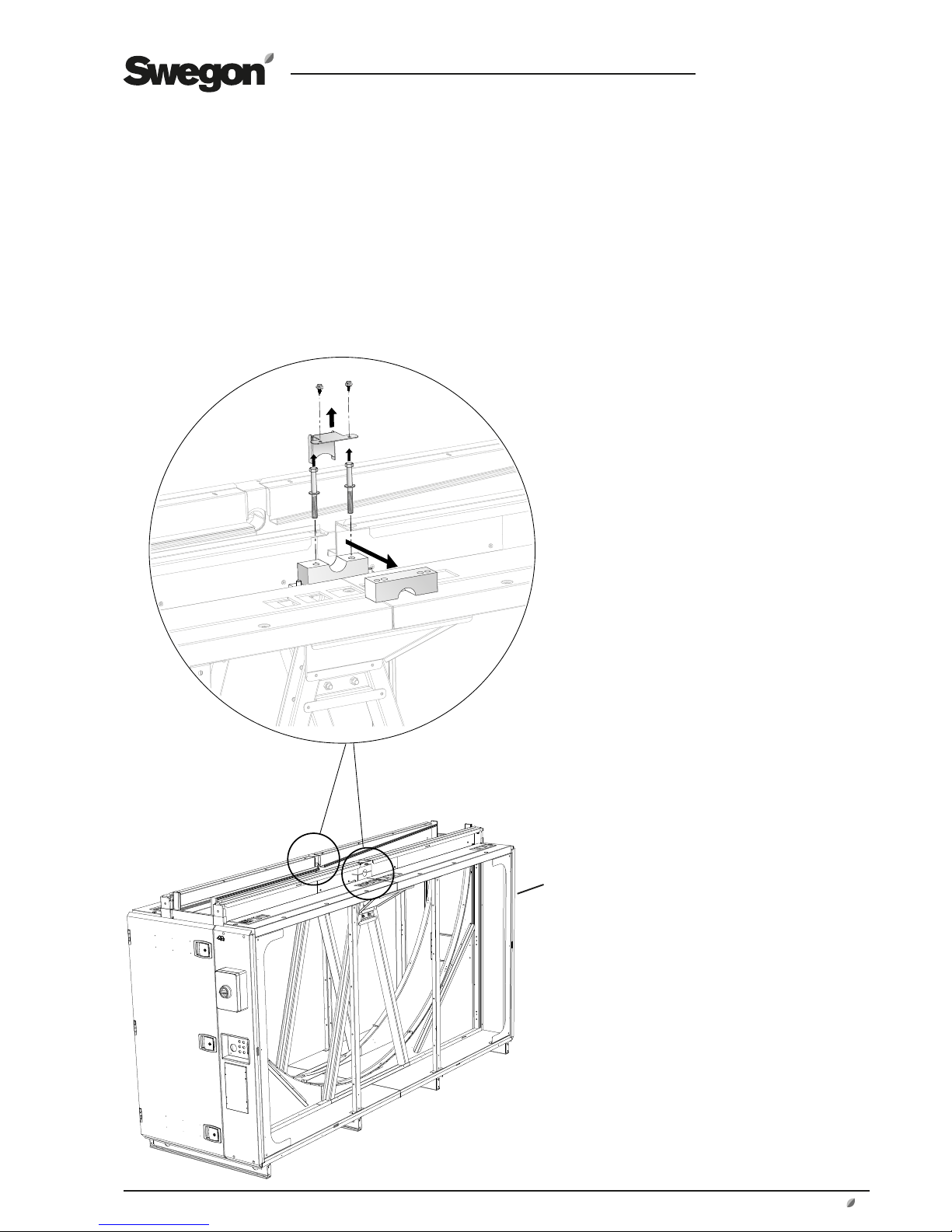
1.7.1 Alternative 1
Lower casing section
Shaft mounting brackets
Remove the upper shaft bracket and
the sealing plate (2x)
Page 8
GB. GOLDINE120.130915
Swegon reserves the right to alter specifications.
8
www.swegon.com
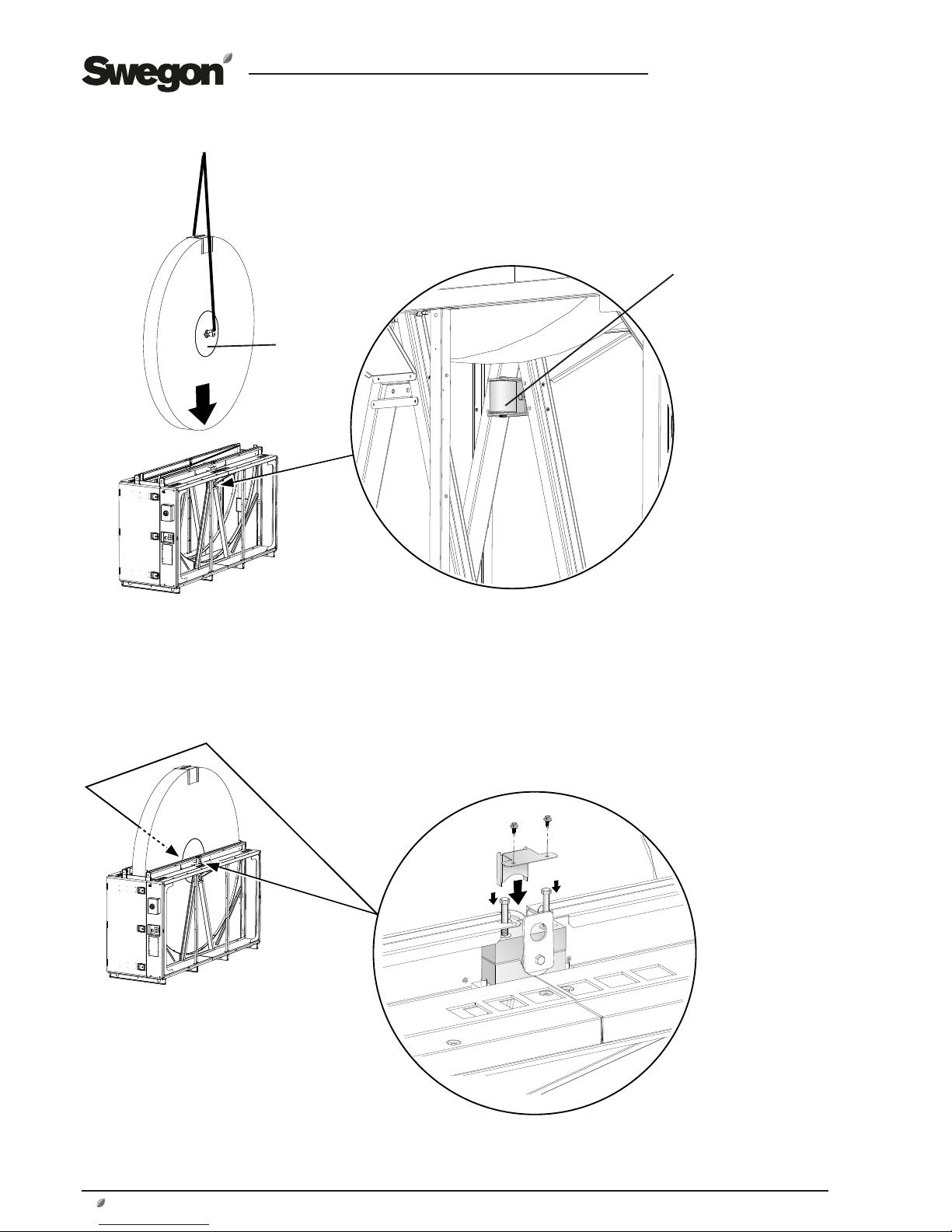
Lift the rotor into the lower casing section (see Section 1.6).
NOTE! IMPORTANT! The smooth side of the rotor hub (without holes) should face the pressing roller!
Be careful not to damage the rotor!
Hub side
Pressing roller
Mount the upper shaft bracket
and the sealing plate (2x)
Page 9
GB.GOLDINE120.130915
Swegon reserves the right to alter specifications.
www.swegon.com 9
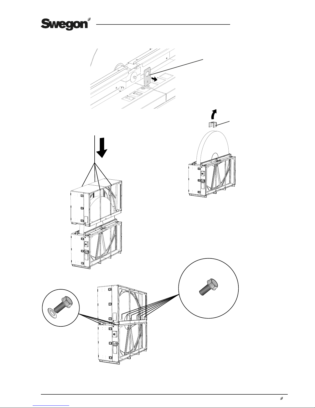
Remove the lifting lugs. Refit the bolts
and washers to the shaft end (2x).
Remove the protecting plate
of the rotor.
Lift the upper casing section
onto the lower casing section
(see Section 1.6).
2 x 6
Fix the upper casing section to the lower casing
section with the bolts supplied, screwing them
into the pre-fitted rivet nuts (a total of 20 pcs.).
2 x 4
Page 10
GB. GOLDINE120.130915
Swegon reserves the right to alter specifications.
10
www.swegon.com
Slacken off the two screws
holding the motor + mounting bracket. Move the motor +
mounting bracket back to their
original positions. Secure the
motor + mounting bracket with
bolts (6 bolts).
Unfasten the electrical equipment cubicle
and move it to the side.
Disconnect the electrical quick-fit connectors
from the fan motors and
the heat exchanger drive
motor.
NOTE! Do not disconnect
the cables from the electrical equipment cubicle
to the main switch.
Dismantle the heat exchanger motor + mounting bracket (6 bolts).
Move the motor + mounting bracket into position
shown in the illustration
and temporarily secure
them with two screws
Place the rotor drive belt
around the motor belt
pulley.
Reconnect the electrical quick-fit
connectors to the fan motors and
the heat exchanger drive motor.
Move the electrical equipment
cubicle back into position and
secure it with the appropriate
bolts.
See also Section 1.7.3 Common for Alternatives 1 and 2
Page 11

GB.GOLDINE120.130915
Swegon reserves the right to alter specifications.
www.swegon.com 11
1.7.2 Alternative 2
Unfasten the electrical equipment cubicle and move it to the
side. Disconnect the electrical quick-fit connectors from the fan
motors and the heat exchanger drive motor.
NOTE! Do not disconnect the cables from the electrical equipment cubicle to the main switch.
Dismantle the heat exchanger motor + mounting bracket
(6 bolts). Remove the sealing plate and tube.
Lower casing section
Shaft mounting brackets
Remove the upper shaft bracket
and the sealing plate (2x)
Page 12

GB. GOLDINE120.130915
Swegon reserves the right to alter specifications.
12
www.swegon.com
Lift the rotor from the side into the lower casing section (see
Section 1.6).
NOTE! IMPORTANT! The smooth side of the rotor hub (without holes) should face the pressing roller!
Be careful not to damage the rotor!
Hub side
Pressing roller
Mount the upper shaft bracket
and the sealing plate (2x)
Page 13

GB.GOLDINE120.130915
Swegon reserves the right to alter specifications.
www.swegon.com 13
Remove the lifting lugs. Refit the bolts
and washers to the shaft end (2x).
Remove the protecting plate of
the rotor.
Slacken off the two screws holding the motor + mounting
bracket. Move the motor + mounting bracket to the position
shown in the illustration. Secure the motor + mounting bracket
with bolts (6 bolts).
Move the motor + mounting bracket into position shown in the
illustration and temporarily secure them with two screws Place
the rotor drive belt around the motor belt pulley.
Reconnect the electrical quick-fit connectors to the fan motors
and the heat exchanger drive motor. Move the electrical equipment cubicle back into position and secure it with the appropriate bolts.
Fit the sealing plate
and tube.
Page 14

GB. GOLDINE120.130915
Swegon reserves the right to alter specifications.
14
www.swegon.com
Upper casing section
Remove the cover panel on the rear
side. Remove the sealing plates (2 pcs.).
Lift the upper casing section from the side onto the
lower casing section (see
Section 1.6).
Mount the cover panel and
the sealing plates (2 pcs.).
2 x 6
Fix the upper casing section to the lower casing
section with the bolts supplied, screwing them
into the pre-fitted rivet nuts (a total of 16 pcs.).
2 x 2
See also Section 1.7.3 Common for Alternatives 1 and 2
Page 15

GB.GOLDINE120.130915
Swegon reserves the right to alter specifications.
www.swegon.com 15
1.7.3 Common for Alternatives 1 and 2
1.7.3.1 To adjust the rotor’s inclination
L
L
≈ 0,5xL
≈ 0,5xL
The illustration shows an appropriate rotor inclination
setting for Fan Arrangement 1. The inclination must always be toward the filter, which means that the inclination for Fan Arrangement 2 is in the other direction.
The rotor’s inclination may need to be greater in applications that involve high airflows with associated high
pressure.
Slightly back off the locking bolts.
Do not dismantle the shaft bracket.
Adjust the inclination of the rotor by means
of the adjusting bolts. Tighten the adjusting
bolts equally.
When you have adjusted the inclination,
tighten the locking bolts.
Page 16

GB. GOLDINE120.130915
Swegon reserves the right to alter specifications.
16
www.swegon.com
1.7.3.2 Sealing plates/purging sector
Back off the screws
for the sealing plates/
purging sector. Arrange
the sealing plates/
purging sector so that
the bristles are against
the rotor. Tighten the
screws.
1.7.3.3 Pressing roller
Tension the pressing roller against the rotor hub until you no
longer can roll the pressing roller with your hand.
1.7.3.4 Vinyl-coated fabric seal
Slip the vinyl-coated fabric seal of the rotor (blue) over the rim
all the way around on both sides of the rotor.
Page 17

GB.GOLDINE120.130915
Swegon reserves the right to alter specifications.
www.swegon.com 17
1.7.3.5 Sealing
Apply appropriate sealing
compound/putty to corners
by the sealing plates/purging
sector (4 plates).
Apply appropriate sealing compound/
putty around the sealing plate of the
rotor shaft (2 plates).
Apply appropriate sealing compound/
putty to the joints between the upper casing section and the lower casing section
(front and rear).
Page 18

GB. GOLDINE120.130915
Swegon reserves the right to alter specifications.
18
www.swegon.com
1.7.3.6 Decorative fittings
Mount the decorative fittings with self-tap-
ping screws in the pre-punched holes.
Mount the decorative fittings with the pre-fitted M5
bolts in the pre-fitted rivet nuts.
Page 19

GB.GOLDINE120.130915
Swegon reserves the right to alter specifications.
www.swegon.com 19
Right-hand version
Left-hand version
Fan arrangement 1 Fan arrangement 2
Fan arrangement 1 Fan arrangement 2
1.9 Version and fan arrangement
1.9.1 GOLD RX
The GOLD RX 120 is supplied in the right-hand or a lefthand version and with fan arrangement 1 or 2, see the
illustration below.
For particulars of the delivery configuration and installation of the relevant air handling unit, see the decal on the
lower section of the heat exchanger.
Outdoor air Supply air Extract air Exhaust air
1.8 Transport locking devices, fans
The fans are equipped with transport locking devices (4x2
devices/fan, a total of 48 pcs.). All these must be removed,
see illustration.
1.9.2 GOLD CX
The GOLD CX 120 is supplied in the right-hand or a lefthand version and with fan arrangement 1, 2, 4 or 5, see
the illustrations below.
For particulars of the delivery configuration and installation of the relevant air handling unit, see the decal on the
lower section of the heat exchanger.
N.B.! Coil heat exchangers with control unit are always
located in the lower level. The supply air fan is marked 1;
the extract air fan is marked 2. These identifying decals are
affixed to the inner wall of the fan sections.
N.B.! If extract air flows through the lower level: The air
handling unit must be raised at least 50 mm (higher than
the upper edge of the base beams) to provide space for
the water trap. This can be done by mounting adjustable
feet (accessories, a minimum of 24 feet).
Right-hand version
Fan arrangement 1 Fan arrangement 2
Fan arrangement 5,
supply air upper
Fan arrangement 5,
supply air lower
Left-hand version
Fan arrangement 1 Fan arrangement 2
Fan arrangement 4,
supply air – upper level
Fan arrangement 4,
supply air - lower level
x 32, GOLD 100
x 48, GOLD 120
Page 20

GB. GOLDINE120.130915
Swegon reserves the right to alter specifications.
20
www.swegon.com
1.10 The docking of unit sections
Locate the fan/filter sections by the heat exchanger
section according to the delivery configuration (see
Section 1.9). Fix the fan/filter sections at thefront side
of the air handling unit to the heat exchanger section
with the bolts supplied, screwing them into the prefitted rivet nuts (a total of 2x4 pcs.).
The illustrations in Section 1.10 show a GOLD RX air handling unit with fan arrangement 2. The principle is however the same for the other air handling units.
1.10.1 Fan/filter sections
1.10.2 Fixation, front of the unit
Place the fan, filter and possible coil heat exchanger
sections on top of one another, according to the
delivery configuration (see Section 1.9). Fix the upper
section to the lower section with the bolts supplied,
screwing them into the pre-fitted rivet nuts (a total of
4 pcs.).
Page 21

GB.GOLDINE120.130915
Swegon reserves the right to alter specifications.
www.swegon.com 21
Alt. 1
External fixing.
Dismantle the blanking plate and insulation inside the
cover on the rear side of the air handling unit. Fix the
fan/filter sections to the heat exchanger section with
the bolts supplied, screwing them into the pre-fitted
rivet nuts (a total of 2x4 pcs.). Refit the blanking plate
and the insulation.
Securing with screws at the rear of the air handling unit
can be done in two ways, internally or externally. External
fixing (Alt. 1) is appropriate for use if there is sufficient free
space behind the air handling unit, since this alternative
is simpler. If sufficient space is not available, Alt. 2) can be
used.
Alt. 2
Internal installation.
Fix the fan/filter sections to the heat exchanger section
with the bolts supplied, screwing them into the prefitted rivet nuts (a total of 2x4 pcs.). The anchoring
points inside the unit are shown in the illustration.
In order to access the anchor points in the fan section,
you must unfasten the flexible connections and the
fan assemblies and move them outward toward the
inspection door. You can then tighten the screws from
the opening of the duct connection.
NOTE! You do not need to remove the fan assemblies
completely!
1.10.3 Fixation, rear of the unit
Blanking
plate
Page 22

GB. GOLDINE120.130915
Swegon reserves the right to alter specifications.
22
www.swegon.com
x2 (RX)
x3 (CX)
x2
x2
Press the decorative fittings firmly into the base
beam to engage them.
GOLD CX: Fit the decorative plate with cable
grommets on the heat exchanger section.
Joint together two decorative fittings with
screws as shown in the illustration. Then
secure the decorative fittings to the ends of
the base beams with screws.
Press the decorative against the base
beam to engage it firmly.
Joint together two decorative
fittings with screws as shown in
the illustration. Then secure the
decorative fittings to the ends
of the base beams with screws.
1.10.4 Decorative fittings
Page 23

GB.GOLDINE120.130915
Swegon reserves the right to alter specifications.
www.swegon.com 23
1A
2A
1A
2A
1B
1B
2B
GOLD 100
1A
2A
3A
1A
2A
3A
1B
2B
3B
1B
2B
3B
GOLD 120
2B
1A
2A
1A
2A
1B
1B
2B
GOLD 100
1A
2A
3A
1A
2A
3A
1B
2B
3B
1B
2B
3B
GOLD 120
2B
1.10.5 Electrical quick-fit connectors
Connect the electric cables with
quick-fit connectors between the
electrical equipment cubicle and
the fans.
The illustration shows the GOLD
RX, fan arrangement 2.
The principle is however the
same for the other air handling
units.
Cap. var. 1, 2
Cap. var. 2
Cap. var. 1, 2
Cap. var. 2
Cap. var. 1, 2
Cap. var. 2
Cap. var. 1, 2
Cap. var. 2
Page 24

GB. GOLDINE120.130915
Swegon reserves the right to alter specifications.
24
www.swegon.com
- +
Connect the air tube from the air nipple below the filter
to the + connection on the filter pressure sensor as
shown in the illustration. The air tubes are connected to
each air nipple (below the filter) and are rolled up inside
each fan/filter section.
The illustration shows the GOLD RX, fan arrangement 2.
The principle is however the same for other air handling
units.
1.10.6 To connect air tubes to filter pressure sensors
Page 25

GB.GOLDINE120.130915
Swegon reserves the right to alter specifications.
www.swegon.com 25
1.12 To install the supply air sensor
The supply air temp. sensor must be mounted inside the
supply air duct.
The sensor must be positioned at a spot that is at least 1.5
metres from the air handling unit.
NOTE! If an air heater and/or air cooler, if required, is
installed in the system, the sensor must be positioned 1.5
metres from the unit measured from this component.
1. Measure and mark where the sensor is to be placed.
2. Drill an 11 mm dia. hole in the supply air duct.
3. Apply sealing compound around the hole and secure
the sensor by means of 2 self-tapping screws.
4. Connect the sensor's quick-fit connector to the appropriate socket on the control circuit board of the air
handling unit. See Section 1.15.
1.11 Duct connection
The air handling unit’s connection frames are rectangular
and can be jointed to ducts by means of slip-clamps.
The ducts should be insulated according to local regulations and customary trade standards.
A >= 1500 mm
B = 10000 mm
C = Ø 11 mm
B
A
B
C
A
Page 26

GB. GOLDINE120.130915
Swegon reserves the right to alter specifications.
26
www.swegon.com
SD
WLAN
CPU 1
CPU 2
1A2B3
GND4+5-6+7-8+9-
10+11-12+13
-
SA TempCom 5Com 4Com 3Com 2Com 1
14+15-16+17-18+19
-
Heat Cool
20C21NO22C23NO24C25NO26C27NO28P29G30G031G32
G0
24V AC
Sensor 1 Sensor 2 Sensor 4Sensor 3 Com 6 Com 7 Com 8 Com 9 Com 10 Com 11
+33-34G35G036Y37U
38 39 40
24V AC In
41 42
18V AC In
45 46
230V AC In
4743 44
230V AC Out
1.13 Electrical connections, protective motor
switch and communication cables
(GOLD CX only)
The electrical connections should be wired by a qualified
electrician in accordance with local electrical safety regulations.
Dismantle the Cover panels and blanking plate in front of
the electrical equipment cubicles.
Connect the cables for the protective motor switch and
the communication cables between the upper and lower
electrical equipment cubicles, see the illustration below.
1.13.1 Protective motor switch
GOLD CX 100 and 120, capacity variant 1
Cables from the lower electrical equipment cubicle (connected at the factory) should be connected in the upper
electrical equipment cubicle as illustrated below. Run
the cables into the upper electrical equipment cubicle
through the grommets on the cover panel and in the
electrical equipment cubicle.
Upper electrical equipment cubicle
GOLD CX 120, capacity variant 2
Cables from the lower electrical equipment cubicle (connected at the factory) should be connected in the upper
electrical equipment cubicle as illustrated below. Run the
cables into the upper electrical equipment cubicle through
the grommets on the cover panel and in the electrical
equipment cubicle.
Upper electrical equipment cubicle
Cover panel Blanking plate
Upper electrical
equipment cubicle
Lower electrical
equipment cubicle
Communica-
tion cables
Cables for
the protec-
tive motor
switch
1.13.2 Communication cables
There are 2 or 3 communication cables from the upper
electrical equipment cubicle (connected at the factory)
which should be connected in the lower electrical equipment cubicle, depending on the variant selected.
Run the cables into the lower electrical equipment cubicle
through the grommets on the cover panel and in the
electrical equipment cubicle.
One of the communication
cables is always marked
COM6-11 and should be
connected in an optional
bus contact marked COM6-
11.
One or two of the communication cables is/are
marked Sensor 1, 2, 3 or 4
and should be connected
to the corresponding bus
contact.
Control circuit card in the lower electrical equipment cubicle
Page 27

GB.GOLDINE120.130915
Swegon reserves the right to alter specifications.
www.swegon.com 27
1.14 To connect the electric power supply
The electrical connections are to be wired by a qualified
electrician in accordance with local electrical safety regulations.
Wire the incoming power supply cable to the air handling
unit’s external safety isolating switch. Remove the cover
of the safety isolating switch to gain access to its wiring
terminals.
N.B.! Make sure that you have done Item 1.13
before you connect the power (GOLD CX only). Risk
of personal injury!
Wiring terminals,
safety isolating switch
L1 L2 L3 N PE
L1 L2 L3 N PE
Safety isolating switch
GOLD RX 100, capacity variant 1:
3-phase, 5-wire cable, 400V -10/+15%, 50/60 Hz, 50 AT.
GOLD CX 100, capacity variant 1:
3-phase, 5-wire cable, 400V -10/+15%, 50/60 Hz, 63 AT.
GOLD RX/CX 100, capacity variant 2:
3-phase, 5-wire cable, 400V -10/+15%, 50/60 Hz, 80 AT.
GOLD RX/CX 120, capacity variant 1:
3-phase, 5-wire cable, 400V -10/+15%, 50/60 Hz, 80 AT.
GOLD RX/CX 120, capacity variant 2:
3-phase, 5-wire cable, 400V -10/+15%, 50/60 Hz, 125 AT.
Page 28

GB. GOLDINE120.130915
Swegon reserves the right to alter specifications.
28
www.swegon.com
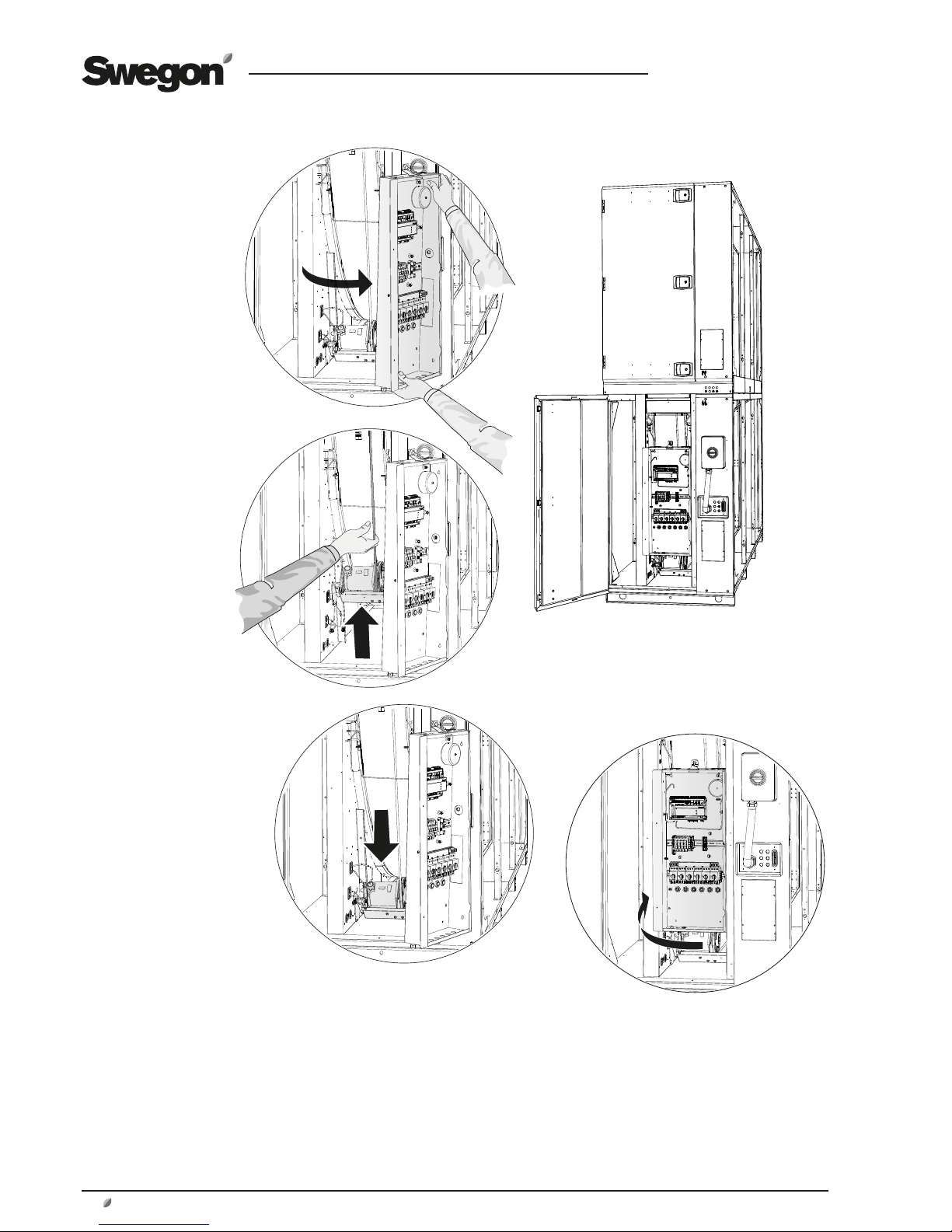
1.15 To Connect external cables
1.15.1 GOLD RX
To make the control unit accessible, open the inspection
door in front of the heat exchanger.
The decorative fitting can be used as a cable trough if you
need to run external cables. Dismantle the decorative fittings and fold back an appropriate number of ”tongues”
in the ends of the decorative fittings and run cables
through cable grommets in the decorative fitting of the
heat exchanger section. Refit the decorative fittings. Run
the cables further in to the electrical equipment cubicle
through the rubber diaphragm in front of the cubicle on
the heat exchanger section. Dismantle the service hatch to
enable you to run the cables. See illustration.
NOTE! External communication cables outside the air
handling unit should be positioned at a min. distance of
100 mm from energized cables.
Decorative fitting
Cable Service hatch
Control circuit board inside the
electrical equipment cubicle
1.15.2 GOLD CX
To gain access to the control unit, remove the cover panel
on the lower part of the coil heat exchanger and the
blanking plate of the electrical equipment cubicle.
The decorative fitting can be used as a cable trough if you
need to run external cables. Dismantle the decorative fittings and fold back an appropriate number of ”tongues”
in the ends of the decorative fittings and run cables
through cable grommets in the decorative fitting of the
heat exchanger section. Refit the decorative fittings. Run
the cables further into the electrical equipment cubicle
through the rubber diaphragm in front of the electrical
equipment cubicle on the heat exchanger section. See
illustration.
N.B.! External communication cables outside the air handling unit should be positioned at a min. distance of 100
mm from energized cables.
Decorative fitting
Cable Blanking plate, electri-
cal equipment cubicle
Cover panel
Control circuit board inside the
electrical equipment cubicle
Page 29

GB.GOLDINE120.130915
Swegon reserves the right to alter specifications.
www.swegon.com 29
2. Dimensions
2.1 GOLD RX 100/120
56* NO
56
M
N
P
P
77 3186
77
1048
1000 10481048122
45
137
Power connection
* The air handling unit is supplied without end connection panel if a duct accessory housed in an insulated casing will be connected.
Individual weights
Filter section
GOLD 100/120: 529 kg/pc.
Fan section
GOLD 100: 834 kg/pc.
GOLD 120: 968 kg/pc.
Heat exchanger section, mounted
GOLD 100/120: 1,174 kg .
Heat exchanger section, supplied in two casing sections + rotor
Lower casing section = 494 kg
Upper casing section = 270 kg
Rotor = 410 kg)
Transport cradle = 190 kg
Size A B D E F G H I J K L M N O P Weight, kg
100 1126 3340 1070 191 120 0 2400 3440 520 210 470 3322 800 170 2500 172 0 3900
120 112 6 3340 1070 191 120 0 2400 3440 520 210 470 3322 800 170 2500 1720 416 8
1.16 Installation of pipework package
(GOLD CX only)
For details on how to install the pipework package, see
separate instructions for the TBXZ-42 pipework package.
Page 30

GB. GOLDINE120.130915
Swegon reserves the right to alter specifications.
30
www.swegon.com
2.2 GOLD CX 100/120
Filter section
GOLD 100/120: 529 kg/pc.
Fan section
GOLD 100: 834 kg/pc.
GOLD 120: 968 kg/pc.
Heat exchanger section
GOLD 100/120: 880 kg /pc.
Power connection
Size A B D E F G H I J K L M N O P Weight, kg
100 1126 3340 1070 191 120 0 2400 3440 520 210 470 3322 800 170 2500 172 0 4486
120 112 6 3340 1070 191 120 0 2400 3440 520 210 470 3322 800 170 2500 1720 4754
56*
56
M
P
P
NO
N
137
77 3186 77
1048
1000 10481048122
45
Individual weights
Page 31

GB.GOLDINE120.130915
Swegon reserves the right to alter specifications.
www.swegon.com 31
3. Wiring terminals, control unit
SD
WLAN
CPU 1
CPU 2
1A2B3
GND4+5-6+7-8+9-
10+11-12+13
-
SA TempCom 5Com 4Com 3Com 2Com 1
14+15-16+17-18+19
-
Heat Cool
20C21NO22C23NO24C25NO26C27NO28P29G30G031G32
G0
24V AC
Sensor 1 Sensor 2 Sensor 4Sensor 3 Com 6 Com 7 Com 8 Com 9 Com 10 Com 11
+33-34G35G036Y37U
38 39 40
24V AC In
41 42
18V AC In
45 46
230V AC In
4743 44
230V AC Out
Digital inputs, terminals 4-17, are of extra-low voltage type. Analogue inputs, terminals 18-19 have an input impedance of 66 kΩ.
Wiring
terminal
Function Remarks
1,2,3 Connections for EIA -485 1= Communication connection A/RT+, 2= Communication connection B/RT–, 3= GND/COM.
4,5 External stop Stops the air handling unit by opening the circuit. On delivery, this function is fitted with a jumper. If
the connection is interrupted, the air handling unit will stop.
6,7 External fire/smoke function 1 External fire and smoke function. On delivery, this function is fitted with a jumper. If the connection is
interrupted, the function will trip and initiate an alarm.
8,9 External fire/smoke function 2 External fire and smoke function. On delivery, this function is fitted with a jumper. If the connection is
interrupted, the function will trip and initiate an alarm.
10,11 External alarm 1 External contact function. Optional: Normally open/normally closed.
12,13 External alarm 2 External contact function. Optional: Normally open/normally closed.
14,15 External low speed External contact function. Overrides the time switch from stop to low speed operation.
16,17 External high speed External contact function. Overrides the time switch from stop or low speed to high speed operation.
18,19 Demand control Input for 0-10 VDC. The input signal influences the supply air/extract airflow setpoint if the unit is
operating in the demand control mode. For connection of a sensor, for example CO
2
, CO and VOC
20,21 Circulation pump, heating circuit Independent contact, max. 5 A/AC1, 2 A/AC3, 250 VAC. Closes on a heating load.
22,23 Circulation pump, cooling circuit or
cooling on/off, 1-step operation
Independent contact, max. 5 A/AC1, 2 A/AC3, 250 VAC. Closes on a cooling load.
24,25 Cooling, on/off, 2-step operation Independent contact, max. 5 A/AC1, 2 A/AC3, 250 VAC. Closes on a cooling load.
26,27 In-service indication Independent contact, max. 5 A/AC1, 2 A/AC3, 250 VAC. Closes when the unit is operating.
28,29,30 Damper control 24 VAC. 28= Controlled 24 VAC (G), 29= 24 VAC (G), 30= 24 VAC (G0).
31,32 Control voltage
1)
24 VAC control voltage. Terminals 31-32 are loaded with a total of 16 VA. Opened by means of the
safety isolating switch.
33,34 Reference voltage Output for constant 10 VDC. Max. permissible load: 8 mA.
35,36,37,38 Control, recirculation damper The recirculation damper can be loaded with max. 2 mA at 10 VDC. 35= 24 V AC (G), 36= 24 V AC (G0),
37= 0-10 V DC control signal, 38= 0-10 VDC feedback signal.
The max permissible common load on terminals 31-32, outputs for Heat/Cool and damper output (terminals 28-30) is 50 VA.
1)
GOLD 100/120: If more than 16 VA is required, use wiring terminals 201 (G) and 202 (G0). Terminals 201-202 can be loaded
with a total of max. 48 VA.
The max. permissible load on the
corresponding connection is 16 VA.
Page 32

GB. GOLDINE120.130915
Swegon reserves the right to alter specifications.
32
www.swegon.com
 Loading...