

Swegon ELQZ-2-504 series, ELQZ-2-504 GOLD, ELQZ-2-504 COMPACT Installation Instructions Manual
Page 1
3. Push the intermediate plate together with cover
upward and hold firmly against the base plate.
GB.ELQZ504480.110202
Specifications are subject to alteration without notice.
www.swegon.com 1
Installation Instructions for theELQZ-2-504 Air Quality Sensor
GOLD/COMPACT
1. General
The carbon dioxide content of the indoor air is an effective
indicator of how many occupants are in a room and the
degree of ventilation required to maintain the air quality
we need. Ventilation control based on CO2 measurements
guarantee the adequate supply of fresh air, and at the
same time keeps energy costs as low as possible.
2. Function
Demand Control
Set the air handling unit to “DEMAND REGULATION”
under the “FAN REGULATION” (CONTROL) function menu
(see the Operation and Maintenance Instructions).
Set the setpoint required as a percentage of the sensor’s
operating range.
If a setpoint of 1000 ppm is required, for instance, set
the setpoint to 50%. Enter the setting under the “FLOW/
PRESSURE” menu group (see the Operation and Maintenance Instructions).
ReCO
2
Set the GOLD unit to ”CO2” under the ”ReCO2” Function
menu (see the Operation and Maintenance Instructions).
Set the setpoint required as a percentage of the sensor’s
operating range.
If a setpoint of 1000 ppm is required, for instance, set
the setpoint to 50%. Enter the setting under the “FLOW/
PRESSURE” menu group (see the Operation and Maintenance Instructions).
3. Mounting
Locate the sensor where the indoor climatic conditions are
typical for the premises. Avoid any spot where the sensor
would be exposed to direct draught or poor air mixture. We
advise locating the sensor at least 2 metres above the
floor to minimize the risk of physical damage or inaccurate
readings due to direct exposure to exhaled air. Access to
the sensor is needed for checking its function and servicing only.
1. Route the cable to where the sensor is to be located.
The cable can be recessed in the wall or other surface and
should then be passed into the air quality sensor through
its bottom section. If the wire is surface-mounted, it can
be passed into the sensor through one of the knockout
lead-throughs in the top of the sensor.
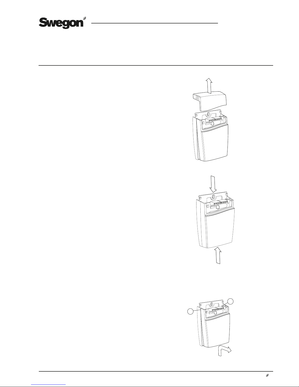
2. Back off the screw and pull the top section straight
upward.
4. Bend the intermediate plate with cover obliquely
outward and detach it from the hooks. 1
1
1
Page 2
GB.ELQZ504480.110202
Specifications are subject to alteration without notice.
2
www.swegon.com
4. Technical Data
Supply voltage 24 V AC ± 20%
Frequency 50/60 Hz
Power consumed 3 W
Output signal 0–10 VDC
Measuring range 500–1500 ppm
Accuracy* ± 1% of the measuring range
± 5% of the reading
Warm-up period < 1 min.
Response time < 2 min.
Wiring nuts for max. 1,5 mm²
Enclosure Class IP 20
Operating temperature 0 till +50 °C
Storage temperature -20 till +70°C
Dimensions (H×W×D) 120×82×30
*The accuracy is defined for continuous operation (at least three weeks
after installation).
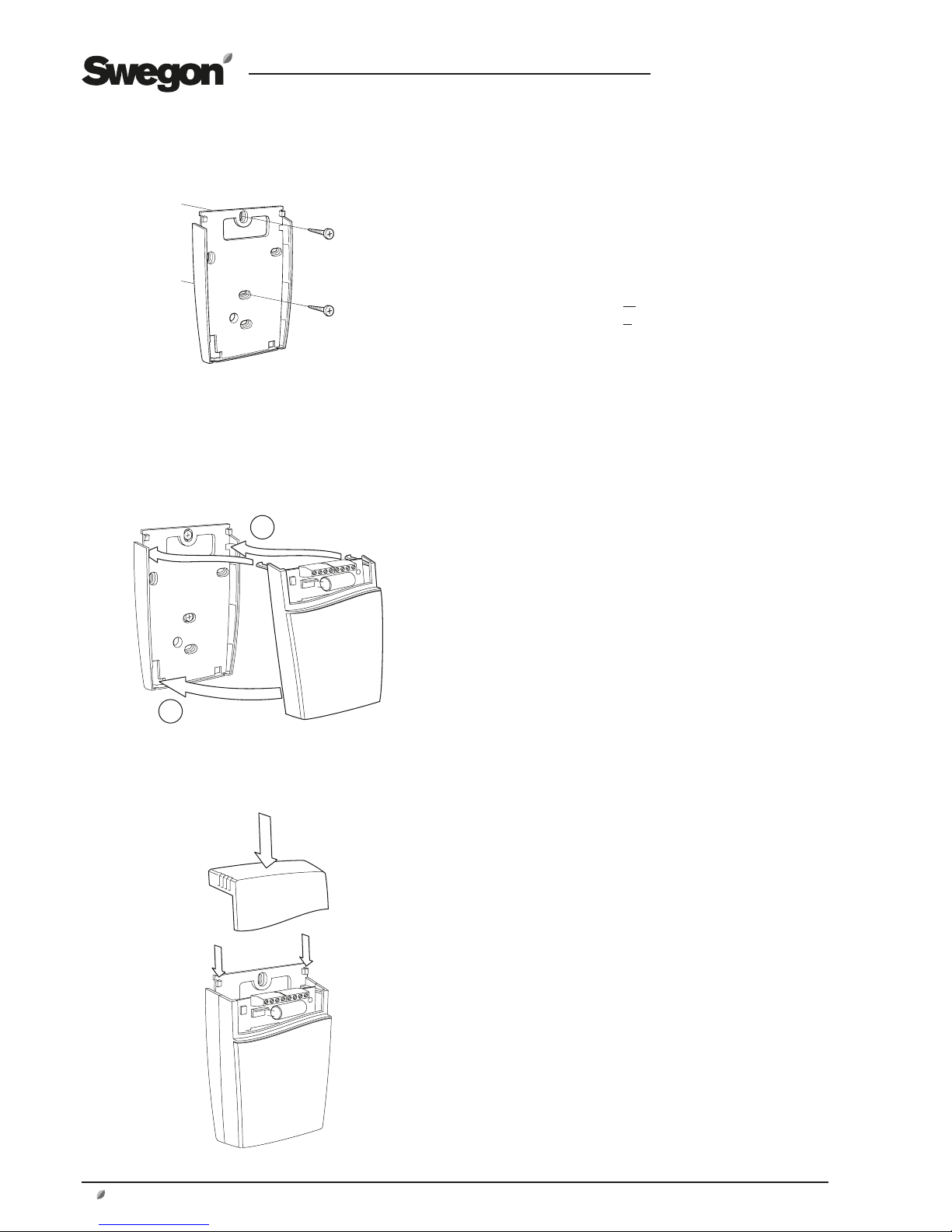
5. Secure the base plate by means of screws to the wall.
The screw head should be max. 4 mm.
A
B
6. A Insert the hooks into the holes in the upper
section of the base plate.
B Press the front against the base plate until its
hooks lock into the bottom edge of the front.
7. Push in the top section under the locking hooks in the
base plate and secure it in position by means of the screw.
Page 3

GB.ELQZ504480.110202
Specifications are subject to alteration without notice.
GOLD RX/PX/CX/SD
www.swegon.com 3
5. Electrical Connections
A qualified electrician should wire electrical connections in
accordance with local regulations.
Demand Control
G+ 1
2
3
G0
20% 0%
Out 1
Out 2
1
G0
G
2
3
20
19
Air quality sensor
IQnomic control unit
GOLD RX/CX
ReCO
2
IQnomic Plus
Air quality sensor
G+ 1
2
3
G0
20% 0%
Out 1
Out 2
1
31
61 G0
60 G+
33
2
A
B
31
33
3
3
Exhaust air fan
Supply air fan
IQnomic control unit
Starting
point
Current
Voltage
Current
Voltage
GOLD RX/PX/CX/SD
A = Control of supply air fan
B = Control of extract air fan
Starting
point
Current
Voltage
Current
Voltage
Applies to GOLD size 100/120 only:
If the total load on wiring terminals
58-59 and 60-61 is higher than 16
VA,you should wire the leads to terminals 201 (G) and 202 (G0). Wiring
terminals 201-202 can be loaded with
a total of max. 48 VA.
Page 4

GB.ELQZ504480.110202
Specifications are subject to alteration without notice.
Demand Control
G+ 1
2
3
G0
20% 0%
Out 1
Out 2
1
35
10 G0
9 G+
37*
2
3
IQnomic control unit
GOLD LP/COMPACT
GOLD LP/COMPACT
*Demand regulation (control) should be selected for
the one fan and slave control should be selected to the
other fan if so desired.
4
www.swegon.com
Air quality sensor
Starting
point
Current
Voltage
Current
Voltage
 Loading...