

Page 1
DETECT SMEa
10
10
Installation – Commissioning – Maintenance
Installation
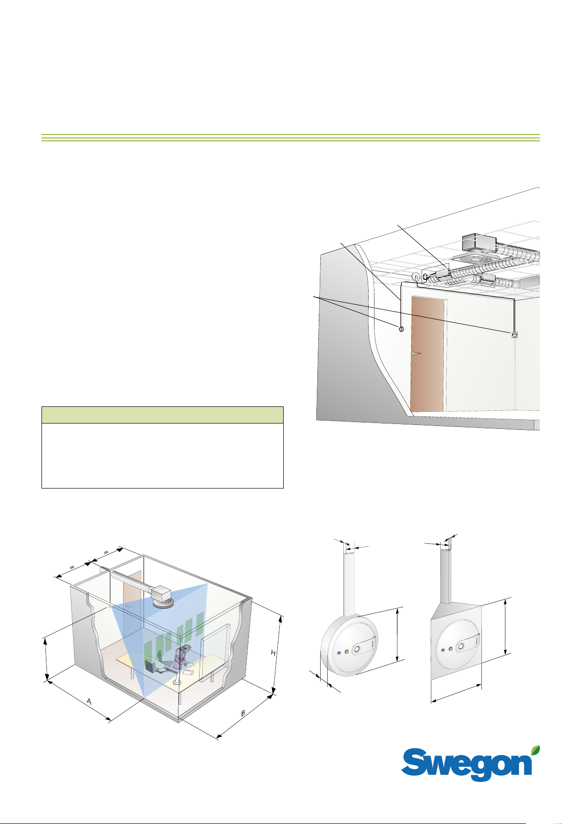
The presence detector is available in two types, wall mounted or corner mounted. Included at delivery is a 10 m cable
for connection to ADAPT Damper. Install the detector between 1,2 to 1,5 meters above floor level to
possible detection, preferably in a spot that enables detection of the whole room
. The detector must not be exposed to
direct sun light. Note that cable duct is not included at delivery.
To achieve best possible detection, install the detector turned
horizontally as examples shown in figure 3.
Detection
The presence detector is divided in sectors, 6 placed
horizontally and 3 vertically (not shown in figures). For
detection to take place, movement between two sectors
is required. The further away from the unit this happens,
the larger the movement required, as the sectors grow
larger with distance. In figure 1, the central sectors are
highlighted in green. Sector size corresponds approximately to 1/6 of the value from measurement B.
Occupancy presence sensor – detection area
*)
A
1,5 2,6 3,0 0,4
*)
B
H
provide the best
*)
B/6
*)
20120312 / Art: 1545189
Maintenance
Normally maintenance-free. To clean, dust off or wipe with
a damp cloth.
2,5 4,5 4,0 0,8
4 7,0 5,6 1,2
6 10 7,6 1,7
B/6 corresponds to the size of a detection sector.
*)
Measures are displayed in meters.
1,5
Figure 2. Placement of the presence detector.
1. ADAPT Damper
2. Cable duct min. 10x20 mm (not included in delivery)
3. Presence detector, DETECT SME (wall or corner mounted).
20
20
Figure 3. Dimensions, wall mounted and corner mounted type.
20
110
Ø 110
110
Figure 1. Detection area when mounted 1,5 m above floor level.
The presence detector is placed at the middle of the endwall in
the room. Max, recommended room depth is 6 m.
1
Page 2
DETECT SME
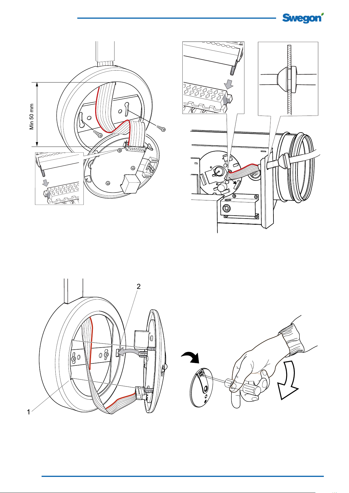
Figure 4. Installing a cable duct and the detector module to a
wall. Connect the cable to the socket, ensure that the socket is
turned correctly, enabling the plastic pin to fit the track of the
receptable socket.
Figure 6. Connection to ADAPT Damper.
1. Press out the knockout to open up the hole on the side.
2. Pull through the cable holding the rubber collet and secure
the collet firmly in the hole.
3. Connect the cable to the socket in the circuit board, ensure
that the socket pin is placed correspondingly to designated track
of the receptable socket.
Figure 5. Install the detector cap according to the figure, ensure
that the hitches are fitted correctly (1), then snap-on the cap into
the designated track (2)
Figure 7. Principle for opening the detector cap. Insert a screwdriver into the the gap next to the Swegon-symbol and bend
carefully towards the centre to open.
2
Swegon reserves the right to alter specifications. 20120312 www.swegon.com
 Loading...