

Swegon CoolDX 08-1, CoolDX 20-1, CoolDX 08-2, CoolDX 12-2, CoolDX 20-2 Installation And Maintenance Instructions Manual
...Page 1
GB.COOLDX.INST.090301
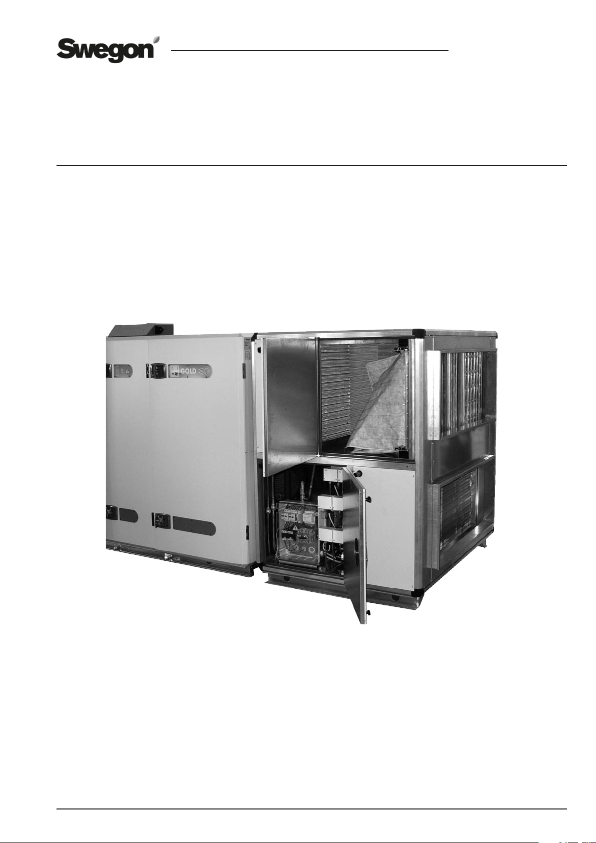
CoolDX COOLING UNIT
Installation and Maintenance Instructions
Sizes 08-60
Page 2
GB.COOLDX.INST.090301
We reserve the right to alter specifications.
2
www.swegon.com
CONTENTS
1. General Survey 3
1.1 General 3
1.2 Basic function diagram 4
2 Safety instructions 5
2.1 Safety switch/mains power switch 5
2.2 Risks 5
2.3 Electrical equipment 5
2.4 Authorisation 5
2.5 Identification decals 5
3 Installation 6
3.1 Unloading/transport within the building site 6
3.1.1 Lifting using a forklift truck 6
3.1.2 Lifting using a crane 6
3.2 Arrangement 6
3.3 Docking configurations 7
3.3.1 Height adjustment to height of GOLD/water trap 8
3.3.2 Connection to GOLD Units, CoolDX Size 08-12 8
3.3.3 Connection to GOLD Units, CoolDX Size 20-60 9
3.3.4 Duct connection, CoolDX size 08-12 9
3.3.5 Duct connection, CoolDX sizes 20-60 9
3.3.6 Condensate drainage from cooling coil 9
5 Commissioning 12
5.1 Preparations 12
5.1.1 Before initial start up 12
5.1.2 Starting up 12
5.1.3 In-service pressure switches 12
5.1.4 Phase-sequence monitor 12
5.1.5 Remedial action if wrong phase sequence 12
6 Alarms 12
7 Maintenance 13
7.1 Cleaning 13
7.2 Handling of refrigerant 13
7.3 Annual inspection 11
7.4 Servicing 13
8 Troubleshooting and leakage tracing 14
8.1 Troubleshooting Schedule 14
9 Dimensions 15
9.1 CoolDX 08 15
9.2 CoolDX 12 15
9.3 CoolDX 20-40 15
9.4 CoolDX 60 15
3.3.7 Supply air filter 9
3.3.8 Condensation barrier mat 10
4 Electrical connections 11
4.1 Connection to power supply 11
4.2 To connect the communication cable 11
10 General technical data 16
11 Electrical equipment 17
12 Internal Wiring Diagram 18
12.1 CoolDX 08-40, all capacity variants, and size 60,
capacity variant 1 18
12.2 CoolDX 60 Capacity variant 2 19
12.3 CoolDX 60 Capacity variant 3 20
13 Commissioning Record 21
Page 3
GB.COOLDX.INST.090301
We reserve the right to alter specifications.
www.swegon.com
3
1. GENERAL SURVEY
1.1. General
Cooling unit CoolDX
Cooling unit CoolDX is a complete cooling unit for comfort cooling in air handling systems. All the components
are fully wired, have fully connected refrigeration circuits
and are collected inside a common casing. The casing is
fabricated of aluminium profiled sections held together by
plastic corner pieces. The panels are of sandwich design
and consist of a 0.7-1 mm thick galvanized sheet steel
outer skin with painted visible surfaces (colour: NCS 2005
Y 30R), 1 mm thick aluminium-zinc plated sheet steel
inner skin and 35 mm thick intervening expanded polyurethane isolation.
The cooling coil and condenser are fabricated of copper
tubes and profiled aluminium fins; the casing is made of
galvanized sheet steel.
The cooing units are tested prior to delivery.
The CoolDX is available in 16 output variants which are
divided into six physical sizes, specially suited for the size
08-60 GOLD units.
Compressors
Size 60 units in output variant 2 and 3, contain a piston
compressor and a scroll compressor, all other sizes/output
variants contain two piston compressors each.
Completely direct-acting system
The CoolDX has a completely direct-acting system. It has
an evaporation coil for direct-evaporating refrigerant on
the cold side and a condenser coil on the hot side.
Refrigerant
The CoolDX has double refrigerant circuits separated from
each other. Type R407C refrigerant is used. The refrigerant
circuits are charged on the delivery. At present, this refrigerant has no known influence on the ozone layer and no
known future restrictions are anticipated.
Refrigerant volume
See section 10. General technical data.
Duty to report
If the total volumetric weight of the refrigerant filled into
the cooling system exceeds 10 kg, a report must be submitted to the local supervisory authority.
Annual inspection
If the volumetric weight of the refrigerant in the cooling
unit exceeds 3 kg, an annual inspection by an accredited
inspectorate is required. All the CoolDX units (except size
8, output variant 1) should be checked once a year.
ISO 9001 Quality Management and ISO 14001 Environmental Management Systems
We at Swegon are deeply involved in the maintenance of
our certified quality management system defined by ISO
9001 and our certified environmental management system defined by ISO 14001.
Page 4

GB.COOLDX.INST.090301
We reserve the right to alter specifications.
4
www.swegon.com
1.2 Basic function diagram
COND
VSH2
FD1FD2
HP
HP
BP1-3
IPL1IPL2
M1 M2
VET1VET2
EVAP
VSL1
LP
BP1
VSL2
COND Condenser
VSH1 Overpressure protection
VSH2 Overpressure protection
BP1-3 Pressure limiting switch for high pressure 26 bar
BP1 Pressure limiting switch for low pressure 2,5 bar
BP2-3 Pressure limiting switch for high pressur 26 bar
BP2 Pressure limiting switch for low pressure 2,5 bar
BP1-2 Alarm pressure switch for high pressure 28 bar
BP2-2 Alarm pressure switch for high pressure 28 bar
M1 Compressor
M2 Compressor
VSL1 Underpressure protection
VSL2 Underpressure protection
EVAP Evaporator
VET1 Expansion valve with thermostat
VET2 Expansion valve with thermostat
IPL1 Sight glass, refrigerant circuit 1
IPL2 Sight glass, refrigerant circuit 2
FD1 Filter drier
FD2 Filter drier
Operation
There are two refrigerant circuits in the cooling unit. The
circuits are separate from one another.
Each circuit is equipped with a finned condenser, a finned
evaporator and a compressor.
The two compressors have different capacity, which enables control in 3 steps.
The gaseous refrigerant is compressed by compressors M1
and M2 and from there moves on to condenser COND,
where it is chilled by the extract air and is condensed to
liquid form.
The pressure and the temperature decrease as the refrigerant in fluid form flows through expansion valves VET1
and VET2.
HP
BP2-2BP1-2
HP
BP2-3
LP
BP2
From the expansion valves the refrigerant moves on to
evaporator EVAP, where the refrigerant evaporates and
chills the outdoor air.
From evaporator EVAP, the evaporated refrigerant is conveyed further to the suction side of the compressors where
it is again compressed.
Control
The cooling capacity is regulated in three binary steps by
having one or two compressors in operation.
The cooling compressors are controlled from the GOLD
unit via relays on the IQnomic Plus module mounted in the
CoolDX.
Step 1: When cooling is needed, Compressor M1 is started.
Step 2: If more cooling is needed, Compressor M2 starts
and at the same time Compressor M1 stops. An adjustable time delay (a step duration of 300 seconds) ensures
that Compressor M2 will not start until Compressor M1 is
operating at full capacity.
Step 3: If even more cooling is needed, Compressor M1 is
restarted and is run at the same time as Compressor M2.
This third cooling step is also delayed by a preset time delay setting. In addition, the restarting time (480 seconds)
for Compressor M1 shall have expired.
If less cooling is needed and the compressors are subsequently switched out step-by-step, there will be no delay
between compressors. The restarting time (480 seconds)
for Compressor M1 shall have expired to enable it to start
again in Step 1 after it has been operated in Step 3.
If any compressor is stopped, the restarting time must
expire before a restart can take place. The restart time is
calculated from one start to the next start.
Low pressure switches BP1/BP2 and high pressure switches
BP1-3/BP2-3 (in-service pressure switches for the respective circuit) ensure that the system pressure is within predetermined limits.
If the pressure in the cooling circuit becomes too low, or
if the pressure in the condenser circuit becomes too high,
the compressor is stopped and the text PRESSURE LIMITING is displayed alternately in the hand-held micro terminal of the GOLD air handling unit.
When the restart time has expired, the compressors will try
to restart.
If the pressure increases more, high pressure switches
BP1-2 and BP2-2 will trip and stop the GOLD unit and the
CoolDX cooling unit.
Alarms 85 and 86 will be displayed in the hand-held micro
terminal of the GOLD unit.
Pressure switches BP1-2 and BP2-2 can be manually reset
by pressing a button under each protective sock on the
upper side of the pressure switch. This can be done without removing the protective sock.
Page 5
GB.COOLDX.INST.090301
We reserve the right to alter specifications.
www.swegon.com
5
2 SAFETY INSTRUCTIONS
2.1 Safety switch/mains power switch
The safety isolating switch is positioned on the inspection
side of the cooling unit.
The safety isolating switch should not be used for starting
or stopping of the cooling unit.
To ensure that the CoolDX is switched off: stop the air
handling unit or briefly switch off the cooling unit via the
hand-held micro terminal. See the GOLD Operation and
Maintenance Instructions.
On completing the above, the safety isolating switch can
be used for switching off the power supply.
Caution!
Always switch off the safety switch whenever you
service the unit, unless otherwise stated in relevant
instructions
2.2 Risks
Warning
Always isolate the power supply before starting any
work in the refrigerant circuit or the electrical system.
Warning
The inspection door of the GOLD unit may not be opened while the unit is in operation. Positive pressure inside the unit will cause the door to fly open and possibly
cause personal injury.
2.3 Electrical equipment
The electrical equipment of the cooling unit is housed in
a separate cubicle located behind one of the inspection
doors.
2.4 Authorisation
Only qualified and authorised electricians shall be permitted to install electrical wiring in the unit.
Only an accredited refrigeration company shall be permitted to modify or repair the refrigeration circuits.
Other modifications in the unit should only be made by
service personnel trained by Swegon.
2.5 Identification decals
The unit identification decal indicating type designation,
serial number, refrigerant volume, etc. is affixed to the
door of the cooling unit.
Type designation: COOLDX-aa-A-c-d-e
GOLD size
Warning
Under no circumstances may the refrigerant circuits be
opened by unauthorised personnel, since they contain
gas under high pressure.
Risk areas where exposure to refrigerant could occur
Practically the whole area inside the cooling unit is a risk
area. For particulars on how to deal with leakage, see
Section 7.2.
Type R 407C refrigerant is used.
Capacity variant
Page 6
GB.COOLDX.INST.090301
We reserve the right to alter specifications.
6
www.swegon.com
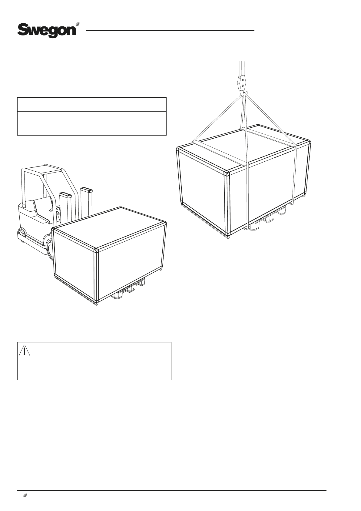
3 INSTALLATION
3.1 Unloading/transport
within the building site
Important!
All transport should be carried out with the cooling unit
in the horizontal position.
3.1.1 Lifting using a forklift truck
Warning
The unit has a high centre of gravity! Carefully lift the
cooling unit!
3.1.2 Lifting using a crane
Position two line spreaders at the upper side of the cooling
unit and two under the underside of the pallet or under
the cooling unit and lift in the pallet (or in the base frame
of the cooling unit if the unit is not delivered on a pallet).
3.2 Arrangement
Position the CoolDX cooling unit at suitable place in the
fan room.
Allow an open space around the safety isolating switch/
mains power switch for servicing in accordance with applicable electrical safety regulations.
The unit can be positioned with its backside against a wall;
however it is advisable to position it at a distance of approx. 1 metre away from a wall to make it easier to service
the rear compressor.
See sketch.
Page 7
GB.COOLDX.INST.090301
We reserve the right to alter specifications.
www.swegon.com
7
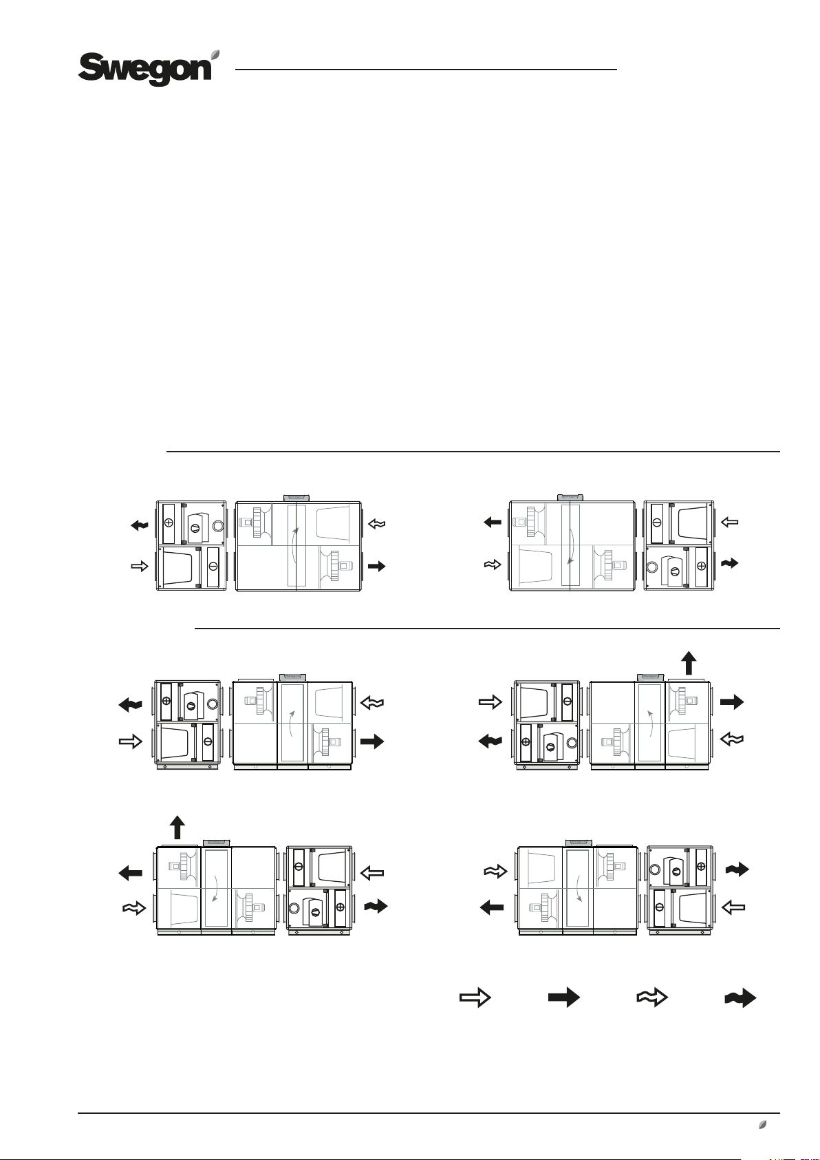
3.3 Docking configurations
The design of the CoolDX cooling unit enables it to be
docked to the outdoor air and exhaust air side of the
GOLD air handling unit. See sketch!
The dimensions and capacities of the CoolDX are designed
for connection to size 08-60 GOLD air handling units.
For a list of the cooling unit sizes and capacities that
match a given size of GOLD unit, see Section 10. General
Technical Data.
CoolDX 08
CoolDX 12-60
Cooling coil in lower level/GOLD fan arrangement 1 Cooling coil in upper level/GOLD fan arrangement 2
Right hand version Left hand version
Right hand version
Left hand version
Cooling coil in upper level/GOLD fan arrangement 1 Cooling coil in lower level/GOLD fan arrangement 2
Outdoor air Supply air Extract air Exhaust air
Page 8

GB.COOLDX.INST.090301
We reserve the right to alter specifications.
8
www.swegon.com
50
3.3.1 Height adjustment to height of GOLD/
water trap
CoolDX, size 08
In combination with GOLD RX 08
The design of the GOLD unit makes it necessary to mount
it on a stand or some other form of support, so that its
inspection doors can be opened. The stand is available as
an accessory.
A corresponding stand is also available as accessory for the
CoolDX.
The heights of the stands are matched to one another and
also provide space for a water trap, if required, for connection at the lower section (right-hand version).
In combination with the GOLD PX 08
The air handling unit is supplied on a 180 mm high base
frame.
A corresponding base frame is also available as an accessory for the CoolDX. The heights of the base frames
are matched to one another and also provide space for a
water trap, if required, for connection at the lower section
(right-hand version).
CoolDX, sizes 12-40
The GOLD air handling unit and the cooling unit CoolDX
are supplied with 100 mm high base beams.
Applicable to cooling coil in lower level:
If a water trap (accessory) is fitted, the GOLD unit and
the cooling unit must be raised at least 50 mm to provide
space for the water trap. Adjustable support feet (accessories) can be appropriately fitted to the base beams for
this purpose.
3.3.2 Connection to GOLD Units, CoolDX Size 08-12
Insert rubber ring seals (2 rings, not included in the supply)
into the circular outdoor air and exhaust air connections of
the GOLD unit respectively. See the installation instructions
for the GOLD, as well.
If the CoolDX is to be docked directly against the GOLD
unit:
Use a forklift truck or a hand truck to position the CoolDX
against the GOLD unit as described in Section 3.3 Docking Configurations. Make sure that the rubber seals on
the GOLD unit engage into the duct connections on the
CoolDX unit. See sketch!
Important! Be careful to prevent damage to the unit and
the rubber ring!
Rubber ring seal
CoolDX
GOLD
Distance, GOLD/CoolDX
CoolDX, sizes 60
The GOLD air handling unit and the cooling unit CoolDX
are supplied with 100 mm high support feet. The support
feet can be removed or left on the unit.
Applicable when cooling coil in lower level:
If a water trap (accessory) is fitted, the GOLD unit and the
cooling unit must be raised at least 50 mm above the base
beams to provide space for the water trap. This can appropriately be done by leaving the factory-fitted support feet
on the base beams. Or you can replace them with adjustable feet (accessory).
CoolDX
GOLD
If the CoolDX is to be located at another place:
Position the CoolDX at an appropriate place in the fan
room. Insert rubber ring seals (2 rings, not included in the
supply) into the relevant circular duct connections on the
CoolDX. See Section 3.3 Docking Configurations.
Connect the ducts between the GOLD unit and the
CoolDX unit.
It may be necessary to extend the communication cable
and necessary tubing (not included in the supply) depending on the distance between the GOLD unit and the
CoolDX unit.
Page 9

GB.COOLDX.INST.090301
We reserve the right to alter specifications.
www.swegon.com
9
71
3.3.3 Connection to GOLD units, CoolDX Sizes 20-60
Fit the sealing strip onto the GOLD unit’s outdoor air and
exhaust air connections respectively. See the installation
instructions for the GOLD, as well.
If the CoolDX is to be docked directly against the GOLD
unit:
Use a forklift truck or a hand truck to position the CoolDX
against the GOLD unit as described in Section 3.3 Docking
Configurations. Make sure that the connections on the
GOLD unit and the CoolDX unit are in alignment and are
close to one another.
Important! Be careful to prevent damage to the unit!
Joint the connections together with slip clamps (accessories: TBLZ-2-aa-08 slip clamps ). See the installation
instructions for the GOLD.
Distance, GOLD/CoolDX
CoolDX
The condensate discharge pipework shall be connected
across a water trap (accessory) to the drain connections of
the cooling unit and shall run with continuous slope to a
drain gulley.
Nipples in the
intermediate deck
Pressure
transducer
Interconnection nipples
White hose
Blue hose
CoolDX
GOLD
Extract air fan
Existing hoses for measuring
the pressure drop across the
filter in the GOLD
Duct connection
GOLD
If the CoolDX is to be located at another place:
Position the CoolDX at an appropriate place in the fan
room. Connect ducts between the GOLD unit and the
CoolDX unit, arranging the connections as described in
Section 3.3 Docking Configurations.
Joint the ducts and connection spigots together with slip
clamps (accessories: TBLZ-2-aa-08 slip clamps ). See the
installation instructions for the GOLD.
It may be necessary to extend the communication cable
and necessary tubing (not included in the supply) depending on the distance between the GOLD unit and the
CoolDX unit.
3.3.4 Duct connection, CoolDX Size 08-12
Fit rubber ring seals (not included in the supply) to the
CoolDX for connection to circular ducting. See the installation instructions for the GOLD, as well.
3.3.5 Duct connection, CoolDX Sizes 20-60
The size 20-60 CoolDX cooling units have rectangular connections. Use slip clamps (accessories: TBLZ-2-aa-08 slip
clamps) for jointing to ducts.
3.3.6 Condensate drainage from cooling coil
The cooling unit is equipped with a drain tray below the
cooling coil for collecting condensate that drips from coil
surfaces.
3.3.7 Supply air filter
The CoolDX is supplied with its own supply air filter. Consequently, the supply air filter in the GOLD unit should be
dismantled.
The hoses for measuring air pressure drop across the
supply air filter are supplied in the CoolDX and are connected inside the CoolDX at the factory. These hoses must
however be connected to supply air filter pressure drop
measurement hoses inside the GOLD unit. To do this,
proceed as follows:
Extend the hoses from the CoolDX unit, through the duct
connections of both units to the extract air fan space inside the GOLD unit. Disconnect the existing filter pressure
drop hoses from the pressure drop measurement nipples
in the intermediate deck of the GOLD. To prevent leakage,
use an appropriate sealant to seal the nipples in the intermediate deck.
IMPORTANT! Do not disconnect the hoses from the pressure transducer as doing so is likely to damage the hose
connections on the pressure transducer.
Connect the blue hose from the CoolDX to the blue hose
from the pressure transducer of the GOLD unit using the
interconnection nipples supplied. Connect the white hoses
in the same way. See above sketch.
IMPORTANT! There are other variants besides those
shown in the sketch. See Section 3.3 Docking Configurations.
Position and secure the hoses by means of bundling straps,
for example.
Page 10

GB.COOLDX.INST.090301
We reserve the right to alter specifications.
10
www.swegon.com
3.3.8 Condensation barrier mat
Install condensation barrier mats (supplied) on the interior
surfaces of the connections between the GOLD air handling unit and the CoolDX as illustrated below, to prevent
condensate from reaching metallic surfaces.
The condensation barrier mats are self-adhesive. Open the
inspection doors on the GOLD air handling unit and install
the mats from this side.
A
Cross section A-A
A
Open the inspection doors. Fit the condensation barrier mat
onto the interior surfaces of the
connections between the GOLD
unit and the CoolDX.
Page 11

GB.COOLDX.INST.090301
We reserve the right to alter specifications.
www.swegon.com
11
4 ELECTRICAL CONNECTIONS
Important
Electrical installations must be carried out by an authorised electrician.
4.1 Connection to power supply
Connection to the mains power supply must be wired
across the safety isolating switch on the front panel of the
cooling unit. Remove the four screws on the safety switch
enclosure and remove the lid. There are knockout holes on
the sides of the enclosure serving as cable lead-throughs.
Connect the 400 V power supply (5-conductor system,
except for the size 60 CoolDX in capacity variant 3 that has
a 4-conductor system) directly to the safety isolating switch,
which has four normally-closed contact functions (three for
the size 60 CoolDX, capacity variant 3). The terminal for the
incoming earth conductor is situated right next to the safety
switch. See sketch.
The ambient temperature and the way the cable is placed
must be taken into account when sizing the power cable.
Technical data, see Section 10.
Connect power
supply here
Factory
mounted
cables
4.2 To connect the communication cable
Only one communication cable is required for transferring
information between the controls of CoolDX and the GOLD.
All operating status and other information can be accessed
and read in the hand-held micro terminal of the GOLD unit.
The communication cable is pre-wired to the electrical
equipment inside the CoolDX unit and is coiled up behind
the inspection door.
The communication cable is to be lead out through the
predrilled hole in the cover plate on the inspection side of
CoolDX. First fit the rubber sleeve, supplied, into the predrilled hole to serve as a cable gland. Then lead the communication cable in a secure manner through the rubber sleeve
and from the CoolDX to the junction (wiring) hood of the
GOLD.
To connect the cable to the GOLD
Connect the communication cable to any of the bus connections on the control unit. See encircled area in sketch.
.
Use one of the holes in the oblong rubber clad cable
gland on the back side of the junction hood of the electrical cubicle, to extend the cable to control unit. See
sketch.
Push aside part of the cable gland to insert the communication cable through it. Connect the cable to an
optional bus connection on the control unit. Adjust the
length of cable inside the electrical cubicle and adjust its
position through the cable gland. Refit the cable gland
back to its correct position.
An extra outdoor air temperature sensor is required if
any of the following functions are activated in the GOLD
air handling unit: outdoor compensation, cooling step
blocking, cooling boost, summer night cooling, CoolDX
comfort control and pump control for the heating coil.
Use the TBLZ-1-30 accessory for mounting an outdoor
air temperature sensor in the ductwork upstream of the
CoolDX. Use the TBLZ-1-24/25 for installing the outdoor
air temperature sensor outdoors.
If outdoor air temperature readings are obtained via
communication to the GOLD air handling unit, then no
extra temperature sensor is needed.
Page 12

GB.COOLDX.INST.090301
We reserve the right to alter specifications.
12
www.swegon.com
1
1
2
3
4
5
6
7
8
9
0
P1 L1 L2
632457 12981011
13 181514 1617 19 242120 22 23
Rsf 077
CAREL
ok
alarm
5 COMMISSIONING
5.1 Preparations
5.1.1 Before initial start up
• The power supply must be connected.
• The communication cable to the GOLD air handling
unit should be connected to one of the connections
marked Internal EIA-485.
• Check that all fuses and protective motor switches are
on.
The control system of the GOLD has a pre-programmed factory
setting, which makes the cooling unit ready to use after basic
settings have been entered. The CoolDX function should be
activated. See the Operation and Maintenance Instructions for
the GOLD dealing with managing the menus in the hand-held
micro terminal.
5.1.2 Starting up
• Set the safety isolating switch of the cooling unit to
position ON.
• Check that light-emitting diode L2 on the IQnomic
Plus module steadily shines (24 V supply), and that
light-emitting diode L1 is flashing (communication).
The function selector switch should be in position 6.
• Check in the hand-held micro terminal of the GOLD
unit that Auto Operation has been selected as the air
handling unit’s cooling function (under Operation
Mode), and that CoolDX Economy or CoolDX Comfort
has been selected under Cooling Regulation.
• Go to the Manual Test Menu in the hand-held micro
terminal of the GOLD unit. See the Operation and
Maintenance Instructions for the GOLD unit.
Navigate to IQnomic Plus and CoolDX.
• Check: Start one compressor at a time. If any
compressor doesn’t start, an alarm will be initiated.
For the size 60, capacity variants 2 and 3, CoolDX
units, the rotation direction of compressor no. 2 is
important. See Section 5.1.4 Phase sequence monitor.
• Set the compressors to 0 (stop).
• Go back to the main menu.
• CoolDX is now ready for operation and will start when
there is a cooling load.
5.1.4 Phase-sequence monitor
The size 60 CoolDX, capacity variants 2 and 3, are equipped with
a phase sequence monitor for compressor 2.
The phase sequence monitor for capacity variant 2 is installed in
the electrical equipment cubicle, see illustration.
The phase sequence monitor for capacity variant 3 is integrated
with the compressor and is installed in its connection box. It lacks
visible indication LEDs.
Alarm 86, CoolDX K2 tripped, is displayed in the hand-held micro terminal of the GOLD unit. In the event that Alarm 86 trips,
this may be due to several causes: incorrect phase sequence,
tripped protective motor switch, tripped high pressure switch
(BP2-2) or the absence of control voltage.
Electrical equipment in the CoolDX
1
Applicable to size 60, capacity variant 2 only:
When LED 1 is lit, there are at least two phases.
When LED 2 is lit, the phase sequence is correct..
2
5.1.5 Remedial action if wrong phase sequence
Warning
May only be carried out by an authorised electrician or
trained service personnel.
• Stop the CoolDX by selecting SHUT OFF in the menu SETTINGS.
• Set the safety switch to position OFF on the CoolDX.
• Isolate the power supply to the CoolDX.
5.1.3 In-service pressure switches
The CoolDX has two in-service pressure switches in each cooling
circuit, one for low pressure and one for high pressure.
If the operating pressure, in any of the circuits, exceeds or drops
below a limit value, the relevant compressor is switched off. The
text CoolDX PRESSURE LIMITING is displayed in the hand-held
terminal until the pressure comes within the limit values again.
The compressor is permitted to restart when the restart delay has
expired.
Important
Check that the incoming power supply to the CoolDX is
isolated by measuring.
• Transpose the two phase wires on the incoming power
supply cable in order to obtain correct phase sequence
(direction of rotation).
• Reconnect on power supply to the CoolDX.
• Set the safety isolating switch to the ON position.
• Start the CoolDX as described in Section 5.1.2 Starting up.
6 ALARMS
For a description of the alarms, see the Operation and Maintenance Instructions for the GOLD.
Page 13

GB.COOLDX.INST.090301
We reserve the right to alter specifications.
www.swegon.com
13
7 MAINTENANCE
7.1 Cleaning
Use a vacuum cleaner and a damp cloth to clean the interior of the cooling unit, if needed.
Inspect the unit at least twice a year.
7.2 Handling refrigerant
Type R 407C refrigerant is used.
The refrigerant circuit is already charged when the unit is
delivered.
Warning
Under no circumstances shall unauthorised personnel be
permitted to open the refrigerant circuits, as long as gas
under high pressure is present in the circuits. Only the
technicians of an accredited refrigeration company shall
be permitted to modify or repair the refrigerant circuit s.
The CoolDX is equipped with a safety valve to prevent
excessively high pressure in the system if high temperatures caused by a fire, for example.
Important
Charging with refrigerant must be carried out according
to the recommendations of the refrigerant producer.
Avoid direct skin contact with the refrigerant.
Use close-fitting protective eyeglasses, protective gloves
and protective work clothing that cover the whole body.
Provide adequate ventilation/local extraction.
In the event of eye contact
Flush the eyes using an emergency eye-wash shower
(alternating with lukewarm water) for 20 minutes. Seek
a doctor.
In the event of skin contact
Thoroughly wash with soap and lukewarm water.
In the event of frostbite
Seek a doctor.
Important
Contact Swegon Service if you detect any refrigerant
leakage.
Warning
If refrigerant is exposed to fire or in some other way
becomes superheated in the atmosphere, poisonous
gases can form.
7.3 Annual inspection
An annual check carried out by an accredited inspectorate
is required if the volume of refrigerant in the cooling unit
exceeds 3 kg. See 10, General technical data.
Obligation to report
You are obligated to file a report with the local supervisory
authorities only if the total volume of refrigerant charged
in refrigerating units at a given company exceeds 10 kg.
7.4 Servicing
Only service personnel trained by Swegon shall be permitted to modify the cooling unit.
Page 14

GB.COOLDX.INST.090301
We reserve the right to alter specifications.
14
www.swegon.com
8 TROUBLESHOOTING AND
LEAKAGE TRACING
8.1 Troubleshooting Schedule
Symptom Possible cause Remedial measure
Compressor is not operating
Too low cooling capacity
The low pressure switch switches
off the compressor.
The high pressure switch switches
off the compressor.
Significant freezing on the
evaporator.
The voltage has been isolated.
Size 60, capacity variants 2 and 3: Incorrect phase
sequence.
The compressor safety circuit has been broken.
Defective compressor.
The voltage has been isolated.
Size 60, capacity variants 2 and 3: Incorrect phase
sequence.
No airflow or too low airflow across the evaporator.
Thermostat/control equipment incorrectly set or defective.
Inadequate refrigerant.
No airflow or too low airflow across the evaporator.
The expansion valve is defective.
The low pressure switch is defective.
No airflow or too low airflow across the condensor.
Excessively high exhaust air temperature
The high pressure switch is defective.
The expansion valve is defective or incorrectly set.
No airflow or too low airflow across the evaporator.
Check the operating/safety switch. Check the condition of the fuses.
Check and change the phase sequence.
Check, reset if needed.
Replace the compressor.
Check the operating/safety switch. Check the condition of the fuses. .
Check and change the phase sequence.
Check the airflow.
Adjust the setting or replace faulty components.
The cooling system is leaking. Tighten the leak and
charge with refrigerant.
Check the airflow.
Check, replace.
Check, replace.
Check the airflow.
Check the exhaust air temperature.
Check. replace.
Check. Replace or adjust setting
Check the airflow.
8.2 Leakage Tracing
As a preventive measure, the cooling system should be
inspected at least once per year to detect possible leakage.
The leakage tracing inspection must be documented.
If the cooling system is leaking, this will become apparent
firstly by impaired cooling performance, or if the leakage is
substantial, when the cooling unit does not operate at all.
If you suspect that the cooling system is leaking refrigerant, check the level of refrigerant in the sight glass located
on the liquid line of the cooling unit.
If you see continuous and a substantial amount of bubbling in the sight glass and the cooling unit operates at appreciably lower capacity than normal, the system is probably leaking. One or several bubbles appearing when the
cooling unit is started up, operation at reduced capacity or
normal operation need not necessarily indicate a refrigerant deficiency.
If it is bubbling in the sight glass and the cooling unit operates at appreciably lower capacity, call for qualified service
help.
N.B.! Maintenance work in the refrigerant system is permitted to be carried out only by an accredited inspectorate
(a company with requisite authorisation).
Page 15

GB.COOLDX.INST.090301
We reserve the right to alter specifications.
www.swegon.com
15
9 DIMENSIONS
46 46 5050 K
46 46
50
50
K
46 465050 K
9.1 CoolDX 08
9.2 CoolDX 12
9.3 CoolDX 20-40
CoolDX,
size
08 1250 990 1086 Ø 400
CoolDX,
size
12 1250 1199 1394 935 Ø 500
CoolDX,
size
20
30
40
L
(length)
mm
L
(length)
mm
L
(length)
mm
1250
1250
1250
B
(width)
mm
B
(width)
mm
B
(width)
mm
1294
1595
1886
H
(height)
mm
H
(height)
mm
H
(height)
mm
1394
1696
1986
Duct connection
K
mm
connection
K
mm
connection
1036
1000 x 400
1336
1200 x 500
1706
1400 x 600
mm
Duct
mm
Duct
mm
9.4 CoolDX 60
Supplied on 100 mm high support feet. Can be removed or left on when
the unit is in place. Has provision for adjustable support feet
CoolDX,
size
60 1250 2253 2353 2075 1600 x 800
L
(length)
mm
B
(width)
mm
H
(height)
mm
K
mm
Duct
connection
mm
Page 16

GB.COOLDX.INST.090301
We reserve the right to alter specifications.
16
www.swegon.com
10 GENERAL TECHNICAL DATA
Cooling system CoolDX
CoolDX Capacity Rated Rated Refrigerant Minimum Power supply Weight
Size variant cool. power power req. data R407c (kg) airflow (kg)
(kW) 1) (kW) Circuit 1 Circuit 2 (m3/s)
08-1 1 10 3,69 1,2 1,6 0,46 3-phase, 400V, 16A 247
08-2 2 14 5,02 1,2 2,2 0,46 3-phase, 400V, 16A 257
12-1 1 14 4,95 1,3 2,7 0,68 3-phase, 400V, 16A 305
12-2 2 20 6,94 1,4 2,9 0,9 3-phase, 400V, 20A 332
20-1 1 14 4,95 1,3 2,7 0,68 3-phase, 400V, 16A 323
20-2 2 20 6,94 1,4 2,9 0,9 3-phase, 400V, 20A 351
20-3 3 26 9,88 2,3 3,3 0,9 3-phase, 400V, 25A 373
30-1 1 27 9,00 2,0 4,2 1,25 3-phase, 400V, 25A 440
30-2 2 32 10,66 2,2 4,7 1,5 3-phase, 400V, 32A 486
30-3 3 45 16,47 3,4 5,6 1,5 3-phase, 400V, 40A 527
40-1 1 39 12,24 2,6 5,3 1,8 3-phase, 400V, 40A 572
40-2 2 45 14,54 2,9 5,9 2,1 3-phase, 400V, 40A 605
40-3 3 58 21,42 5,1 8,1 2,1 3-phase, 400V, 63A 672
60-1 1 58 18,94 4,9 8,0 2,6 3-phase, 400V, 50A 720
60-2 2 69 20,20 4,9 8,0 3,2 3-phase, 400V, 63A 819
60-3 3 95 33,18 7,9 11,9 3,2 3-phase, 400V, 80A 944
1)
For an outdoor temperature of 28°C, 50% RH and an extract air temperature of 25°C.
Sizing
There are many factors that influence what size of cooling
unit is required.
The CoolDX units have been designed to enable them to
meet many different prerequisites.
For correct sizing we refer to our ProUnit unit selection
program.
Page 17

GB.COOLDX.INST.090301
We reserve the right to alter specifications.
www.swegon.com
17
11 ELECTRICAL EQUIPMENT
1
2
3
4
5
6
7
8
9
0
P1 L1 L2
632 457 1298 1011
13 181514 1617 19 242120 2223
1
2
3
4
5
6
7
8
9
0
P1 L1 L2
632 457 1298 1011
13 181514 1617 19 242120 2223
1
1
2
3
4
5
6
7
8
9
0
P1 L1 L2
632 457 1298 1011
13 181514 1617 19 242120 2223
The electric equipment in the CoolDX is located behind
the inspection door.
For a diagrammatic description, see the wiring diagram.
Sizes 08-20, all capacity variants
Size 30, capacity variant 1
2
1
5
3
6
4
Size 30, capacity variant 2 ands 3
Size 40, all capacity variants
Size 60, capacity variant 1 and 2
2
1
5
3
6
Size 60, capacity variant 3
85
2
1
3
9
4
1. Protective motor switch with auxiliary contact for compressor 1.
2. Protective motor switch with auxiliary contact for compressor 2.
3. Contactor with auxiliary contact for compressor 1.
4. Contactor with auxiliary contact for compressor 2.
5. Control circuit fuse.
6. IQnomic Plus, control unit.
7. Phase sequence monitor, applies to size 60, capacity variant 2 only.
8. Transformer, 400/230 V for control voltage
9. Fuse, 230 V, operating voltage.
6
4
7
Page 18

GB.COOLDX.INST.090301
We reserve the right to alter specifications.
18
www.swegon.com
12 INTERNAL WIRING DIAGRAM
12.1 CoolDX 08-40, all capacity variants, and size 60, capacity variant 1
Q = Electrical circuit load separator, connection point for supply voltage
Mx = Compressor
PSC = Controls for phase sequence
BPx = Low and high pressure switch
BPx-x = High pressure switch
Hx = Crankcase heater
Page 19

GB.COOLDX.INST.090301
We reserve the right to alter specifications.
www.swegon.com
19
12.2 CoolDX 60 Capacity variant 2
Q = Electrical circuit load separator, connection point for supply voltage
Mx = Compressor
PSC = Controls for phase sequence
BPx = Low and high pressure switch
BPx-x = High pressure switch
Hx = Crankcase heater
TP = Thermal overload protection for scroll compressor
Page 20

GB.COOLDX.INST.090301
We reserve the right to alter specifications.
20
www.swegon.com
12.3 CoolDX 60 Capacity variant 3
Q = Electrical circuit load separator, connection point for
supply voltage
Mx = Compressor
PSC = Controls for phase sequence
BPx = Low and high pressure switch
BPx-x = High pressure switch
Hx = Crankcase heater
TP = Thermal overload protection for scroll compressor
Page 21

GB.COOLDX.INST.090301
We reserve the right to alter specifications.
www.swegon.com
21
13 Commissioning Record
Company
Our reference
Client Date SO No.
Plant Project/Air handling unit Subject No.
Plant address Type/Size
Installation/Connections
Inspection measure
Installation according to instructions
Condensate drain correctly connected, water trap filled with water
Supply air filter in GOLD unit dismantled
Air hoses for filter in CoolDX fitted according to instructions
Electrical connections installed according to instructions
Control cable from CoolDX to GOLD connected according to instructions
Direction of rotation of compressor 2 checked
(Applicable to CoolDX, size 060, capacity variants 2 and 3)
Approved/
Done Remarks
Page 22

GB.COOLDX.INST.090301
Item inspected CoolDX, size Factory-preset amperage Factory-preset value
Protective motor switch, Compressor 1 08-1 5,0 A
Protective motor switch, Compressor 2 7,5 A
08-2 6,0 A
10,0 A
12-1 5,0 A
10,0 A
12-2 7,5 A
12,0 A
20-1 5,0 A
10,0 A
20-2 7,5 A
12,0 A
20-3 10,0 A
15,5 A
30-1 9,5 A
15,5 A
30-2 9,5 A
22,0 A
30-3 15,5 A
27,0 A
40-1 12,0 A
22,0 A
40-2 12,0 A
27,0 A
40-3 22,0 A
36,0 A
60-1 15,5 A
36,0 A
60-2 22 A
60-3 36,0 A
Function selector switch, IQnomic Plus Position 6
22
www.swegon.com
35,0 A
50,0 A
We reserve the right to alter specifications.
 Loading...