

Swegon COOL DX 008, COOL DX Series, COOL DX 012, COOL DX 040, COOL DX 030 Installation And Maintenance Instructions Manual
...Page 1

Chiller COOL DX version G
Installation and Maintenance Instructions
SILVER C, size 008-080
COOL DX
GB.COOLDX.SI.G.190603
The document was originally written in Swedish.
Page 2

CONTENTS
GB.COOLDX.SI.G.190603
1. Overview 3
1.1. General 3
1.2 Basic function diagram 4
2 Safety Instructions 5
2.1 Safety Isolating Switch/Main Switch 5
2.2 Risks 5
2.3 Electrical equipment 5
2.4 Authorisation 5
2.5 Decals 5
3 Installation 6
3.1 Unloading/site transport 6
3.1.1 Handling with truck 6
3.1.2 Handling with crane 6
3.2 Arrangement 6
3.3 Basic Installation Diagram COOL DX 7
3.3.1 Height adaptation to SILVER C/water trap 8
3.3.2 Connection to SILVER C air handling unit,
COOL DX, sizes 008-012 9
3.3.3 Connection to SILVER C air handling unit,
COOL DX, sizes 020-040 10
3.3.4 Connection to SILVER C air handling unit,
COOL DX, sizes 060-080 11
3.3.5 Stand-alone COOL DX 11
3.3.6 Supply air filter 11
6 Alarms 14
7 Maintenance 15
7.1 Cleaning 15
7.2 Handling of refrigerant 15
7.3 Leakage tracing interval/Obligation to report 15
7.4 Service 15
8 Trouble shooting and leakage tracing 16
8.1 Troubleshooting Schedule 16
8.2 Leakage Tracing 16
9 Dimensions 17
10 General technical data 18
11 Internal wiring diagram 19
12 Commissioning Record 23
4 Power connection 12
4.1 Supply connection 12
4.2 Connection of signal, 0 – 10 V 12
5 Commissioning 13
5.1 Preparations 13
5.1.1 Before initial start up 13
5.1.2 Control functions 13
5.1.3 Pressure sensor 13
5.1.4 Phase sequence monitor 14
5.1.5 Measure whether the phase-sequence is wrong 14
2 www.swegon.com
We reserve the right to alter specifications.
Page 3
1. OVERVIEW
1.1. General
GB.COOLDX.SI.G.190603
COOL DX Chiller
Chiller COOL DX is a complete chiller for comfort cooling
in the air handling system. All the components refrigeration engineering-wise and electrically pre-wired and collected inside a common casing. The outer skin is made
of galvanized sheet steel, pre-painted in Swegon’s grey
metallic colour (closest comparable: RAL, 9007). The inner
skin material is aluminium-zinc coated sheet steel. Environmental class C4. Panel thickness of 52 mm with intervening insulation consisting of mineral wool.
The cooling coil and condenser are fabricated of copper
tubing and profiled aluminium fins; the casing is made of
galvanized sheet steel.
The chillers are test run prior to delivery.
The COOL DX is available in 19 capacity variants spread
on nine physical sizes, designed for use with the size 008 080 SILVER C air handling units.
Compressors
The compressor in the COOL DXchiller is of scroll compressor type and/or rotary compressors.
Refrigerant
The COOL DX has double refrigerant circuits, which are
separate from each other. Type R410A refrigerant is used.
The refrigerant circuits are charged with refrigerant on
delivery. At present, this refrigerant has no known influence on the ozone layer and no known future restrictions
are anticipated.
Refrigerant volume
See section 10. General technical data.
Installation check/Obligation to report/
Leakage tracing interval
Must be carried out according to the F-Gas Regulation
EU/517/2014 and associated local legislation.
Quality System to ISO 9001
and Environmental Management System to ISO
14001
Swegon AB works to a certified quality system that conforms to ISO 9001 standard and a certified Environmental
Management System that conforms to ISO 14001.
Completely direct-acting system
The COOL DX has a completely direct-acting system. It has
an evaporation coil for direct-evaporating refrigerant on
the cold side and a condenser coil on the hot side.
We reserve the right to alter specifications.
www.swegon.com 3
Page 4
GB.COOLDX.SI.G.190603
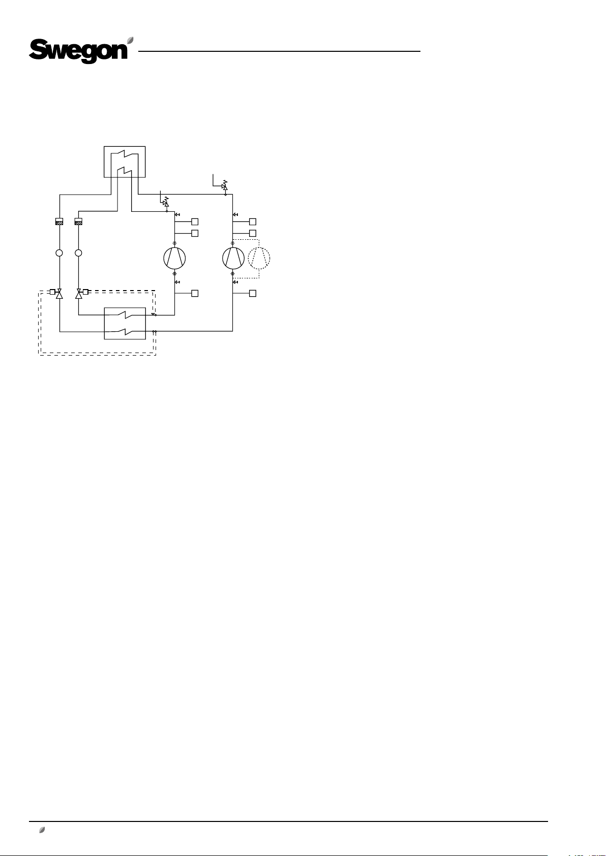
1.2 Basic function diagram
COND
VSH1
FD1FD2
IPL1IPL2
VET1VET2
EVAP
COND Condenser
VSH1 Overpressure protection
VSH2 Overpressure protection
B1-1 High pressure sensor
B2-1 Low pressure switch
B1-2 High pressure sensor
B2-2 Low pressure switch
BP1-2 High pressure switch, alarming
BP2-2 High pressure switch, alarming
M1 Compressor
M2 Compressor
M3 Compressor (size 80, cap. var. 3)
EVAP Evaporator
VET1 Expansion valve with thermostat
VET2 Expansion valve with thermostat
IPL1 Sight glass, cooling medium circuit 1
IPL2 Sight glass, cooling medium circuit 2
FD1 Filter dryer
FD2 Filter dryer
HP
HP
B1-1
M1 M2
LP
B2-1
VSH2
HP
HP
M3
LP
BP2-2BP1-2
B1-2
B2-2
The gaseous refrigerant is compressed by cooling compressors M1 and M2 and from there flows to condenser
COND, where it is cooled by the extract air and is condensed to liquid form.
The gaseous refrigerant flows through expansion valve
VET1 and VET2, where the pressure and the temperature
decrease.
From the expansion valves, the refrigerant advances to
evaporator EVAP, where the refrigerant evaporates and
cools down the outdoor air.
The evaporated refrigerant flows from evaporator EVAP
further to the suction side by the compressors to once
again be compressed.
Regulation
The cooling capacity is regulated in three binary steps by
having one or two compressors in operation.
COOL DX is controlled via a signal, 0 – 10 V.
Step 1: When cooling is needed, Compressor M1 is started.
Step 2: If more cooling is needed, Compressor M2 starts
and at the same time Compressor M1 stops. An adjustable time delay (a step duration of 250 seconds) ensures
that Compressor M2 will not start until Compressor M1 is
operating at full capacity.
Step 3: If even more cooling is needed, Compressor M1 is
restarted and is run at the same time as Compressor M2.
This third cooling step is also delayed by a preset time delay setting. In addition, the restarting time (300 seconds)
for Compressor M1 shall have expired.
If less cooling is needed and the compressors are subsequently switched out step-by-step, there will be no delay
between compressors. The restarting time (300 seconds)
for Compressor M1 shall have expired to enable it to start
again in Step 1 after it has been operated in Step 3.
If any compressor is stopped, the restarting time must
expire before a restart can take place. The restart time is
calculated from one start to the next start.
If the pressure in the cooling circuit becomes too low, or
if the pressure in the condenser circuit becomes too high,
the compressor is stopped.
When the restart time has expired, the compressors will try
to restart.
Function
There are two refrigerant circuits in the chiller. The circuits
are separated from one another.
Each circuit is equipped with its own finned condenser,
finned evaporator and compressor.
The two compressors are of different capacity, which
makes it possible to regulate the capacity in 3 steps.
4 www.swegon.com
If the pressure increases more, high pressure switches BP12 and BP2-2 will trip and stop the chiller.
Alarms are shown on the hand-held terminal, see separate
instructions for IC208CX control.
Pressure switches BP1-2 and BP2-2 can be manually reset
by pressing a button under each protective sock on the
upper side of the pressure switch. This can be done without removing the protective sock.
We reserve the right to alter specifications.
Page 5
GB.COOLDX.SI.G.190603
2 SAFETY INSTRUCTIONS
2.1 Safety Isolating Switch/Main Switch
The safety isolating switch is positioned on the inspection
side of the chiller.
The safety switch should not be used for start or stop of
the chiller.
Ensure that COOL DX is shut-off by turning off the chiller
via the display.
When this has been carried out, the current can be isolated with the safety switch. The safety switch must be
switched off in order to make it possible to open the
inspection door.
Important:
Always switch off the safety isolating switch before servicing the unit if not otherwise specified in the pertinent
instructions.
2.3 Electrical equipment
The machine’s electrical equipment is housed in a separate
cabinet inside one of the inspection doors.
2.4 Authorisation
Only authorized electricians shall be permitted to install
electrical wiring in the unit.
Only an accredited refrigeration company shall be permitted to modify or repair the refrigeration circuit.
Other service work in the unit should only be performed
by service personnel trained by Swegon.
2.5 Decals
The type number mark with type designation, serial number, refrigerant volume and more is affixed on the chiller’s
door.
Type designation: COOLDX-aa-F-c-d-e-f-g
SILVER C size
2.2 Risks
Warning
Before carrying out any work, make sure that the power
supply to the air handling unit has been switched off.
Warning
Under no circumstances may the refrigerant circuit be
opened by unauthorised personnel, since it contains gas
under high pressure.
Risk areas with refrigerant
Risk area for refrigerant is in principal inside the entire
chiller.
For handling when leakage, see section 7.2.
Refrigerant used is R 410A.
Capacity variant
Warning
The unit’s inspection door must not be opened when
the SILVER C air handling unit is operational. The door
can open and injure personnel. (The safety switch on the
COOL DX must be switched off in order to make it possible to open the inspection door of the chiller.)
We reserve the right to alter specifications.
www.swegon.com 5
Page 6
GB.COOLDX.SI.G.190603
3 INSTALLATION
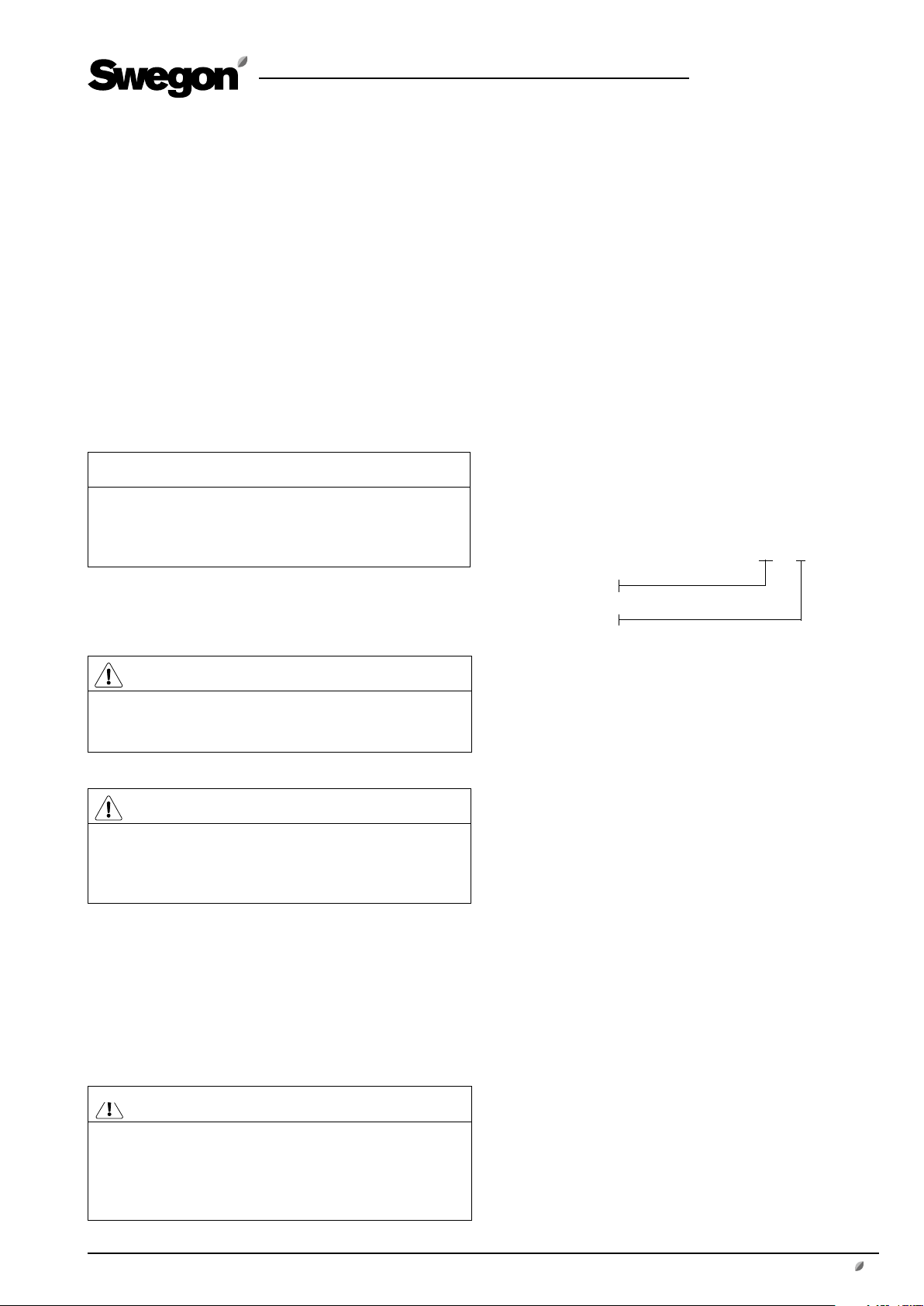
3.1 Unloading/site transport
Important:
All transport should take place with the chiller in horizontal position.
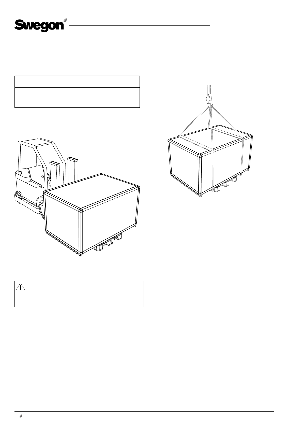
3.1.1 Handling with truck
3.1.2 Handling with crane
Place two line spreaders on top of the chiller and two on
the underside of the pallet or below the chiller and lift in
the pallet (or the chiller if the pallet is not to be included).
See the illustration.
Warning
High centre of gravity! Lift the chiller carefully.
3.2 Arrangement
Place the COOL DX at a suitable location.
Safety isolating switch/main switch must have the requisite space to serve according to applicable electrical regulations.
The unit can stand with the back against the wall, but to
facilitate any service of the rear compressor, a distance of
about 1 metre is recommended.
6 www.swegon.com
We reserve the right to alter specifications.
Page 7
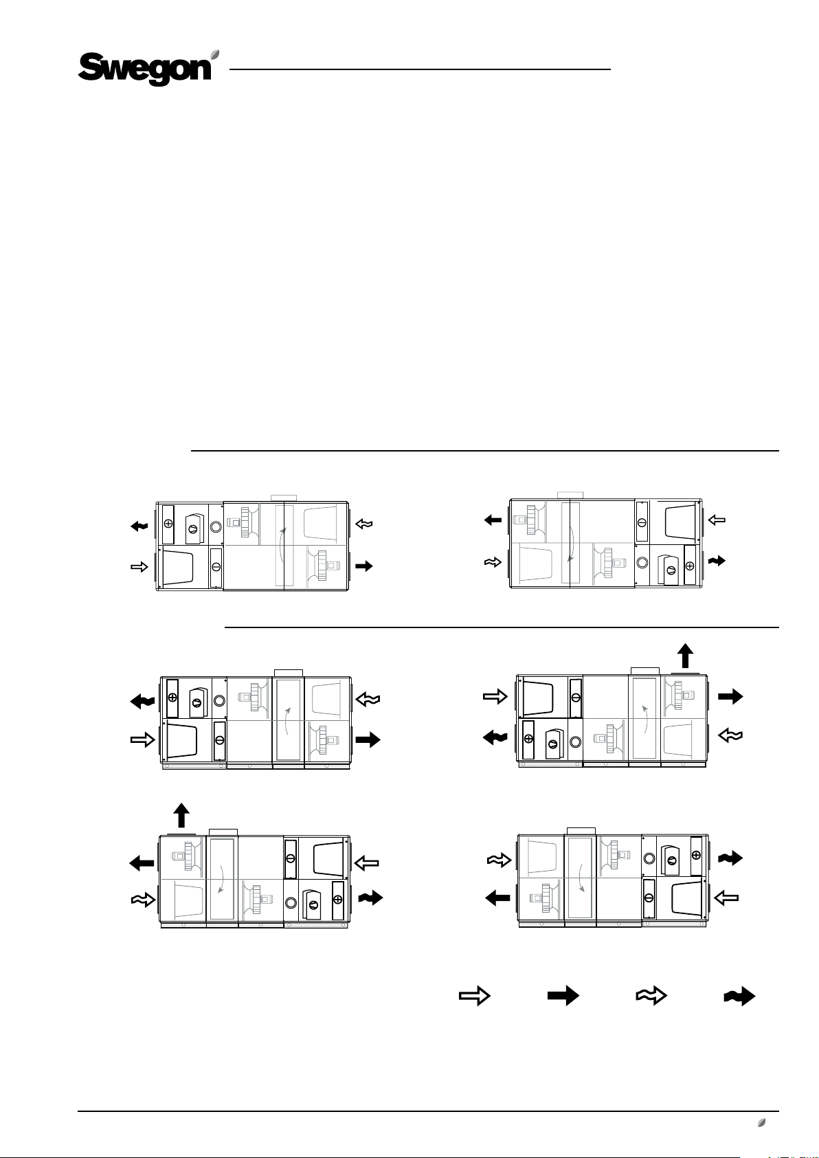
3.3 Basic Installation Diagram COOL DX
Locate the COOL DX chiller against the outdoor air and
exhaust air side of the SILVER C air handling unit. COOL
DX can also be installed as a stand-alone unit, if you order
a stand-alone COOL DX, select the variant with end connection panels.
The dimensions and capacity of the chiller COOL DX is
matched for connection to the SILVER C air handling unit
in sizes 008-080.
For a list of the capacity sizes of chillers matched to respective unit size,
see section 10. General technical data.
COOL DX 008
GB.COOLDX.SI.G.190603
Right-hand version Left-hand version
COOL DX 012-080
Cooling coil in lower level/SILVER C fan arrangement 1
Right-hand version
Cooling coil in upper level/SILVER C fan arrangement 2
Left-hand version
Cooling coil in upper level/SILVER C fan arrangement 1
We reserve the right to alter specifications.
Cooling coil in lower level/SILVER C fan arrangement 2
Outdoor air Supply air Extract air Exhaust air
www.swegon.com 7
Page 8

3.3.1 Height adjustment to the height of the SILVER C/water trap
COOL DX, size 008
In combination with the SILVER C RX 08
The SILVER C air handling unit can be mounted on base
beams, a stand or some other form of foundation. Base
beams and stands are available as accessories.
Appropriate base beams and stands are also available as
accessories for the COOL DX. The base beams/stands are
matched to one another in terms of height. The stands
also provide space for accommodating a possible water
trap in the lower level (right-hand unit version).
In combination with the SILVER C PX 008
The air handling unit is supplied with base beams. A set of
legs (accesssory) can be mounted in the base beams.
Appropriate base beams and set of legs are also available
as accessories for the COOL DX. The base beams/sets of
legs are matched to one another in terms of height. The
sets of legs also provide space for accommodating a possible water trap in the lower level (right-hand unit version).
GB.COOLDX.SI.G.190603
COOL DX, sizes 012-080
The SILVER C air handling unit and the COOL DX cooling
unit are supplied with a 100 mm high base beam.
Applicable to a cooling coil in the lower level:
If a water trap (accessory) is fitted, the SILVER C air handling unit and the cooling unit must be raised at least 50
mm to provide space for the water trap. Adjustable support feet (accessories) can be appropriately fitted to the
base beams for this purpose.
8 www.swegon.com
We reserve the right to alter specifications.
Page 9

3.3.2 Connection to SILVER C air handling unit,
COOL DX, sizes 008-012
The sealing strips are factory-fitted to the unit.
The chiller is connected directly to the air handling unit by
means of the supplied bolts + pre-fitted rivets nut and 2
expansion locking devices, see the figure.
Secure the chiller to the air handling unit from inside the
unit via the inspection door. It may be necessary to remove
the fan assembly or filter cassettes in order to reach the
expansion-type locking device.
Expansion-type locking device
GB.COOLDX.SI.G.190603
COOL DX Chiller
In this case, fastening is done with the bolts and
pre-fitted rivet nuts.
We reserve the right to alter specifications.
www.swegon.com 9
Page 10

GB.COOLDX.SI.G.190603
3.3.3 Connection to SILVER C air handling unit,
COOL DX, sizes 020-040
The sealing strips are factory-fitted to the unit.
Dock the chiller directly to the SILVER C air handling unit
by means of the supplied bolts (4 bolts) + pre-fitted rivet
nuts.
To secure accessories to the rear edge
Alternative 1, External installation
Illustration 1
The SILVER C air handling unit, rear
Remove the cover and insulation. Secure the chiller to the SILVER C air handling unit
with the bolts supplied and pre-fitted rivet nuts. Refit the blanking plate and the
insulation.
Option 1
If there is sufficient space for working from the rear of the
air handling unit, the simplest way to secure the chiller at
the rear edge of the SILVER C air handling unit is by externally jointing it, see Illustration 1.
Secure the chiller to the front edge of the SILVER C air
handling unit within the unit via the inspection cover, see
Illustration 3.
Option 2
The chiller is secured to the back edge of the SILVER C
air handling unit within the casing, see Illustration 2. This
requires removal of the fan assembly and filter cassettes.
Secure the chiller to the front edge of the SILVER C air
handling unit within the unit via the inspection cover, see
Illustration 3.
COOL DX chiller, rear
Alternative 2, Internal installation
Illustration 2
To secure accessories to the front edge
Illustration 3
COOL DX Chiller
In this case, fastening is done with the bolts supplied and pre-fitted rivet nuts in
predrilled holes.
COOL DX Chiller
In this case, fastening is done with the bolts supplied and pre-fitted rivet nuts in
predrilled holes.
10 www.swegon.com
We reserve the right to alter specifications.
Page 11

3.3.4 Connection to SILVER C air handling unit,
COOL DX, sizes 060-080
The sealing strips are factory-fitted to the unit.
Dock the chiller directly to the SILVER C air handling unit
by means of the supplied bolts (4 bolts) + pre-fitted rivet
nuts, see the illustration.
You may need to remove the filter cassettes.
COOL DX Chiller
In this case, fastening is done with the bolts supplied and pre-fitted rivet nuts in
predrilled holes.
GB.COOLDX.SI.G.190603
3.3.5 Stand-alone COOL DX
The variant with end connection panel should be selected.
Ducts connect between the SILVER C air handling unit and
COOL DX chiller, see section 3.3 Basic Installation Diagram
COOL DX.
3.3.6 Supply air filter
The supply air filter in the SILVER C air handling unit should
be dismantled and moved to the COOL DX unit.
We reserve the right to alter specifications.
www.swegon.com 11
Page 12

4 POWER CONNECTION
The cross sectional dimension of the power supply cable
should take into consideration the ambient temperature
and way the cable is run.
Important:
Installation must be carried out by a authorised electrician.
4.1 Power connection
Incoming power supply
Sizes 008-020, all capacity variants, and size 030, capacity
variant 1:
5-core system, 400 V ±10%.
GB.COOLDX.SI.G.190603
Size 030, capacity variants 2 and 3 and size 040-080 all
capacity variants:
4-core system, 400 V ±10%.
COOL DX, sizes 008-040, 060-1/2
Open the inspection door in front of the electrical equipment cubicle.
Open the inspection door of the electrical equipment
cubicle.
Pull the incoming cable for power supply through predrilled hole in the cover panel of the chiller (supplied cable
gland is mounted), through the space for compressors
and through the cable gland of the electrical equipment
cubicle. Locate the cable in a safe way. Make sure that the
cable does not touch the compressors or other components, since surfaces could be hot or vibrate.
Connect the incoming power supply to the safety switch
situated in the electrical equipment cubicle, see the illustration. The wiring terminal for incoming earth is situated
right next to the safety switch.
See section 10, Technical data.
Sizes 060–3, 080
Remove the cover on the external safety switch.
Safety switch block.
Supply is connected here
Connect the incoming power supply to the safety switch,
see the illustration. The wiring terminal for incoming earth
is situated right next to the safety switch.
See section 10, Technical data.
4.2 Connection signal 0-10 V
Terminals 103 and 104 are connected to give a signal,
0-10 V. For more information, also see the electrical wiring
diagram supplied separately.
12 www.swegon.com
Factory-fitted
cables
We reserve the right to alter specifications.
Page 13

GB.COOLDX.SI.G.190603
5 COMMISSIONING
5.1 Preparations
5.1.1 Before initial start up
• The power supply should be connected.
• Terminals 105 and 106 in COOL DX electrical cabi-
net must be connected (closed switch), otherwise
the cooling machine will not start despite the signal
0 – 10 V, and no compressors are activated. (These
terminals can be used to connect an external thermostat to activate/deactivate signal 0 – 10 V for a specific
temperature).
• Terminals 103 and 104 shall be connected to give a
signal, 0-10 V.
A free contact for a general alarm is located on terminals
100, 101 and 102.
5.1.2 Control functions
Silver Cool DX is equipped with two controls:
• IC208CX Dixell, hardware version 7.3 or 4.2
• Siemens (model: 12/24 RC 6ED1052-1MD08-0BA0)
Signal 0-10 V is received by the Siemens control which
converts it to digital output signals (see below) and forwards these to control IC208CX.
Control IC208CX is set at the factory to moto-condenser
mode and starts or stops the compressors via the digital
output signals from the Siemens control. All control and
safety functions for the refrigerant circuit are regulated by
control IC208CX.
For conversion of the signal, 0 – 10 V to digital output
signals, see below.
5.1.3 Pressure sensor
The chiller has two in-service pressure switches in each
cooling circuit, one for low pressure and one for high pressure.
If the operating pressure, in any of the circuits, exceeds
or drops below a limit value, the relevant compressor is
switched off. See separate instructions for IC208CX control for further information.
The compressor is permitted to restart when the restart
delay has expired.
Pressure sensor settings:
Value Setting Factory
range settings
Compressor 1
Low pressure limitation 1-10 bar 4.5 bar
High pressure limitation 25-50 bar 39.0 bar
High pressure alarm limit 25-50 bar 42 bar
Compressor 2
Low pressure alarm limit 1-10 bar 4.5 bar
High pressure limitation 25-50 bar 39.0 bar
High pressure alarm limit 25-50 bar 42 bar
When the 0-10 V increases:
• Point 1: Q1 and Q2 = OFF
• Point 2: signal increases to above 1 V, then Q1= ON
and Q2 = OFF
• Point 3: signal increases to above 4 V, then Q1= OFF
and Q2 = ON
• Point 4: signal increases to above 7 V, then Q1= ON
and Q2 = ON
When the 0-10 V decreases:
• Point 4: signal decreases to below 7 V, then Q1= OFF
and Q2 = ON
• Point 3: signal decreases to below 4 V, then Q1= ON
and Q2 = OFF
• Point 2: signal decreases to below 1 V, then Q1= ON
and Q2 = OFF
• Point 1: Q1 stops when the signal reaches 0 V
Q1 and Q2 are the digital output signals that are sent to
control IC208CX to activate compressor 1 and 2.
Q1= compressor with lower cooling capacity
Q2 = compressor with higher cooling capacity
For more information about control and safety functions,
see separate instructions for IC208CX control.
We reserve the right to alter specifications.
www.swegon.com 13
Page 14

GB.COOLDX.SI.G.190603
5.1.4 Phase sequence monitor
The COOL DX unit is equipped with phase sequence
guard for compressors (not size 008 capacity variant 1).
The phase sequence monitor is installed in the electrical
cabinet.
Phase sequence monitor
The phase sequence is correct when LED 1 is lit.
The voltage is connected when LED 2 is lit.
PSC
DPA51 3-Phase monitoring relay
1
1
2
5.1.5 Measure whether the phase-sequence is
wrong
6 ALARMS
For an alarm description, see the separate instructions for
IC208CX control.
Warning
May only be performed by authorised or trained service
personnel.
• Stop the COOL DX by selecting SHUT OFF in the
menu SETTINGS.
• Set the safety switch to position OFF on the COOL
DX.
• Switch the power supply to COOL DX.
Important:
Check that the incoming power supply to the COOL DX
is isolated by measuring.
• Transpose the two phase wires on the incoming
power supply cable in order to
obtain correct phase sequence (direction of rotation).
• Switch on the power supply to COOL DX.
• Set the safety switch to ON.
• Start COOL DX as described in the section dealing
with starting up, see Section 5.1.2.
14 www.swegon.com
We reserve the right to alter specifications.
Page 15

GB.COOLDX.SI.G.190603
7 MAINTENANCE
7.1 Cleaning
If needed, clean the inside cleaning of the unit by vacuum
cleaning and wiping surfaces with a damp cloth.
Inspections should be performed twice a year.
7.2 Handling of refrigerant
The refrigerant used is R 410A.
The refrigerant circuit is completely charged when the unit
is delivered.
Warning
Under no circumstances may the refrigerant circuit be
opened by unauthorised personnel, since it contains
gas under high pressure. Only an accredited refrigeration company shall be permitted to modify or repair the
refrigeration circuit.
The COOL DX is equipped with a safety valve to prevent
excessively high pressure in the system caused by e.g. a
fire.
Important:
Contact Swegon Service in the event of leakage of
refrigerant.
Warning
Important:
Filling of refrigerant must be performed in accordance
with the recommendations of the refrigerant manufacturer.
Avoid direct skin contact with refrigerant and lubricant.
Use tightly sitting protective glasses, protective gloves
and covering work clothes.
Arrange ventilation/point extraction.
In the event of eye contact
rinse the eyes using an eye-wash shower (or with lukewarm water) for 20 minutes. seek a doctor.
In the event of contact with skin
carefully wash with soap and lukewarm water.
In the event of frostbite
seek a doctor.
7.3 Leakage tracing interval/
Obligation to report
Must be carried out according to the F-Gas Regulation
EU/517/2014 and associated local legislation.
7.4 Service
Only service personnel trained by Swegon should be permitted to modify the chiller.
If refrigerant is exposed to fire or in some other way
becomes superheated in the atmosphere, poisonous
gases can form.
We reserve the right to alter specifications.
www.swegon.com 15
Page 16

8 TROUBLE SHOOTING AND
LEAKAGE TRACING
8.1 Troubleshooting Schedule
Symptoms Possible cause Action
Compressor is not operating The voltage has been isolated.
Incorrect phase sequence.
The compressor safety circuit has been broken.
Defective compressor.
Too low cooling capacity The voltage has been isolated.
Incorrect phase sequence.
No air flow or too low air flow across the evaporator.
Thermostat/control equipment incorrectly set or defective.
The compressor switches off
because the low pressure sensor
has measured an excessively low
value.
The compressor switches off
because the high pressure sensor
has measured an excessively high
value.
Significant freezing on the
evaporator.
Inadequate refrigerant.
No air flow or too low air flow across the evaporator.
The expansion valve is defective.
The low pressure switch is defective.
No air flow or too low air flow across the condenser.
Excessively high exhaust air temperature.
The high pressure sensor is defective.
The expansion valve is defective or incorrectly set.
No air flow or too low air flow across the evaporator.
Check the operating/safety switch. Check the condition of the fuses.
Check and change the phase sequence.
Check, reset if needed.
Replace the compressor.
Check the operating/safety switch. Check the condition of the fuses.
Check and change the phase sequence.
Check the air flow.
Adjust the setting or replace faulty components.
The cooling system is leaking. Tighten the leak and
charge with refrigerant.
Check the air flow.
Check, replace.
Check, replace.
Check the air flow.
Check the exhaust air temperature.
Check, replace.
Check. Replace or adjust setting.
Check the air flow.
GB.COOLDX.SI.G.190603
8.2 Leakage Tracing
Leakage tracing should be carried out at least once per
year as a precaution. The leakage tracing inspection must
be documented.
If the cooling system is leaking, this will become apparent
firstly by impaired cooling performance, or if the leakage is
substantial, when the chiller does not operate at all.
If you suspect that the cooling system is leaking refrigerant, check the level of refrigerant in the sight glass located
on the liquid line of the chiller.
If you see continuous and a substantial amount of bubbling in the sight glass and the chiller operates at appreciably lower capacity than normal, the system is probably
leaking. One or several bubbles appearing when the chiller
is started up, operation at reduced capacity or normal
operation need not necessarily indicate a refrigerant deficiency.
If it is bubbling in the sight glass and the chiller operates at
appreciably lower capacity, call for qualified service help.
NOTE! Maintenance work in the refrigerant system is permitted to be carried out only by an accredited inspectorate
(a company with requisite authorisation).
16 www.swegon.com
We reserve the right to alter specifications.
Page 17

9 DIMENSIONS
5050
16
K
1)
1)
16
1)
M
1)
5050 K
454521 K
1)
M
1)
COOL DX 008
GB.COOLDX.SI.G.190603
Base beams are accessories.
1)
End connection panel, optional.
COOL DX 012
M
1)
End connection panel, optional.
Size L B H K M Duct connection
008 900 995 1085 749 709 Ø 400
2)
For the locations of the duct connections, see the corresponding
SILVER C air handling unit
Size L B H K M Duct connection
012 900 1199 1395 953 709 Ø 500
2)
For the locations of the duct connections, see the corresponding
SILVER C air handling unit
2)
2)
COOL DX 020, 030, 040, 060, 080
Size L B H K M Duct connection
020
030
040
060
080
2)
For the locations of the duct connections, see the corresponding
900
900
1100
1100
1100
1400
1600
1990
2318
2637
1551
1811
2159
2288
2640
1154
1354
1744
2072
2395
709
709
884
884
884
1000 x 400
1200 x 500
1400 x 600
1600 x 800
1800 x 1000
SILVER C air handling unit
1)
End connection panel, optional.
2)
We reserve the right to alter specifications.
www.swegon.com 17
Page 18

10 GENERAL TECHNICAL DATA
Cooling system COOL DX
GB.COOLDX.SI.G.190603
Refrigerant
(kg)
Nom.
COOL
DX
Size
008 1 0.55 0.22 9.8 2.39 1,20 1.30 3-phase+N, 400 V ±10%, 16 A 194 8
012 1 0.85 0.35 15.4 3.95 1,50 1.70 3-phase+N, 400 V ±10%, 20 A 260 10
020 1 1.1 0.45 15.4 4.06 1,20 1,50 3-phase+N, 400 V ±10%, 25 A 243 11
030 1 1.8 0.7 25,0 6.33 1,80 2.00 3-phase+N, 400 V ±10%, 32 A 322 17
040 1 2.9 1.1 38.6 8.40 3.30 4.00 3-phase, 400 V ±10%, 25 A 468 22
060 1
080 1
Cap.
flow
var-
(m
iant
2 0.70 0.3 13.9 4.33 1,20 1.30 3-phase+N, 400 V ±10%, 20 A 215 8
2 1.05 0.4 20.9 6.53 1,50 1.70 3-phase+N, 400 V ±10%, 25 A 287 10
2 1.3 0.5 23.3 5.73 2,50 2,80 3-phase+N, 400 V ±10%, 25 A 283 11
3 1.6 0.6 31.0 9.15 2,10 2.40 3-phase+N, 400 V ±10%, 40 A 314 11
2 2.0 0.8 35.8 9.34 3.00 3,20 3-phase, 400 V ±10%, 25 A 374 17
3 2.4 1.0 46.2 13.5 2.90 3.30 3-phase, 400 V ±10%, 40 A 414 17
2 3.1 1.3 48.4 12.3 3.30 4.50 3-phase, 400 V ±10%, 40 A 476 22
3 3.6 1,5 67.0 17.5 5.50 4.50 3-phase, 400 V ±10%, 50 A 529 22
2
3
2
3
air
3
3.9
4.1
5,0
5.2
6.0
7.0
/s)
Min
air
flow
(m
1,5
1.6
2.0
2.0
2.4
2.8
3
/s)
Nom.
cooling
1)
cap.
(kW)
56.2
66.7
97.5
67.0
96.5
134.0
Nom.
Power
required
(kW)
11.8
17.1
26.3
13.3
24.8
36.4
Circuit 1Circuit
2
4.50
5,00
6.00
6,60
6,50
9.00
5.50
5.20
7,50
7,30
9.00
11.50
Power
supply
3-phase, 400 V ±10%, 40 A
3-phase, 400 V ±10%, 50 A
3-phase, 400 V ±10%, 80 A
3-phase, 400 V ±10%, 50 A
3-phase, 400 V ±10%, 80 A
3-phase, 400 V ±10%, 100 A
Weight
excl. end
conn.
panel
(kg)
708
779
852
852
979
1035
Weight
of each
end conn.
panel, if
required
(kg)
31
31
31
38
38
38
2)
1)
For an outdoor temperature of 26°C, 50% RH (capacity variant 1), 27°C, 50% RH (capacity variant 2) or 28°C, 50% RH (capacity variant 3), and
an extract air temperature of 26°C.
2)
The first weight applies to a small end connection panel; the second weight applies to a large end connection panel. COOL DX can be supplied
completely without end connection panels or with a maximum of 2 small and two large end connection panels depending on the variant selected.
Sizing
There are many factors that influence what size of chiller is
required.
COOL DX is designed to handle very different prerequisites.
For correct sizing we refer to our ProUnit air handling unit
selection program.
18 www.swegon.com
We reserve the right to alter specifications.
Page 19

11 INTERNAL WIRING DIAGRAM
2R
L3
11.1 COOL DX, size 08, capacity variant 1
1
5
2
-RM2
M2.2
RM2.1
-CS2
-CM2
GB.COOLDX.SI.G.190603
5
6
3
4
br
1
2
blue
/3.7
-QF3
-QF2
/3.3
/3.2
-KM2
1
2
-RM1
RM1.1
RM1.
-CS1
-CM1
5
6
3
4
bl
1
2
blue
/3.6
-KM1
/2.0
10
10
21
-KM2
10
21
-KM1
4G1,5 mm²
-W2
5
4G1,5 mm²
-W1
04
22
-X1
/3.7
03
22
-X1
/3.6
S
bl
RC
M
br
C2 R2 S2
-X1
C1 R1 S1
-X1
1~
blue
S
br
RC
bl
blue
-PE
-M2
M
-M1
-PE:2
1~
-PE
-PE:1
/2.0
00
00
-X1
00
-R1 -R2
-X1
/2.31/2.3
0
-QF01
7
-QF1
grey
black
brown
blue
-Q
N
L2
L1
3
230V
2
-TC1
24V 230V
LINIE KUNDENS. GESCHUEZT
LIGNE PROTEGEE PAR LE CLIENT
LINE PROTECTION BY CUSTOMER
LINEA PROTETTA A CURA DEL CLIENTE
0
4
-PE:3
We reserve the right to alter specifications.
10
1
-QF02
Cx = Condenser
QFx = Fuse
KMx = Contactor
Q = Load separator
Rx = Crankcase heater
www.swegon.com 19
Page 20

GB.COOLDX.SI.G.190603
L3
11.2 The COOL DX size 08, capacity variants 2, size 12 and 20, all capacity
variants and size 30, capacity variant 1
/3.332/3.3
L3
-L3:
L2
-L2:
L1
L1:
-PSC
brown
grey
black
/3.3
13
14
5
6
I>
3
4
I>
1
2
I>
grey
black
brown
5
6
3
4
1
2
/3.7
-KM2
-QM2
1
2
-RM1
RM1.2
RM1.1
29
14
11
WVU
grey
M
black
-W2
brown
3~
PE
-PE:2
-M2
5
grey
-CS1
-CM1
5
6
3
4
black
1
2
blueblue
/3.6
-QF2
/3.2
-KM1
/2.0
10
10
21
-KM2
10
21
-KM1
C1 R1 S1
-X1
04
22
-X1
/3.7
03
22
-X1
/3.6
S
black
RC
M
brown
1~
-W1
-PE
-M1
-PE:1
/2.0
/2.31/2.3
00
0
00
-X1
00
-R1 -R2
-X1
-QF01
7
-QF1
brown
black
blue
-Q
N
L2
L1
3
230V
2
-TC1
24V 230V
-PE:3
0
4
10
1
-QF02
20 www.swegon.com
LINIE KUNDENS. GESCHUEZT
LIGNE PROTEGEE PAR LE CLIENT
LINE PROTECTION BY CUSTOMER
LINEA PROTETTA A CURA DEL CLIENTE
LIMITE FORNITURA
Cx = Condenser
QFx = Fuse
KMx = Contactor
PSC = Control system for phase sequence
Qmx = Motor protection
Q = Load separator
Rx = Crankcase heater
We reserve the right to alter specifications.
Page 21

GB.COOLDX.SI.G.190603
L3
13
14
11.3 COOL DX, size 30, capacity variants 2 and 3, size 40, all capacity variants and size 60,
capacity variants 1 and 2, size 80, capacity variant 1
/3.3
5
6
I>
3
4
I>
1
2
I>
-QM2
/3.2
13
14
5
6
I>
3
4
I>
1
2
I>
-QM1
grey
black
brown
grey
black
brown
5
6
3
4
1
2
-W2
/3.7
-KM2
5
6
3
4
1
2
-W1
/3.6
-KM1
/3.332/3.3
L3
-L3:
L2
-L2:
L1
L1:
29
14
11
grey
black
brown
grey
black
brown
WVU
M
3~
PE
-PE:2
-M2
WVU
M
3~
PE
-PE:1
-M1
grey
-PSC
/2.0
10
10
21
-KM2
grey
black
brown
10
21
-KM1
black
brown
5
6
I>
3
4
I>
1
2
I>
3
400-415V
2
-TC1
-Q
L2
L1
-QF1
LINIE KUNDENS. GESCHUEZT
LIGNE PROTEGEE PAR LE CLIENT
LINE PROTECTION BY CUSTOMER
LINEA PROTETTA A CURA DEL CLIENTE
24V 230V
-PE:3
7
0
4
04
22
-X1
/3.7
03
22
-X1
/3.6
-R1 -R2
-QF01
10
-QF02
/2.0
/2.31/2.3
00
0
00
-X1
00
-X1
1
Cx = Condenser
QFx = Fuse
KMx = Contactor
PSC = Control system for phase sequence
Qmx = Motor protection
Q = Load separator
Rx = Crankcase heater
We reserve the right to alter specifications.
www.swegon.com 21
Page 22

11.4 COOL DX size 60, capacity variant 3 to size 80, capacity variant 2
L3
13
14
M2M1 /3.7
/3.3
5
5
6
I>
3
4
I>
1
2
I>
-QM2
/3.2
13
14
5
6
I>
3
4
I>
1
2
I>
grey
black
brown
grey
black
brown
6
3
4
1
2
-W2
/3.7
-KM2
5
6
3
4
1
2
-W1
/3.6
-KM1
-QM1
/3.332/3.3
L3
-L3:
L2
-L2:
L1
L1:
29
14
11
grey
black
brown
grey
black
brown
WVU
M
3~
PE
-PE:2
-M2
WVU
M
3~
PE
-PE:1
-M1
GB.COOLDX.SI.G.190603
grey
-PSC
/2.0
10
10
L
N
-X1
/2.0
00
00
-X1
/2.31/2.3
0
-FTM2
10
21
-KM2
grey
black
brown
10
21
-KM1
black
brown
5
6
I>
3
4
I>
1
2
I>
3
400-415V
2
-TC1
24V 230V
-PE:3
7
0
4
-QF1
04
22
-X1
/3.7
03
22
-X1
/3.6
-R1 -R2
-QF01
10
-QF02
00
-X1
00
-X1
1
L2
L1
22 www.swegon.com
-Q
LINIE KUNDENS. GESCHUEZT
LIGNE PROTEGEE PAR LE CLIENT
LINE PROTECTION BY CUSTOMER
LINEA PROTETTA A CURA DEL CLIENTE
Cx = Condenser
QFx = Fuse
KMx = Contactor
PSC = Control system for phase sequence
Qmx = Motor protection
Q = Load separator
Rx = Crankcase heater
We reserve the right to alter specifications.
Page 23

12 Commissioning Record
Company
Our reference
Client Date SO No.
Plant Project/Air handling unit Subject no:
Plant address Type/size
GB.COOLDX.SI.G.190603
Installation/connections
Inspection measure
Installation according to instructions
Condensate drain correctly connected, water trap filled with water
The supply air filter in the SILVER C air handling unit has been moved
to the COOL DX unit.
Electrical connections installed according to instructions
Control cable from COOL DX connected according to instructions
Appr./Exec.
Remarks
We reserve the right to alter specifications.
www.swegon.com 23
Page 24

GB.COOLDX.SI.G.190603
Checks COOL DX, size Factory-preset value Checked value
Safety switch, Compressor 1 08-1 D10
Safety switch, compressor 2 D13
Safety switch, Compressor 1
08-2 D10
Protective motor switch, Compr. 2 8.5 A
12-1 D10
8.5 A
12-2 D16
14.4 A
20-1 D10
13.0 A
20-2 D16
14.4 A
20-3 D16
18.0 A
30-1 D16
14.4 A
Protective motor switch, Compressor 1
Protective motor switch, compressor 2
30-2 13.0 A
18.0 A
30-3 14.4 A
21.0 A
40-1 13.0 A
18.0 A
40-2 14.4 A
21.0 A
40-3 18.0 A
27.0 A
60-1 14.4 A
21.0 A
60-2 18.0 A
27.0 A
60-3 21.0 A
45.0 A
80-1 14.4 A
27.0 A
80-2 21.0 A
45.0 A
80-3 27.0 A
33.0 A
Protective motor switch, Compr. 3 33.0 A
24 www.swegon.com
We reserve the right to alter specifications.
 Loading...