

Page 1
CONDUCTOR W4
Installation instruction for W4.1 and W4.2
Controller
4
3
5
2
8
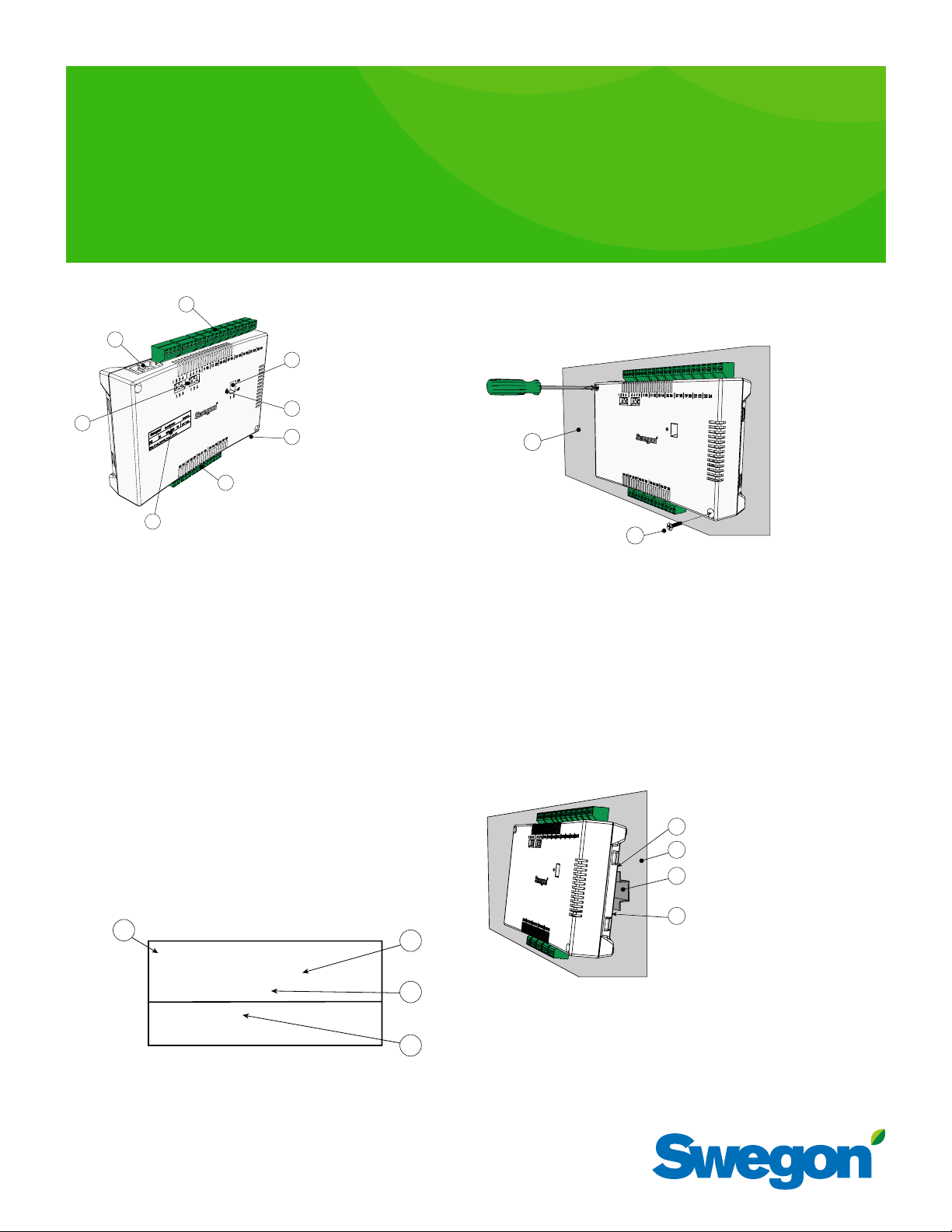
Figure 1. Overview of the Controller.
Pos 1. Product marking.
Pos 2. Termination resistance.
1 = The unit is the last node in the network
2 = The unit is the first node in the network
3 = The unit is situated between the first and last nodes
Pos 3. Modular Contact / ModBUS RTU units (pressure sensor and room unit)
Pos 4. Inputs: Wiring terminals for the connection of sensors.
Pos 5. DIP switch for ModBUS RTU.
1 (=on) boosts the controller to Modbus address 1
2 (=on) access to Modbus register via BMS system
(requires a restart of the controller)
Pos 6. LED, indicates the status of the controller.
Pos 7. Input and output for signal to external relay.
Pos 8. Outputs: Wiring terminals for the connection of valve and
damper actuators.
1
Product Identification Label
1
Conductor RE W4
Modbus Adress 2
Artnr: 942334001
RF id: 00350
IIIIIIIIIIIIIIIIIIIIIIIIIIIIIII
Figure 2. Product identification label on the controller.
Pos 1. Name of the product.
Pos 2. ModBus RTU address default from factory.
Pos 3. Part number.
Pos 4. Controller ID number.
6
7
2
3
4
To be installed above a false ceiling
If a DIN rail is NOT available pre-mounted or is not available, the controller can be appropriately mounted above the false ceiling (not on the
module).
1
2
Figure 4. To mount the controller.
Pos 1. Supporting surface, NOT for the comfort module or climate beam.
Pos 2. Screws.
a. Secure the controller by means of screws in the upper left-hand and the
lower right-hand corners. Use screws suitable for the supporting surface.
To mount the controller.
Mounting on a DIN rail
1
2
3
4
Figure 3. To mount the controller.
Pos 1. Plastic hooks
Pos 2. Supporting surface
Pos 3. DIN rail
Pos 4. Snap-on fastener.
Page 2
CONDUCTOR W4
W4.1 (Hotel/Office)
6
7
5
1
4
3
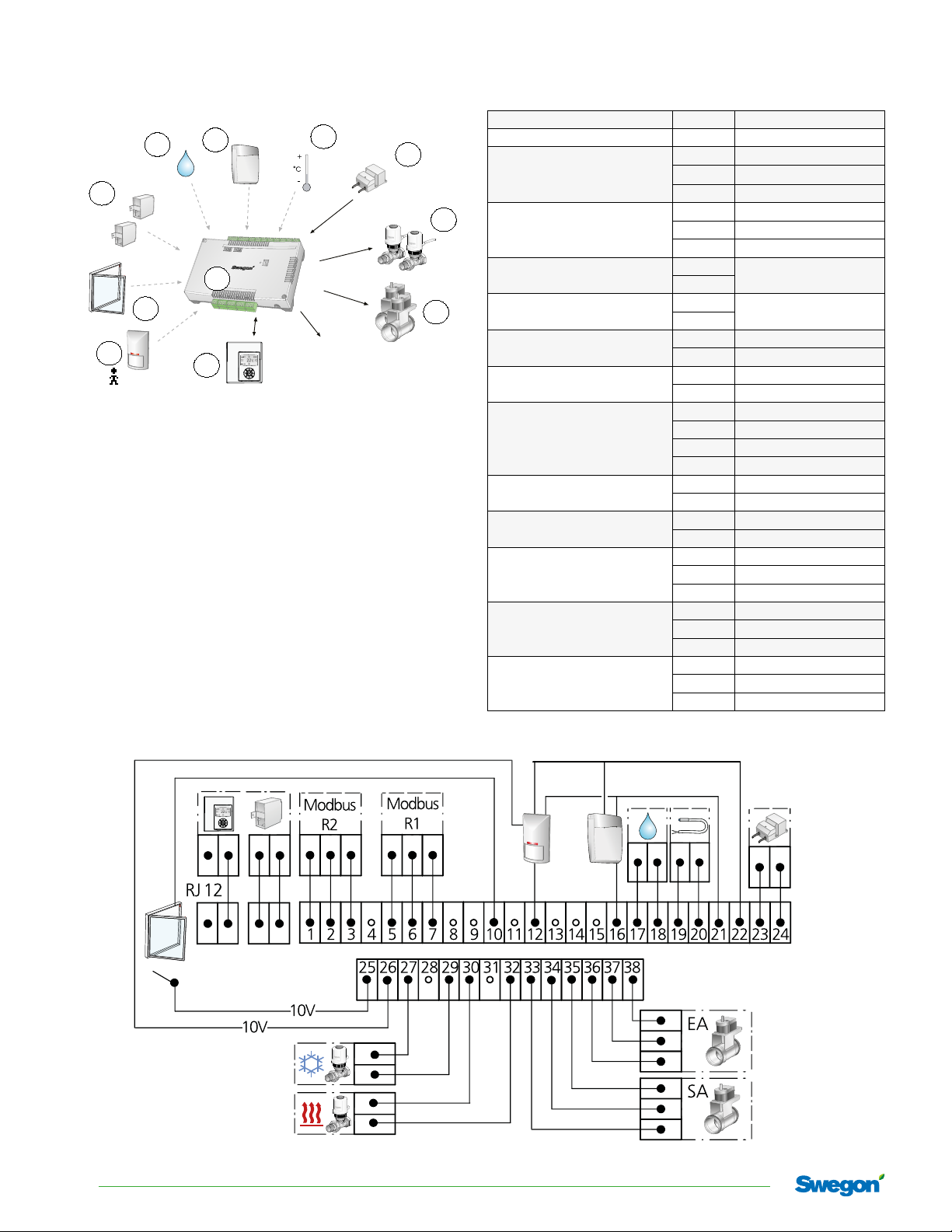
Figure 5. CONDUCTOR W4.1: Integral Components
1
Controller
2
Room unit
3
Presence detector
4
Window contact
5
Pressure sensor
6
Condensation sensor
7
CO2-sensor
8
External temp. sensor
9
Transformer
10
Valve actuator
11
Ventilation damper
incl. damper actuator
• Connect the presence sensor, check application parameter P_1910
• Connect the window contact, check application parameter P_1909
• Connect the pressure sensor to the Modular contact.
Set the address on sensor: SA1 = 3, EA = 4
• Check application parameters P_1929, P_1930 and P_1931. (P_1930
allways 0 in appl W4.1)
2
Conductor RE
Conductor RU
DETECT Occupancy
SYST PS
SYST CG
DETECT Quality
CONDUCTOR T-TG
SYST TS-1
ACTUATOR b 24V NC
CRTc -aaa-2
(aaa = dimension)
8
9
10
11
Monitoring
system via ModBus
Room unit RJ12 Modular contact
Pressure sensor RJ12 Modular contact
1 Data (B)
MODBUS RS2
MO DBUS RS1
Condensation sensor
Temperature sensor
Transformer
Window contact
Presence detector
Valve actuator, cooling
Valve actuator, heating
Damper, supply air (SA)
Damper, extract air ( EA)
-sensor
CO
2
2 Data (A)
3 Earth
5 Data (B)
6 Data (A)
7 Earth
17
Resistance
18
19
KTY
20
23 + 24V AC
24 -G0
25
10V
10 10V
26 10V
12 0-10V
21 +24V AC
22 -G0
27 -G0
29 +24V
30 -G0
32 +24V
33 -G0
34 0-10V
35 +24V
36 -G0
37 0 -10V
38 +24V
16 0-10V Signal
21 +24V AC
22 -G0
Figure 6. Wiring diagram,
CONDUCTOR W4.1
2
Swegon reserves the right to alter specications. 15-03-2017
Page 3
W4.2 (Conference)
6
7
5
1
4
3
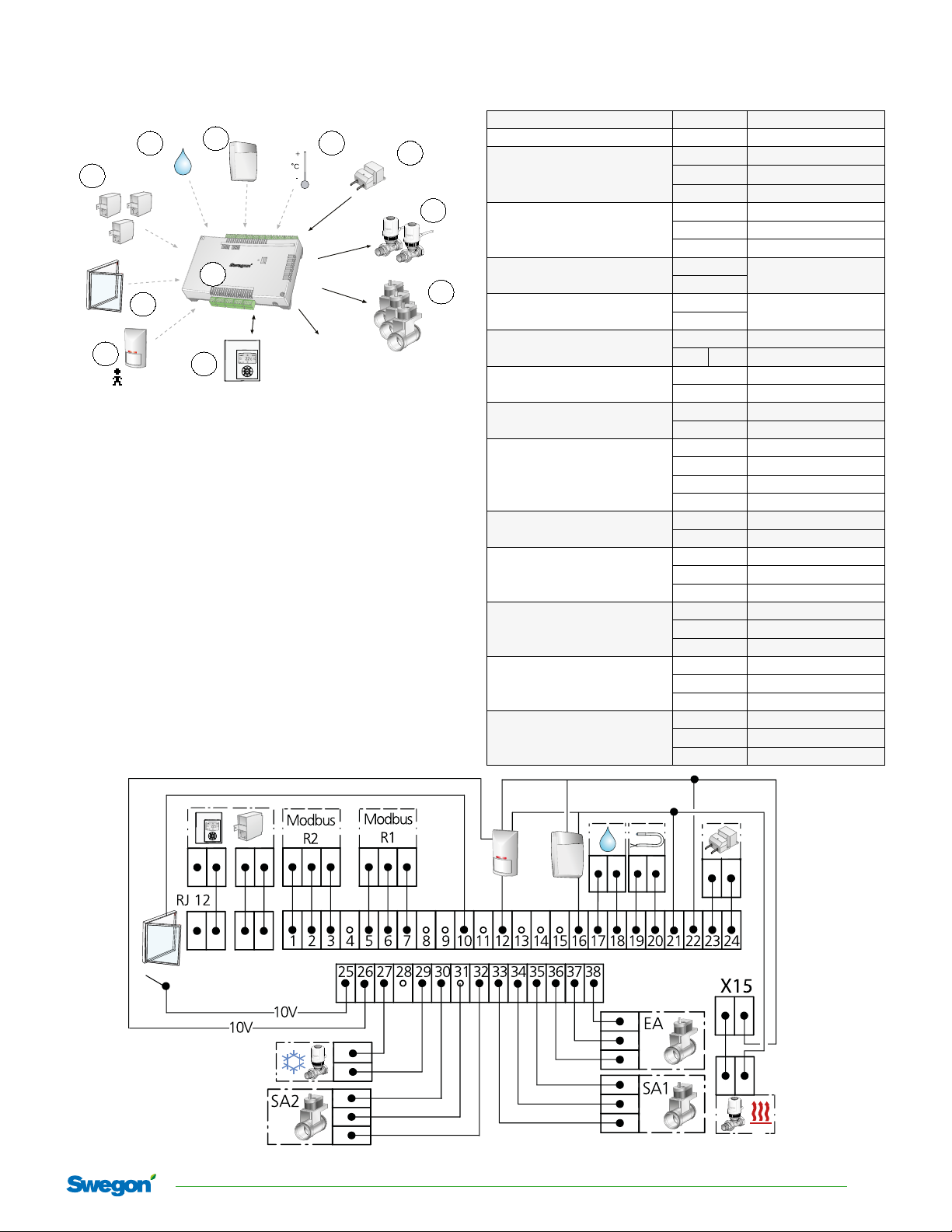
Figure 7. CONDUCTOR W4.2: Integral Components
1
Controller
2
Room unit
3
Presence detector
4
Window contact
5
Pressure sensor
6
Condensation sensor
7
CO2-sensor
8
External temp. sensor
9
Transformer
10
Valve actuator
11
Ventilation damper
incl. damper actuator
• Connect the presence sensor, check application parameter P_1910
• Connect the window contact, check application parameter P_1909
• Connect the pressure sensor to the Modular contact.
Set the address on sensor: SA1 = 3, SA2 = 6, EA = 4
• Check application parameters P_1929, P_1930 and P_1931.
2
Conductor RE
Conductor RU
DETECT Occupancy
SYST PS
SYST CG
DETECT Quality
CONDUCTOR T-TG
SYST TS-1
ACTUATOR b 24V NC
CRTc aaa-2
(aaa = dimension)
8
Monitoring
system via ModBus
9
10
11
CONDUCTOR W4
Room unit RJ12 Modular contact
Pressure sensor RJ12 Modular contact
1 Data (B)
MODBUS RS2
MO DBUS RS1
Condensation sensor
Temperature sensor
Valve actuator, heating
Transformer
Window contact
Presence detector
Valve actuator, cooling
Damper 2, supply air (SA2)
Damper 1, supply air (SA1)
Damper, extract air ( EA)
-sensor
CO
2
2 Data (A)
3 Earth
5 Data (B)
6 Data (A)
7 Earth
17
18
19
20
21 +24V
22 X15 -G0
23 + 24V AC
24 -G0
25
10 10V
26 10V
12 0 -10 V
21 +24V AC
22 -G0
27 -G0
29 +24V
30 -G0
31 0 -10V
32 +24 V
33 -G0
34 0-10 V
35 +24V
36 -G0
37 0-10V
38 +24V
16 0-10V Signal
21 +24V AC
22 -G0
Resistance
KTY
10V
Figure 8. Wiring diagram,
CONDUCTOR W4.2
15-03-2017 Swegon reserves the right to alter specications
3
Page 4

CONDUCTOR W4
Main me nu
Setup
Enter code
1
1 9 1 9
Service menu
2
3b
3a
Figure 9. Wireless: 3xAAA, (pos 3a),
Cable: RJ12 (pos 3b).
1
2
3
Regulator adjust
k-factor SA1
Norm SA1 l/s
Boost SA1 l/s
k-factor SA2
Boost SA2 l/s
k-factor EA
Off set l/s
Tem p C
Tem p H
Settings
Room unit no.
RF pair-up
Language
FirstTime func
RF Quality
Temp.calibration
Energy saving
Backlight
Basescreen mode
System info
Room temp
Serial Number
Battery Level
Application
Sw. ver. RE
Sw. ver. RU
.
General Param.
Enter code
3 7 4 9
Parameter
P_10 1
ModBus address
Min 0
value
2
Max 79
Appl. Param.
Enter code
9 4 7 3
Parameter
P_19 02
1 or 2 room un its
Min 0
values
1
Max 2
Alarms
Figure 10. To mount the room unit (thermostat).
Pos 1. Front piece.
Pos 2. Back piece.
Pos 3. Screws suitable for the supporting surface.
• Recommended installation height RU
= standard height for light switches
• RU should not be exposed to direct
sunlight, or other disturbing heat
sources
• Room air should be able to circulate
around the front and sides of the RU.
4
Swegon reserves the right to alter specications. 15-03-2017
Set point step
Commissioning
Figure 11. Overview over the menu system of the room unit.
Page 5

CONDUCTOR W4
Room unit overview
5
4
3
2
1
Figure 12. Overview of the main image of the room unit.
Pos 1. Cursor key for moving DOWN.
Pos 2. Cursor key for moving to the LEFT.
Pos 3. Heating/cooling.
Pos 4. Battery charge status/Window status.
Pos 5. Current airflow.
Pos 6. Operating mode.
Pos 7. Current temperature.
Pos 8. Carbon dioxide content.
Pos 9. Occupancy status
Pos 10. Cursor key for moving UP.
Pos 11. Cursor key for moving to the RIGHT.
Pos 12. OK key.
6
7
8
9
10
11
12
RF pair-up (When RJ12 not used)
OK 3 sek.
Main menu
Setup
<Exit Select>
▲▼
Press code
1
919
▲▼
<Exit >
ModBUS
RF pair-up
RF Quality
<Exit Select>
▲▼
RF pair-up
0000
0
▲▼
<Exit Select>
......................
Conductor RE W4
Modbus Adress 2
Artnr: 942334001
RF id: 00350
IIIIIIIIIIIIIIIIIIIIIIIIIIIIIII
Product identification label
on the controller.
15-03-2017 Swegon reserves the right to alter specications
5
Page 6

CONDUCTOR W4
Conductor to BMS and SuperWise
First and
middle zone
Last RE in zone
Last zone
Last RE in zone
6
Swegon reserves the right to alter specications. 15-03-2017
Page 7

CONDUCTOR W4
FCC ID: ZIW-COND02
This device complies with part 15 of the FCC rules and RSS-210 of IC rules. Operation is subject to the following
two conditions: (1) This device may not cause harmful interference, and (2) this device must accept any interference received, including interference that may cause undesired operation.
Cet équipement est conforme au chapitre 15 des directives FCC et RSS-210 des directives IC. Son fonctionnement
est soumis aux deux conditions suivantes: (1) cet appareil ne doit pas causer d'interférences nuisibles, et (2) cet
appareil doit accepter toute autre interférence reçue, y compris celles pouvant entraîner un dysfonctionnement.
Changes or modification not expressly approved by the partly responsible for compliance could void the user’s
authority to operate the equipment.
Toute transformation ou modification non expressément autorisée par l'autorité responsable de l'appareil est
susceptible de faire perdre à l'utilisateur son droit d’utiliser l’équipement.
This equipment has been tested and found to comply with the limits for a Class B digital device, pursuant to part
15 of the FCC Rules. These limits are designed to provide reasonable protection against harmful interference in a
residential installation. This equipment generates, uses, and can radiate radio frequency energy and if not installed
and used in accordance with the instructions, may cause harmful interference to radio communications. However,
there is no guarantee that interference will not occur in a particular installation. If this equipment does cause
harmful interference to radio or television reception, which can be determined by turning the equipment off and
on, the user is encouraged to try to correct the interference by one or more of the following measures:
- Reorient or relocate the receiving antenna. – Increase the separation between the equipment and receiver. –Connect the equipment into an outlet on a circuit different from that to which the receiver is connected. –Consult the
dealer or an experienced radio /TV technician for help.
"The term "IC" before the equipment certification number only signifies that the industry Canada technical
specifications"
"Le terme « IC » figurant devant le numéro de certification de cet équipement signifie uniquement le respect des
spécifications techniques de Canada Industrie."
For US and Canada market
WARNING:
All electrical installation, including wiring the actuators, valve actuators and various sensors is to be
carried out by the electrical contractor or the systems contractor.
The power feeding shall be a Low Voltage class 2 circuit.
Safety precautions / Responsibility
It is the responsibility of the user to do the following:
• Assess all the risks involved in the activities which are related to this instruction.
• Make sure that all necessary safety precautions are made be-fore starting the activities which are
related to this instruction.
15-03-2017 Swegon reserves the right to alter specications
7
Page 8

CONDUCTOR W4
8
Swegon reserves the right to alter specications. 15-03-2017
 Loading...