

Swegon CONDUCTOR W1, CONDUCTOR W3 Technical Manual
CONDUCTORTM W1/W3
Technical Manual
Updated : 2012-11-16
SW version 0.76


Contents
Contents
Introduction and Safety .....................................5
About this Manual .................................................. 5
Product Design Changes ......................................... 5
Safety Precautions .................................................. 5
Technical Description ......................................... 7
About Conductor W1/W3 ...................................... 7
Controller and Room Unit (thermostat) ................... 7
Installation Examples .............................................10
Operating Mode .................................................... 11
Operating Modes ..................................................13
Functions ...............................................................14
Technical Data RE Controller ..................................16
Technical Data RU room unit..................................17
Installation ....................................................... 19
Ordering, Delivery and Electrical Installation ...........19
Preparations ..........................................................20
Step 1, To Mount the Controller. ............................21
Step 2, To Connect the Units .................................23
Step 3, Commissioning ..........................................24
Step 4, To Install the Room Unit (thermostat) .........26
The Menus of the Room Unit RU (thermostat) ... 27
The Main Image and the Key Pad of the RU ...........27
Overview of the Menu System of the RU ...............29
Navigating in the Menus of the Room Unit ........... 30
Changes in the Main Image ...................................31
Changes and Settings in the Service Menu ............32
Service ............................................................. 41
Parameters ............................................................41
System Parameters.................................................41
Application Parameters
W1 ........................................................................43
W3 ........................................................................45
Indications on the Controller ..................................49
Troubleshooting ................................................... 50
ModBus Register W1 .............................................52
ModBus Register W3 ........................................... 58
3

Contents
4
Introduction and safety
About this manual
This manual is intended for use by the members of the staff who are
responsible for maintenance of the climate system and it contains the
following information:
• Technical description of the CONDUCTOR W1/W3 controller.
• Installing and commissioning the CONDUCTOR W1/W3 controller .
• Instructions on how the various settings should be entered in the room
unit (thermostat).
The Service section is intended for personnel who are specially trained by
Swegon.
Product design changes
Swegon reserves the right to change the specifications in the manual and
change the design of the product without notice.
Safety precautions
Introduction and Safety
Responsibility
It is the responsibility of the user to do the following:
• Assess all the risks involved in the activities which are related to this
manual.
• Make sure that all necessary safety precautions are made before
starting the activities which are related to this manual.
Safety levels
The following levels of safety warnings are used in this manual:
WARNING:
Used when there is risk of damage to persons or
equipment.
N.B.!
Used to point out important information.
1 : 5

Introduction and Safety
1 : 6
Technical Description
About Conductor W1/W3
CONDUCTOR W1/W3 is a controller application in the CONDUCTOR series.
The W designation indicates that the application is applicable to waterborne climate systems.
CONDUCTOR is a control system for the individual control of room
temperature and airflow (W3)., especially adapted for partitioned offices
and hotel rooms. It can operate independently or in combination with a
central system.
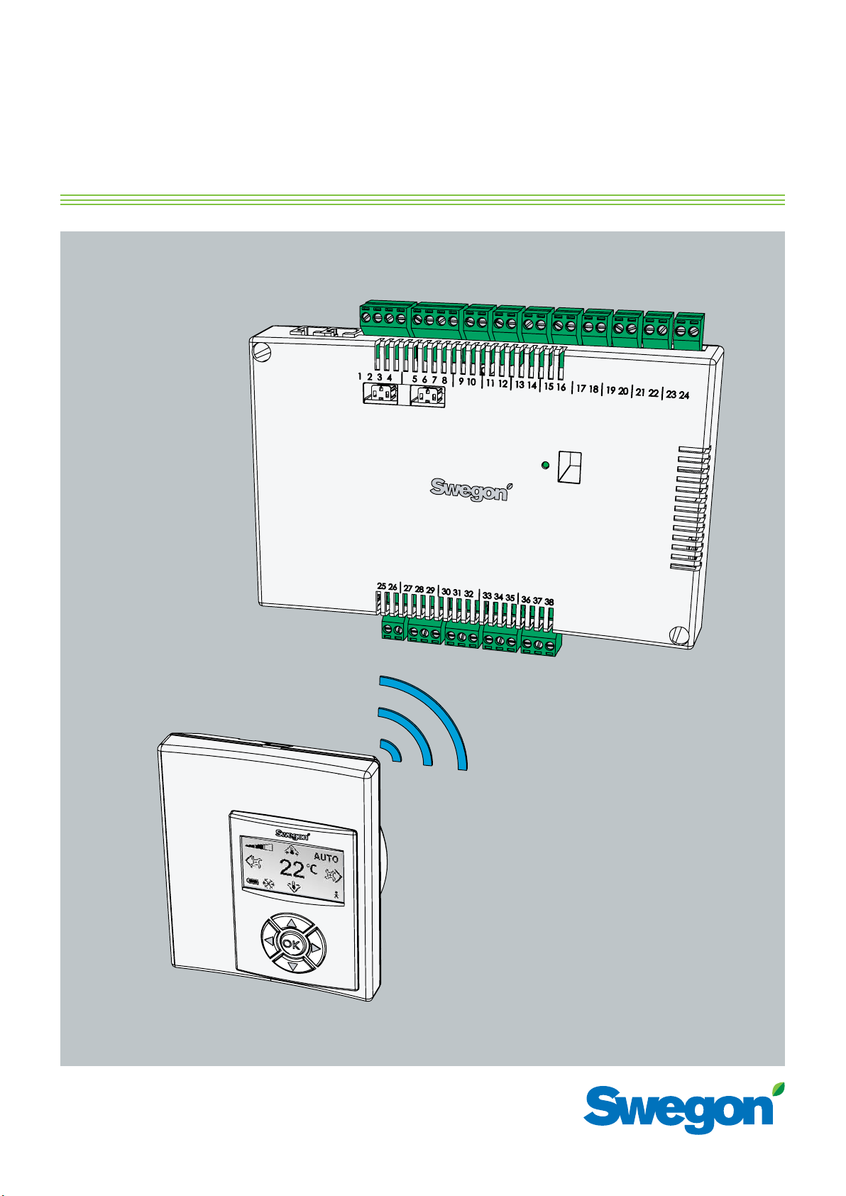
Controller and Room Unit (thermostat)
The main components in the CONDUCTOR W1/W3 control system are a
controller and a room unit (thermostat).
Controller
4
Technical Description
3
5
6
2
7
8
1
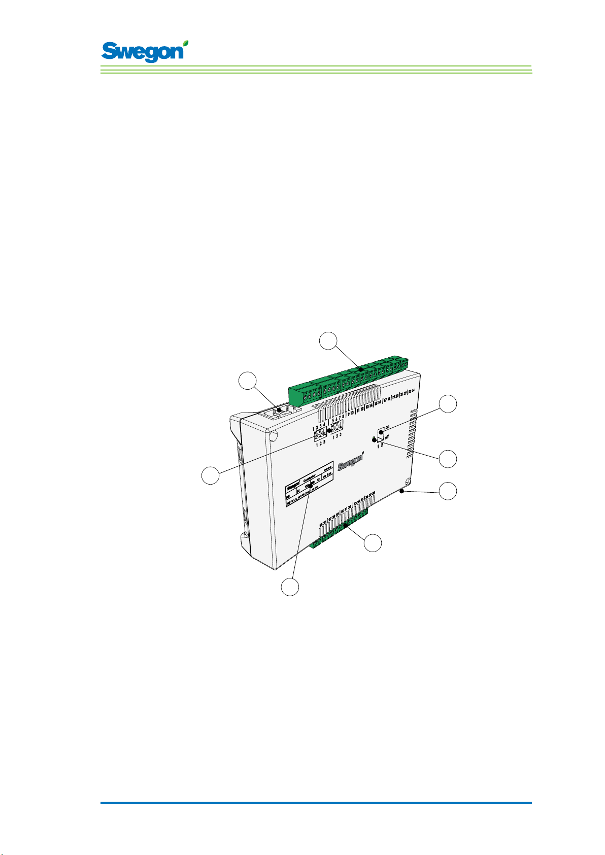
Figur 1. Overview of the Controller.
Pos 1. Product marking.
Pos 2. Termination resistance.
Pos 3. Modbus RTU units.
Pos 4. Inputs: Wiring terminals for the connection of sensors.
Pos 5. DIP switch for ModBUS RTU.
Pos 6. LED, indicates the status of the controller.
Pos 7. Input and output for signal to external relay.
Pos 8. Outputs: Wiring terminals for the connection of valve and damper actuators.
2 : 7
Technical Description
The controller is equipped with inputs for connection of a condensation
sensor, carbon dioxide sensor, window switch, presence detector and
outputs for the connection of actuators for valves and air dampers.
Up to twelve pairs of actuators (twelve for cooling + twelve for heating) can
be wired to each controller. Or you can connect up to four complete units
per controller for controlling both the airflow (supply air and central extract
air, 5 damper actuators) and cooling and heating (cooling and heating
circuit, valve actuators).
The controller provides proportional and integral (PI) control. Through
so-called PWM control (pulse width modulation), the I section senses both
the size and the duration of the control deviation and adjusts the actuator
opening time accordingly. It is possible to switch over from PWM control to
0-10 V control, if needed.
The user can easily configure the controller functions and parameters by
means of the room unit (thermostat).
The controller has a built-in communication port that enables connection to
an RS 485 network with ModBus RTU for supervising and override control
via a main control system.
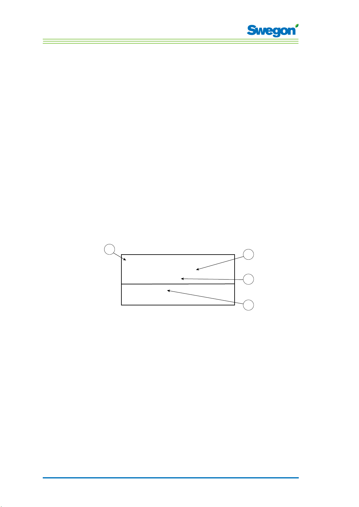
Product Identification Label
The product identification label affixed to the front of the controller,
indicates rated data, the controller ID-number, which you will need when
you install the CONDUCTOR.
1
2
Conductor RE W1
Modbus Adress 2
Artnr: 942334001
3
RF id: 00350
IIIIIIIIIIIIIIIIIIIIIIIIIIIIIII
4
Figur 2. Product identification label on the controller.
Pos 1. Name of the product.
Pos 2. ModBus RTU address.
Pos 3. Part number.
Pos 4. Controller ID number.
2 : 8
Room Unit
Technical Description
1
2
3
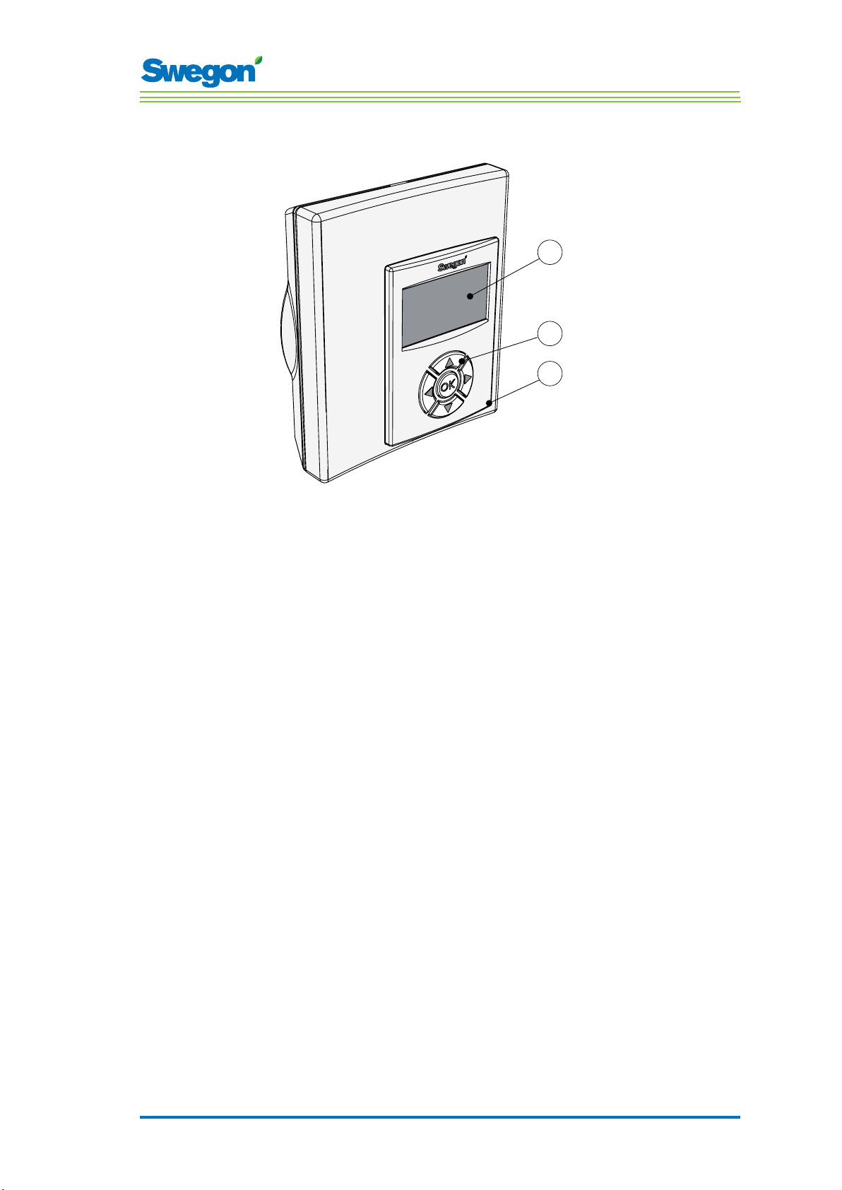
Figur 3. Overview of the room unit (thermostat).
Pos 1. Display
Pos 2. Keypad.
Pos 3. Temperature sensor.
The room unit is simple to use and has an easy-to-interpret design
that makes it user-friendly. The digital display shows the current preset
temperature and airflow settings.
The function of the room unit is to measure the temperature in the room,
communicate with the controller and to serve as a tool for adjusting the
climate in the room.
The internal communication between the controller and the room unit is
wireless, which makes it easier to find an appropriate spot in the room
where the room unit can be installed.
If requested, the room unit can be wire-connected with a RJ12 cable to the
controller.
2 : 9
Technical Description
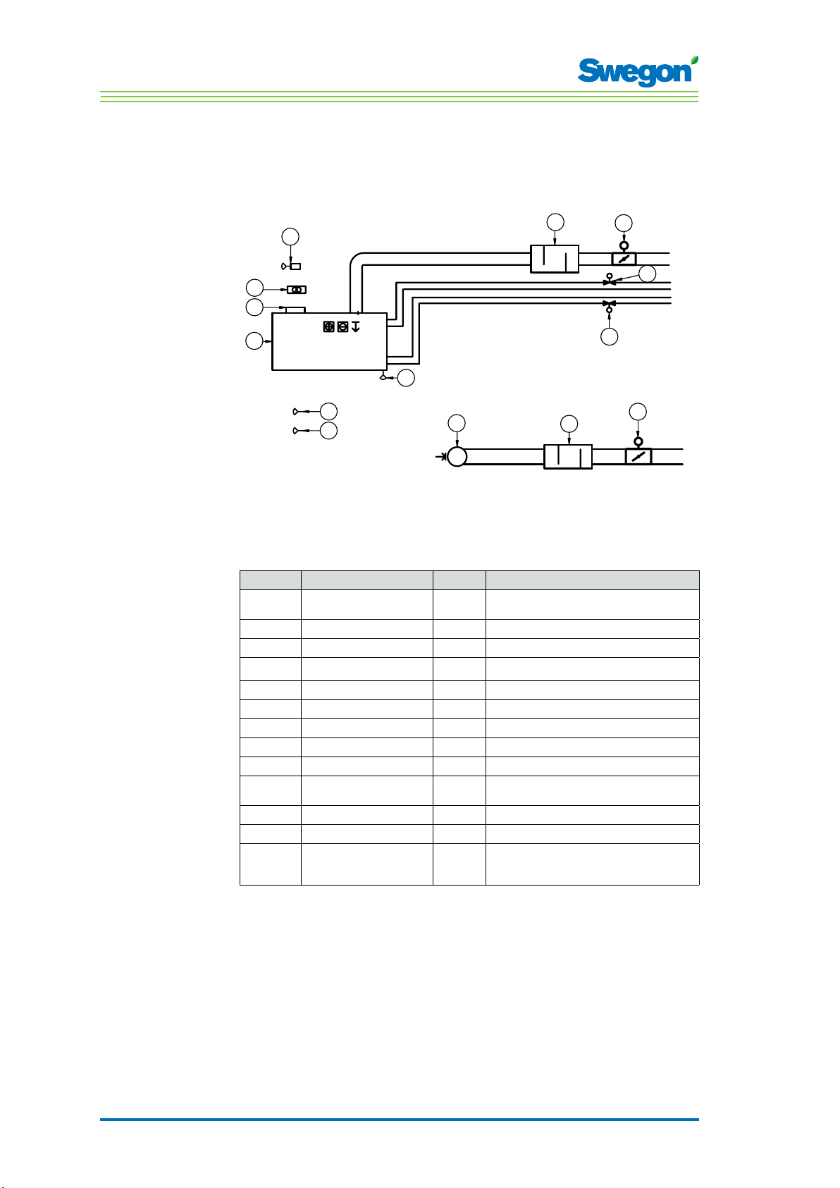
Installation Examples
The illustration below shows a typical arrangement of a complete
installation with the CONDUCTOR W1/W3 control system.
3
RU
GT
24V AC
4
RE
2
1
5
GX
GX
GX
7
6
12
Figur 4. Example of a CONDUCTOR W1/W3 installation.
Item Component Quantity Description
1.
2.
3.
4.
5.
6.
7.
8.
9.
10.
11.
12.
Accessories
PARASOL 1192-B-HF
CONDUCTOR RE W1/W3
CONDUCTOR RU
SYST TS-1
SYST CG
DETECT Occupancy 1 Presence detector
External
LUNA a AT-2
SYST VD 115-CLC
SYST CRTc 9-125-2 CM 24
CLA 125-500
Extract air register
SYST MS
Comfort module including cooling, heating and
1
ventilation
Controller
1
Room unit
1
Transformer
1
Condensation sensor
1
Window contact, not supplied by Swegon (W3)
1
Valve actuator
2
Control valve
2
Supply air damper 1 including motor (W3)
1
Extract air damper 1 including motor (W3)
Sound attenuator
1
Extract air register with given C-Factor
1
Assembly part for suspending the PARASOL
4
Not necessary if the product is mounted directly
against the ceiling.
11
10
9
8
10
11
2 : 10
Operating Mode
Applications
These instructions deal with two different applications: W1 and W3. W
indicates that both the applications are applicable to waterborne climate
systems.
A waterborne system provides the room with waterborne heating and
cooling. The air-based systems which can be controlled in the W3 by means
of connected damper actuators are only used to satisfy the demands on
air quality, while the temperature of the supply air and extract air is kept
constant.
Depending on the status of connected sensors, the controller adjusts the
outputs from any of several possible operating conditions. The various
operating conditions described here are based on occupancy in the room
and the status of the window switch and condensation sensor.
W1
Technical Description
W1 is a standard solution for offi ces, mainly designed for partitioned offi
ces, but which also can be used in large rooms, as with open-plan offi ces.
The application is suitable for so called CAV systems (Constant Air Volume),
which means that the airfl ow in the room is constant and that no damper
actuators are needed. Only two outputs are used, one for actuators that
control cooling and one for actuators that control heating. There is provision
for connecting a condensation sensor, a temperature sensor and an
presence detection sensor.
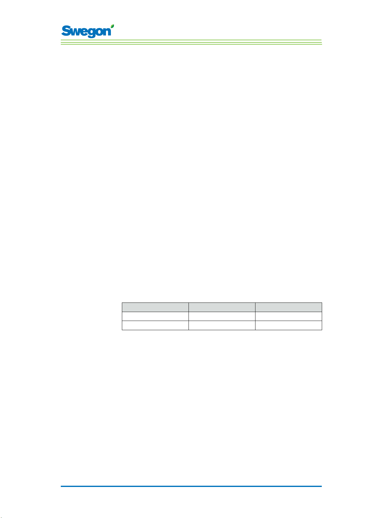
Table 1. Operating conditions for application W1
Condensation Cooling Heating
Yes Off Normal
No Normal Normal
2 : 11
Technical Description
W3
The W3-application can be used either for offi ces or for hotel rooms. It is
well-suited for systems with variable airfl ow (VAV) with both supply air and
extract air. Four outputs are used to control heating, cooling, supply and
extract air. The damper motors are adjusted depending on the generated
airfl ow and duct pressure in both the supply and extract air ducts.
Three inputs are used; for condensation sensors, window switches and
presence detectors. The principle is to use minimal, normal or high airfl ow,
depending on occupancy and sensor status.
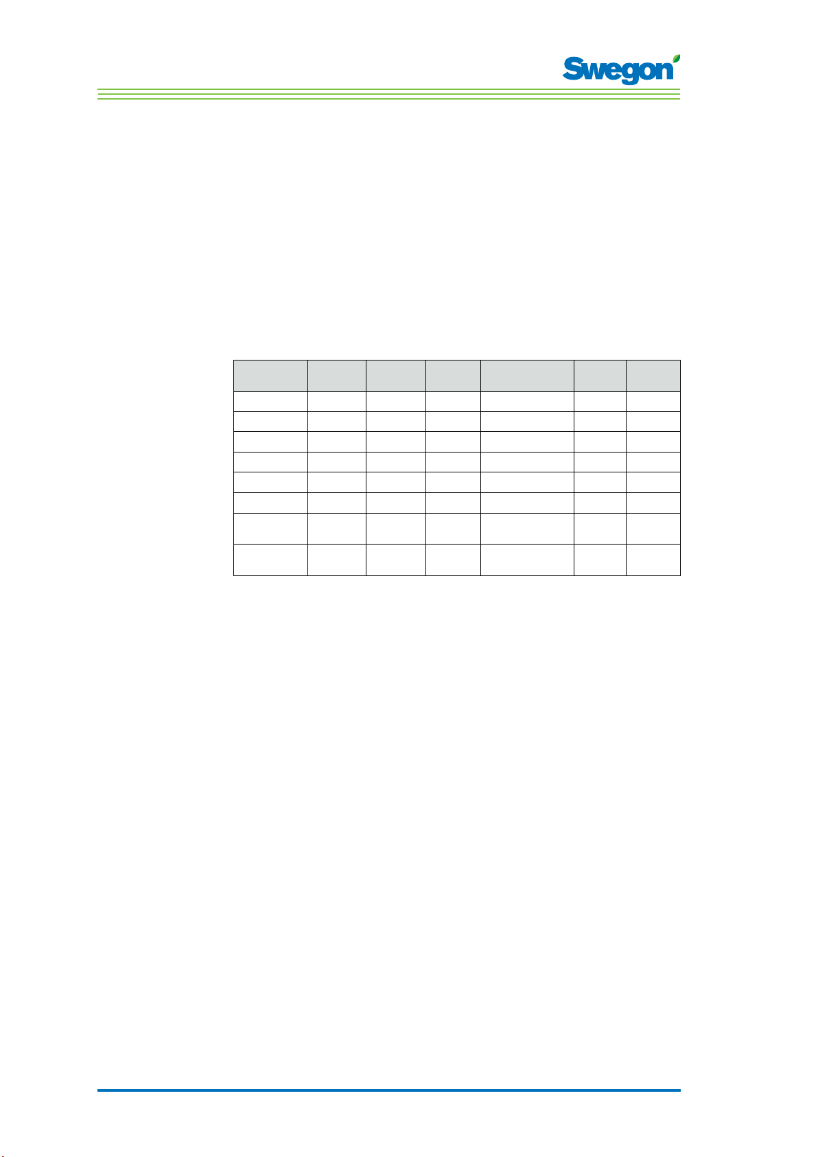
Table 3: Operating conditions for application W3
Occupancy Window Conden-
sation
Yes Yes Yes Off Frost protection Min. Min.
Yes Yes No Off Frost protection Min. Min.
Yes No Yes Off Normal Max. Max.
Yes No No Normal Normal Normal Normal
No Yes Yes Off Frost protection Min. Min.
No Yes No Off Frost protection Min. Min.
No No Yes Off
No No No Normal
Cooling Heating Supply
Normal/Energy
saving
Normal/Energy
saving
air
Min. Min.
Min. Min.
Extract
air
2 : 12

Operating Modes
There are a variety of functions built into the CONDUCTOR:
• MAN, manual mode.
• AUTO, automatic mode.
• ECON, energy-saving mode.
• Stand-by mode.
• EMERG, emergency mode.
MAN, Manual operating mode.
Whenever the CONDUCTOR registers occupancy in the room in response
to signals from a presence detector, the user can regulate the temperature
and airflow rate by entering settings in the room unit. When the user enters
a new desired setting, the controller switches over to the manual operating
mode (MAN).
AUTO, Automatic operating mode.
When the CONDUCTOR no longer registers occupancy in the room, the
controller automatically decreases the supply air flow to the low airflow
setting and the system automatically returns to the AUTO mode.
Technical Description
The controller also switches automatically to the AUTO mode after a
predefined number of minutes after the most recent change, manually
entered on the room unit.
When the controller is set to the automatic mode, the valve actuators for
chilled water and hot water respectively and the supply air damper and
extract air damper respectively are adjusted in response to occupancy in the
room and the level of carbon dioxide as well as the status of the window
contact and the condensation sensor.
The automatic control system controls the airflow, cooling and heating until
the user manually enters a new airflow or temperature setting.
ECON, energy-saving mode.
When the energy-saving function is enabled, the system switches
automatically to the ECON energy-saving mode, when no occupancy has
been registered for a predefined number of minutes. The system returns to
the AUTO mode when occupancy is registered again.
In the energy-save mode, the valve actuator is controlled for chilled water
and hot water respectively according to the status on other sensors in the
room, but with a greater permissible difference between actual value and
setpoint than in the AUTO mode.
2 : 13

Technical Description
Stand-by mode.
When the control system registers a signal indicating that a window is open,
the controller switches over to the standby mode. When the window is
closed, the controller switches to the AUTO operating mode.
While the controller is in the Stand-by mode, the room temperature is
maintained above the predefined level for the Frost protection function.
EMERG, emergency mode.
In the event of a fire alarm, the air damper in the extract air duct is opened
or closed, depending on the setting entered in the control system. The
cooling and heating functions are shut off while the system is in the EMERG
mode. The supply air is normally shut off.
The EMERG mode can only be managed in control systems that are
connected to a main control system via ModBus RTU.
Functions
There are a variety of functions built into the CONDUCTOR W1/W3:
• Exercising of valves
• First open
• Frost protection
• Change over
• Night cool
• Time-set setpoint restoration
Exercising of valves
The function involves regularly exercising the water valves by utilising
automated functions in order to prevent them from becoming sluggish or
jamming. During the exercising period, all the valves that are wired to the
controller are opened for a maximum of 6 minutes and are then closed.
The valves for the cooling system are exercised first. Then the valves for the
heating system are exercised.
First open
The function means that the water valves are open when the system is
installed, which makes it easier to fill, pressure test and vent the water
system.
The function will be automatically disabled after the actuator has been
energized for approx. 6 minutes. A clicking noise will be heard when the
valves and the dampers change over to the NC mode (=normally closed)
and the normal control function is enabled.
2 : 14

Technical Description
Frost protection
The function involves the following: Heating operation is started at a
predefined room temperature in order to counteract the risk of damage that
otherwise can arise due to freezing.
Change over
The function involves the use of only one valve actuator which should be
wired to the cooling output terminal. This actuator then controls both the
heating water and the cooling water, which are transported in the same
pipe.
In winter, when heating is required, the valve opens if the water in the pipe
is warmer than the temperature setpoint. If the water is colder, the valve
does not open.
In summer, when cooling is required, the valve opens if the water in the pipe
is colder than the temperature setpoint.
In order to be able to use this function, you are required to mount an
external temperature sensor onto the water pipe through which supply
water circulates continuously. Wire the sensor according to the general
wiring diagram shown in the section entitled: Installation
Night cool
The function involves using cold air from outdoors for cooling the room at
night to the predefined level.
The function can only be managed in control systems that are connected to
a main control system via ModBus RTU.
Time-set setpoint restoration
The function involves adjusting the room temperature to the predefined
level when the controller switches to the AUTO operating mode.
The controller also switches automatically to the AUTO mode after a
predefined number of minutes after the most recent change, manually
entered on the room unit.
2 : 15
Technical Description
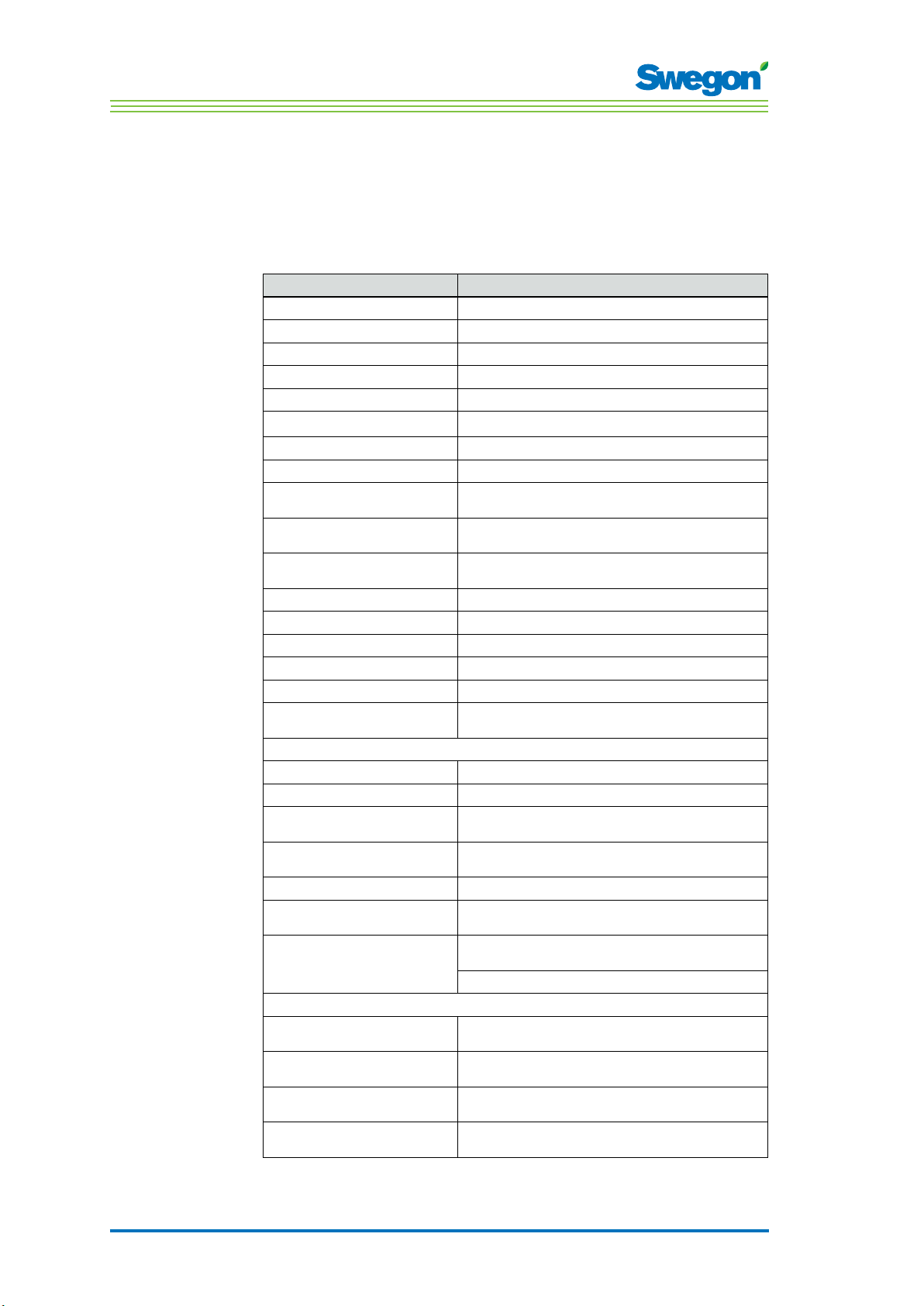
Technical Data
CONDUCTOR RE Controller
Technical data applicable to the CONDUCTOR RE controller (W1/W3) is
specified below.
Item Data
Designation CONDUCTOR RE (W1/W3)
Storage temperature -40 °C to +80 °C
Operating temperature -20 °C to +50 °C
Degree of protection IP 32
Dimensions 121 x 193 x 44 mm
Supply voltage 24V AC ± 10%
Power consumption 1 VA
Control function PI
P-band, cooling/heating
increments
Dead band, occupancy in
room
Dead band, no occupancy Depends on switching in cooling and switching in
Frost protection 10 °C
Valve installation 1 time/48h period (fully open for 3 minutes)
Installation Mounting holes in enclosure or onto DIN rail
Connections Wiring terminal for 2.5 mm² multicore cable
Data communication ModBus RTU
Wireless communication 433 MHz band radio modem with room unit
Inputs
Condensation sensor Resistance
Temperature sensor Resistance
Presence detector No occupancy/NO/NC (optional), default = NC for
Window contact
Carbon dioxide sensor 2 - 10 V, or 24 V
Pressure sensor / ModBus RTU
sensor
Modular contact RJ12 6-pole for connecting up to the room unit
Outputs
Actuator, heating 24 V AC, PWM (on/off or 0 - 10 V) max load: 72
Actuator, cooling 24 V AC, PWM (on/off or 0 - 10 V) max load: 72
Supply air damper
Extract air damper
(W3) No occupancy/NO/NC (optional), default = NC for
(W3) 0 - 10 V DC (low/normal/high) max load 25 VA =
(W3) 0 - 10 V DC (low/normal/high) max load 25 VA =
1 K
Depends on switching in cooling and switching in
heating
heating
(thermostat)
occupancy
closed window
2 - 10 V / RJ12 cable
(thermostat)
RJ12 6-pole for connecting up to ModBus RTU
VA = 12 actuators
VA = 12 actuators
5 actuators.
5 actuators.
2 : 16
Technical Description
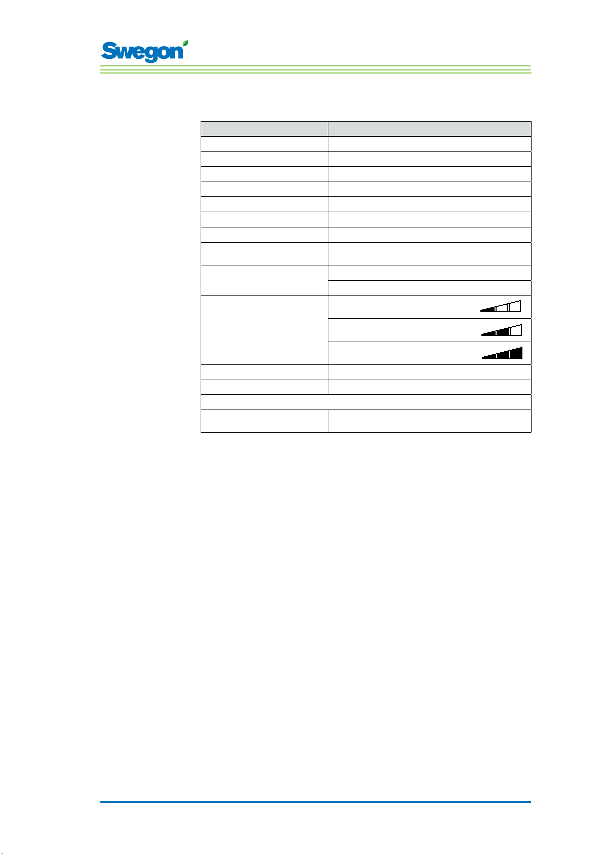
CONDUCTOR RU room unit (thermostat)
Item Data
Designation: CONDUCTOR RU
Storage temperature -40 °C to +80 °C (*)
Operating temperature 0 °C to +50°C
Degree of protection IP 20
Dimensions 86 x 100 x 32 mm
Supply voltage 12 V, 4 size AAA batteries
Actual value, range +10 °C to +32°C
Installation Against a wall or in a 70 mm standard junction
In-operation LED, temperature Cooling load
In-operation LED, air Low airflow:
In-operation LED, enabled Lit LED, AUTO
In-operation LED, disabled Dimmed display, AUTO
Input
Modular contact RJ12 6-pole for connecting up to the controller
(*) = Specified storage temperature appies to a room unit WITHOUT batteries.
(**) = Used only if wireless communication is not desired.
box. Must not be exposed to direct sunlight
Heating load
One LED lit
Normal airflow:
Two LEDs lit
High airflow:
Three LEDs lit
(**)
2 : 17

Technical Description
2 : 18
Installation
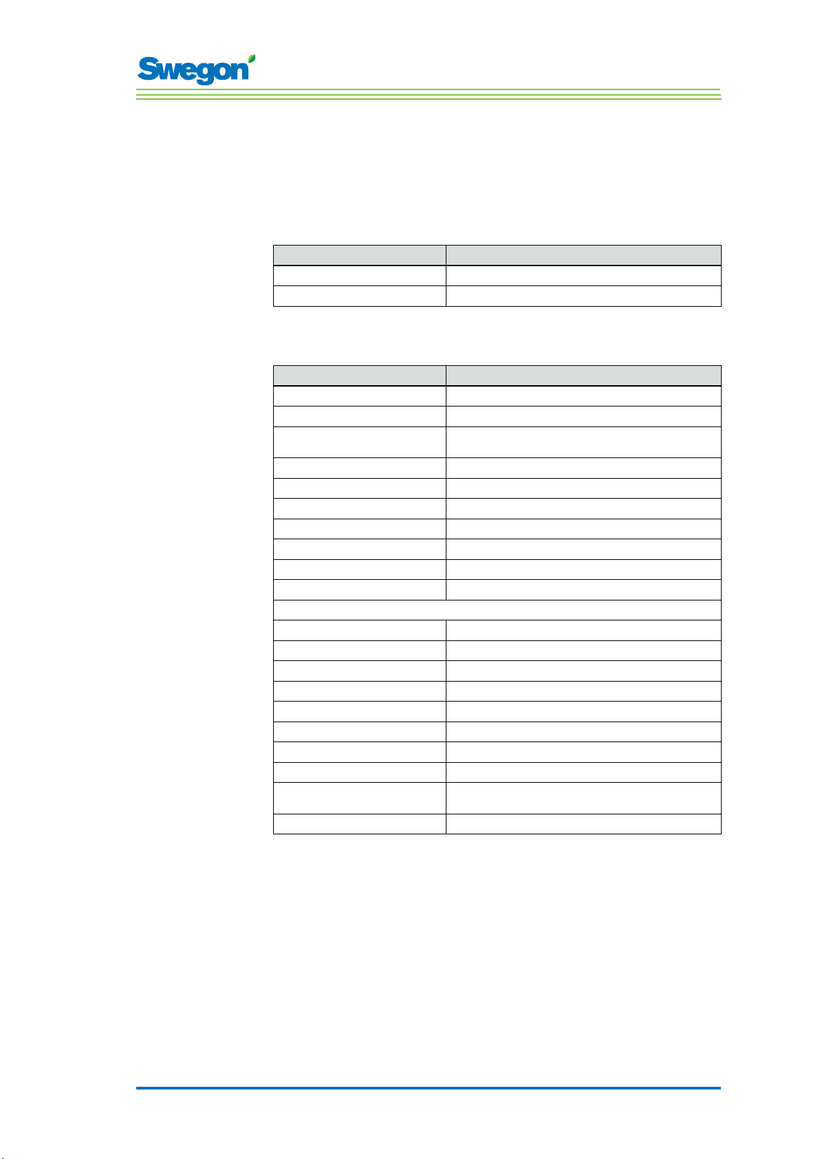
Ordering, delivery and electrical installation
Ordering key, Control equipment
Item Data
Controller W1/W3 CONDUCTOR RE (aa)
Room unit (Thermostat) CONDUCTOR RU
Ordering Key, Accessories
Item Data
Valve SYST VD 115-CLC
Valve actuator LUNA a AT-2
Ventilation damper incl.
damper actuator
Adapter, actuator/valve LUNA a T-VA-(aa)
Condensation sensor SYST CG
Carbon dioxide sensor DETECT Quality
Presence detector DETECT Occupancy
Modular cable RJ12 6/6, 5 metres long
Transformer SYST TS-1
External temperature sensor CONDUCTOR T-TG
SYST CRTc 9 (aaa)-2-CM-24
Installation
(aa) = Fitted to valve type:
32 Tour & Andersson
39 Oventrop
50 Honeywell, Reich, MNG, Böhnisch (H), Cazzaniga
54 Certain MMA-valves
59 Danfoss RAV/L
72 Danfoss RAV
78 Danfoss RA
80 Siemens and more (always included in the LUNA a
(aaa) = 125 or 160
AT-2 actuator)
3 : 19
 Loading...