

Page 1
CONDUCTORTM W1/W3
Technical Manual
Updated : 2012-11-16
SW version 0.76
Page 2

Page 3

Contents
Contents
Introduction and Safety .....................................5
About this Manual .................................................. 5
Product Design Changes ......................................... 5
Safety Precautions .................................................. 5
Technical Description ......................................... 7
About Conductor W1/W3 ...................................... 7
Controller and Room Unit (thermostat) ................... 7
Installation Examples .............................................10
Operating Mode .................................................... 11
Operating Modes ..................................................13
Functions ...............................................................14
Technical Data RE Controller ..................................16
Technical Data RU room unit..................................17
Installation ....................................................... 19
Ordering, Delivery and Electrical Installation ...........19
Preparations ..........................................................20
Step 1, To Mount the Controller. ............................21
Step 2, To Connect the Units .................................23
Step 3, Commissioning ..........................................24
Step 4, To Install the Room Unit (thermostat) .........26
The Menus of the Room Unit RU (thermostat) ... 27
The Main Image and the Key Pad of the RU ...........27
Overview of the Menu System of the RU ...............29
Navigating in the Menus of the Room Unit ........... 30
Changes in the Main Image ...................................31
Changes and Settings in the Service Menu ............32
Service ............................................................. 41
Parameters ............................................................41
System Parameters.................................................41
Application Parameters
W1 ........................................................................43
W3 ........................................................................45
Indications on the Controller ..................................49
Troubleshooting ................................................... 50
ModBus Register W1 .............................................52
ModBus Register W3 ........................................... 58
3
Page 4

Contents
4
Page 5

Introduction and safety
About this manual
This manual is intended for use by the members of the staff who are
responsible for maintenance of the climate system and it contains the
following information:
• Technical description of the CONDUCTOR W1/W3 controller.
• Installing and commissioning the CONDUCTOR W1/W3 controller .
• Instructions on how the various settings should be entered in the room
unit (thermostat).
The Service section is intended for personnel who are specially trained by
Swegon.
Product design changes
Swegon reserves the right to change the specifications in the manual and
change the design of the product without notice.
Safety precautions
Introduction and Safety
Responsibility
It is the responsibility of the user to do the following:
• Assess all the risks involved in the activities which are related to this
manual.
• Make sure that all necessary safety precautions are made before
starting the activities which are related to this manual.
Safety levels
The following levels of safety warnings are used in this manual:
WARNING:
Used when there is risk of damage to persons or
equipment.
N.B.!
Used to point out important information.
1 : 5
Page 6

Introduction and Safety
1 : 6
Page 7
Technical Description
About Conductor W1/W3
CONDUCTOR W1/W3 is a controller application in the CONDUCTOR series.
The W designation indicates that the application is applicable to waterborne climate systems.
CONDUCTOR is a control system for the individual control of room
temperature and airflow (W3)., especially adapted for partitioned offices
and hotel rooms. It can operate independently or in combination with a
central system.
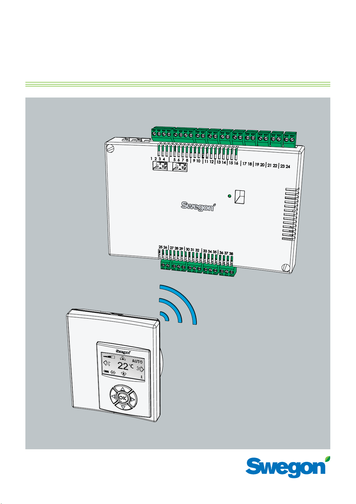
Controller and Room Unit (thermostat)
The main components in the CONDUCTOR W1/W3 control system are a
controller and a room unit (thermostat).
Controller
4
Technical Description
3
5
6
2
7
8
1
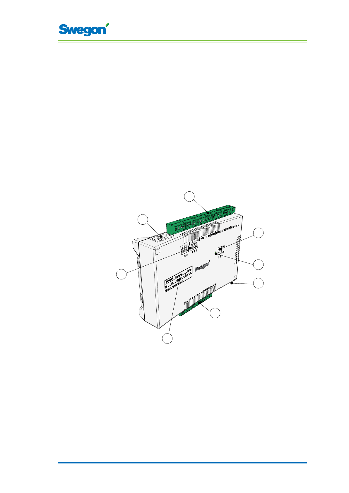
Figur 1. Overview of the Controller.
Pos 1. Product marking.
Pos 2. Termination resistance.
Pos 3. Modbus RTU units.
Pos 4. Inputs: Wiring terminals for the connection of sensors.
Pos 5. DIP switch for ModBUS RTU.
Pos 6. LED, indicates the status of the controller.
Pos 7. Input and output for signal to external relay.
Pos 8. Outputs: Wiring terminals for the connection of valve and damper actuators.
2 : 7
Page 8
Technical Description
The controller is equipped with inputs for connection of a condensation
sensor, carbon dioxide sensor, window switch, presence detector and
outputs for the connection of actuators for valves and air dampers.
Up to twelve pairs of actuators (twelve for cooling + twelve for heating) can
be wired to each controller. Or you can connect up to four complete units
per controller for controlling both the airflow (supply air and central extract
air, 5 damper actuators) and cooling and heating (cooling and heating
circuit, valve actuators).
The controller provides proportional and integral (PI) control. Through
so-called PWM control (pulse width modulation), the I section senses both
the size and the duration of the control deviation and adjusts the actuator
opening time accordingly. It is possible to switch over from PWM control to
0-10 V control, if needed.
The user can easily configure the controller functions and parameters by
means of the room unit (thermostat).
The controller has a built-in communication port that enables connection to
an RS 485 network with ModBus RTU for supervising and override control
via a main control system.
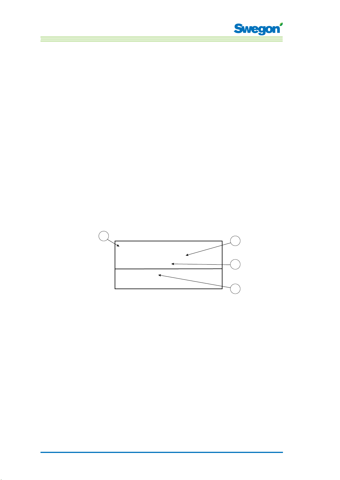
Product Identification Label
The product identification label affixed to the front of the controller,
indicates rated data, the controller ID-number, which you will need when
you install the CONDUCTOR.
1
2
Conductor RE W1
Modbus Adress 2
Artnr: 942334001
3
RF id: 00350
IIIIIIIIIIIIIIIIIIIIIIIIIIIIIII
4
Figur 2. Product identification label on the controller.
Pos 1. Name of the product.
Pos 2. ModBus RTU address.
Pos 3. Part number.
Pos 4. Controller ID number.
2 : 8
Page 9
Room Unit
Technical Description
1
2
3
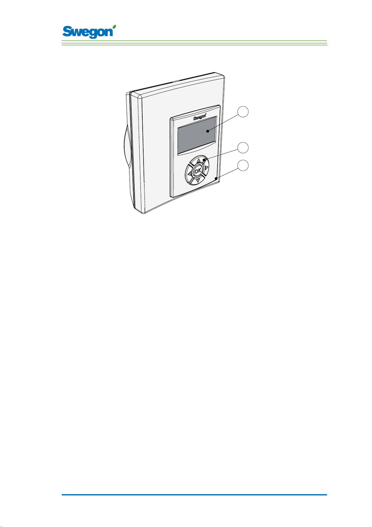
Figur 3. Overview of the room unit (thermostat).
Pos 1. Display
Pos 2. Keypad.
Pos 3. Temperature sensor.
The room unit is simple to use and has an easy-to-interpret design
that makes it user-friendly. The digital display shows the current preset
temperature and airflow settings.
The function of the room unit is to measure the temperature in the room,
communicate with the controller and to serve as a tool for adjusting the
climate in the room.
The internal communication between the controller and the room unit is
wireless, which makes it easier to find an appropriate spot in the room
where the room unit can be installed.
If requested, the room unit can be wire-connected with a RJ12 cable to the
controller.
2 : 9
Page 10
Technical Description
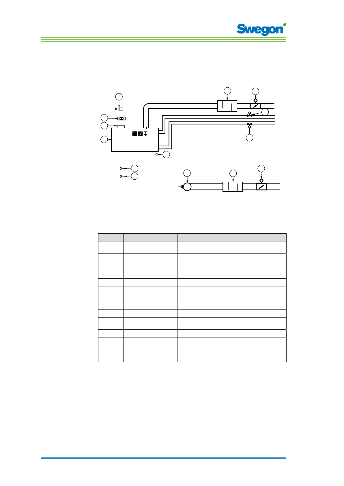
Installation Examples
The illustration below shows a typical arrangement of a complete
installation with the CONDUCTOR W1/W3 control system.
3
RU
GT
24V AC
4
RE
2
1
5
GX
GX
GX
7
6
12
Figur 4. Example of a CONDUCTOR W1/W3 installation.
Item Component Quantity Description
1.
2.
3.
4.
5.
6.
7.
8.
9.
10.
11.
12.
Accessories
PARASOL 1192-B-HF
CONDUCTOR RE W1/W3
CONDUCTOR RU
SYST TS-1
SYST CG
DETECT Occupancy 1 Presence detector
External
LUNA a AT-2
SYST VD 115-CLC
SYST CRTc 9-125-2 CM 24
CLA 125-500
Extract air register
SYST MS
Comfort module including cooling, heating and
1
ventilation
Controller
1
Room unit
1
Transformer
1
Condensation sensor
1
Window contact, not supplied by Swegon (W3)
1
Valve actuator
2
Control valve
2
Supply air damper 1 including motor (W3)
1
Extract air damper 1 including motor (W3)
Sound attenuator
1
Extract air register with given C-Factor
1
Assembly part for suspending the PARASOL
4
Not necessary if the product is mounted directly
against the ceiling.
11
10
9
8
10
11
2 : 10
Page 11

Operating Mode
Applications
These instructions deal with two different applications: W1 and W3. W
indicates that both the applications are applicable to waterborne climate
systems.
A waterborne system provides the room with waterborne heating and
cooling. The air-based systems which can be controlled in the W3 by means
of connected damper actuators are only used to satisfy the demands on
air quality, while the temperature of the supply air and extract air is kept
constant.
Depending on the status of connected sensors, the controller adjusts the
outputs from any of several possible operating conditions. The various
operating conditions described here are based on occupancy in the room
and the status of the window switch and condensation sensor.
W1
Technical Description
W1 is a standard solution for offi ces, mainly designed for partitioned offi
ces, but which also can be used in large rooms, as with open-plan offi ces.
The application is suitable for so called CAV systems (Constant Air Volume),
which means that the airfl ow in the room is constant and that no damper
actuators are needed. Only two outputs are used, one for actuators that
control cooling and one for actuators that control heating. There is provision
for connecting a condensation sensor, a temperature sensor and an
presence detection sensor.
Table 1. Operating conditions for application W1
Condensation Cooling Heating
Yes Off Normal
No Normal Normal
2 : 11
Page 12

Technical Description
W3
The W3-application can be used either for offi ces or for hotel rooms. It is
well-suited for systems with variable airfl ow (VAV) with both supply air and
extract air. Four outputs are used to control heating, cooling, supply and
extract air. The damper motors are adjusted depending on the generated
airfl ow and duct pressure in both the supply and extract air ducts.
Three inputs are used; for condensation sensors, window switches and
presence detectors. The principle is to use minimal, normal or high airfl ow,
depending on occupancy and sensor status.
Table 3: Operating conditions for application W3
Occupancy Window Conden-
sation
Yes Yes Yes Off Frost protection Min. Min.
Yes Yes No Off Frost protection Min. Min.
Yes No Yes Off Normal Max. Max.
Yes No No Normal Normal Normal Normal
No Yes Yes Off Frost protection Min. Min.
No Yes No Off Frost protection Min. Min.
No No Yes Off
No No No Normal
Cooling Heating Supply
Normal/Energy
saving
Normal/Energy
saving
air
Min. Min.
Min. Min.
Extract
air
2 : 12
Page 13

Operating Modes
There are a variety of functions built into the CONDUCTOR:
• MAN, manual mode.
• AUTO, automatic mode.
• ECON, energy-saving mode.
• Stand-by mode.
• EMERG, emergency mode.
MAN, Manual operating mode.
Whenever the CONDUCTOR registers occupancy in the room in response
to signals from a presence detector, the user can regulate the temperature
and airflow rate by entering settings in the room unit. When the user enters
a new desired setting, the controller switches over to the manual operating
mode (MAN).
AUTO, Automatic operating mode.
When the CONDUCTOR no longer registers occupancy in the room, the
controller automatically decreases the supply air flow to the low airflow
setting and the system automatically returns to the AUTO mode.
Technical Description
The controller also switches automatically to the AUTO mode after a
predefined number of minutes after the most recent change, manually
entered on the room unit.
When the controller is set to the automatic mode, the valve actuators for
chilled water and hot water respectively and the supply air damper and
extract air damper respectively are adjusted in response to occupancy in the
room and the level of carbon dioxide as well as the status of the window
contact and the condensation sensor.
The automatic control system controls the airflow, cooling and heating until
the user manually enters a new airflow or temperature setting.
ECON, energy-saving mode.
When the energy-saving function is enabled, the system switches
automatically to the ECON energy-saving mode, when no occupancy has
been registered for a predefined number of minutes. The system returns to
the AUTO mode when occupancy is registered again.
In the energy-save mode, the valve actuator is controlled for chilled water
and hot water respectively according to the status on other sensors in the
room, but with a greater permissible difference between actual value and
setpoint than in the AUTO mode.
2 : 13
Page 14

Technical Description
Stand-by mode.
When the control system registers a signal indicating that a window is open,
the controller switches over to the standby mode. When the window is
closed, the controller switches to the AUTO operating mode.
While the controller is in the Stand-by mode, the room temperature is
maintained above the predefined level for the Frost protection function.
EMERG, emergency mode.
In the event of a fire alarm, the air damper in the extract air duct is opened
or closed, depending on the setting entered in the control system. The
cooling and heating functions are shut off while the system is in the EMERG
mode. The supply air is normally shut off.
The EMERG mode can only be managed in control systems that are
connected to a main control system via ModBus RTU.
Functions
There are a variety of functions built into the CONDUCTOR W1/W3:
• Exercising of valves
• First open
• Frost protection
• Change over
• Night cool
• Time-set setpoint restoration
Exercising of valves
The function involves regularly exercising the water valves by utilising
automated functions in order to prevent them from becoming sluggish or
jamming. During the exercising period, all the valves that are wired to the
controller are opened for a maximum of 6 minutes and are then closed.
The valves for the cooling system are exercised first. Then the valves for the
heating system are exercised.
First open
The function means that the water valves are open when the system is
installed, which makes it easier to fill, pressure test and vent the water
system.
The function will be automatically disabled after the actuator has been
energized for approx. 6 minutes. A clicking noise will be heard when the
valves and the dampers change over to the NC mode (=normally closed)
and the normal control function is enabled.
2 : 14
Page 15

Technical Description
Frost protection
The function involves the following: Heating operation is started at a
predefined room temperature in order to counteract the risk of damage that
otherwise can arise due to freezing.
Change over
The function involves the use of only one valve actuator which should be
wired to the cooling output terminal. This actuator then controls both the
heating water and the cooling water, which are transported in the same
pipe.
In winter, when heating is required, the valve opens if the water in the pipe
is warmer than the temperature setpoint. If the water is colder, the valve
does not open.
In summer, when cooling is required, the valve opens if the water in the pipe
is colder than the temperature setpoint.
In order to be able to use this function, you are required to mount an
external temperature sensor onto the water pipe through which supply
water circulates continuously. Wire the sensor according to the general
wiring diagram shown in the section entitled: Installation
Night cool
The function involves using cold air from outdoors for cooling the room at
night to the predefined level.
The function can only be managed in control systems that are connected to
a main control system via ModBus RTU.
Time-set setpoint restoration
The function involves adjusting the room temperature to the predefined
level when the controller switches to the AUTO operating mode.
The controller also switches automatically to the AUTO mode after a
predefined number of minutes after the most recent change, manually
entered on the room unit.
2 : 15
Page 16

Technical Description
Technical Data
CONDUCTOR RE Controller
Technical data applicable to the CONDUCTOR RE controller (W1/W3) is
specified below.
Item Data
Designation CONDUCTOR RE (W1/W3)
Storage temperature -40 °C to +80 °C
Operating temperature -20 °C to +50 °C
Degree of protection IP 32
Dimensions 121 x 193 x 44 mm
Supply voltage 24V AC ± 10%
Power consumption 1 VA
Control function PI
P-band, cooling/heating
increments
Dead band, occupancy in
room
Dead band, no occupancy Depends on switching in cooling and switching in
Frost protection 10 °C
Valve installation 1 time/48h period (fully open for 3 minutes)
Installation Mounting holes in enclosure or onto DIN rail
Connections Wiring terminal for 2.5 mm² multicore cable
Data communication ModBus RTU
Wireless communication 433 MHz band radio modem with room unit
Inputs
Condensation sensor Resistance
Temperature sensor Resistance
Presence detector No occupancy/NO/NC (optional), default = NC for
Window contact
Carbon dioxide sensor 2 - 10 V, or 24 V
Pressure sensor / ModBus RTU
sensor
Modular contact RJ12 6-pole for connecting up to the room unit
Outputs
Actuator, heating 24 V AC, PWM (on/off or 0 - 10 V) max load: 72
Actuator, cooling 24 V AC, PWM (on/off or 0 - 10 V) max load: 72
Supply air damper
Extract air damper
(W3) No occupancy/NO/NC (optional), default = NC for
(W3) 0 - 10 V DC (low/normal/high) max load 25 VA =
(W3) 0 - 10 V DC (low/normal/high) max load 25 VA =
1 K
Depends on switching in cooling and switching in
heating
heating
(thermostat)
occupancy
closed window
2 - 10 V / RJ12 cable
(thermostat)
RJ12 6-pole for connecting up to ModBus RTU
VA = 12 actuators
VA = 12 actuators
5 actuators.
5 actuators.
2 : 16
Page 17
Technical Description
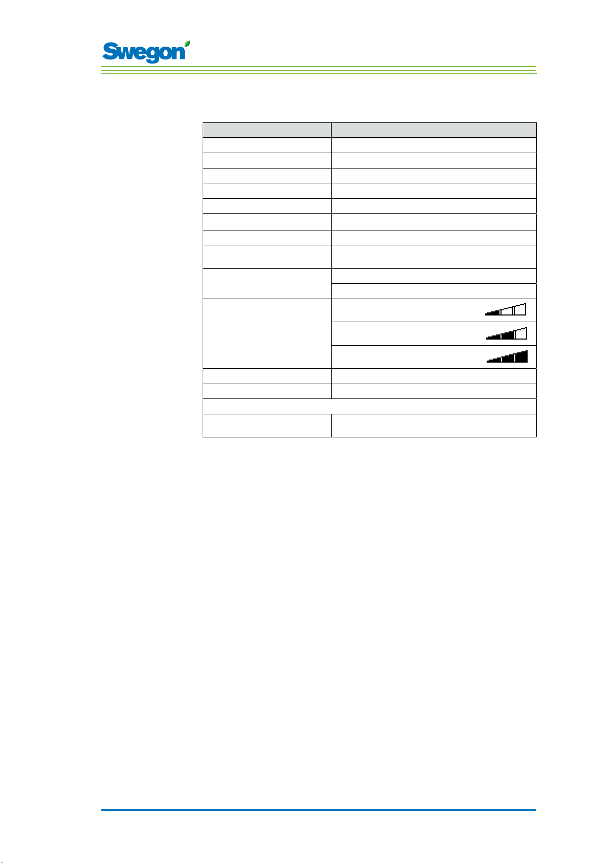
CONDUCTOR RU room unit (thermostat)
Item Data
Designation: CONDUCTOR RU
Storage temperature -40 °C to +80 °C (*)
Operating temperature 0 °C to +50°C
Degree of protection IP 20
Dimensions 86 x 100 x 32 mm
Supply voltage 12 V, 4 size AAA batteries
Actual value, range +10 °C to +32°C
Installation Against a wall or in a 70 mm standard junction
In-operation LED, temperature Cooling load
In-operation LED, air Low airflow:
In-operation LED, enabled Lit LED, AUTO
In-operation LED, disabled Dimmed display, AUTO
Input
Modular contact RJ12 6-pole for connecting up to the controller
(*) = Specified storage temperature appies to a room unit WITHOUT batteries.
(**) = Used only if wireless communication is not desired.
box. Must not be exposed to direct sunlight
Heating load
One LED lit
Normal airflow:
Two LEDs lit
High airflow:
Three LEDs lit
(**)
2 : 17
Page 18

Technical Description
2 : 18
Page 19

Installation
Ordering, delivery and electrical installation
Ordering key, Control equipment
Item Data
Controller W1/W3 CONDUCTOR RE (aa)
Room unit (Thermostat) CONDUCTOR RU
Ordering Key, Accessories
Item Data
Valve SYST VD 115-CLC
Valve actuator LUNA a AT-2
Ventilation damper incl.
damper actuator
Adapter, actuator/valve LUNA a T-VA-(aa)
Condensation sensor SYST CG
Carbon dioxide sensor DETECT Quality
Presence detector DETECT Occupancy
Modular cable RJ12 6/6, 5 metres long
Transformer SYST TS-1
External temperature sensor CONDUCTOR T-TG
SYST CRTc 9 (aaa)-2-CM-24
Installation
(aa) = Fitted to valve type:
32 Tour & Andersson
39 Oventrop
50 Honeywell, Reich, MNG, Böhnisch (H), Cazzaniga
54 Certain MMA-valves
59 Danfoss RAV/L
72 Danfoss RAV
78 Danfoss RA
80 Siemens and more (always included in the LUNA a
(aaa) = 125 or 160
AT-2 actuator)
3 : 19
Page 20

Installation
Ordering
Specify the desired number of ordered components or refer to drawing.
Delivery
• The valves are delivered to the plumbing contractor for installation in
the system.
• The room controller is delivered to the electrical contractor, systems
contractor or other contractor for installation onto the junction box.
• Controller is normally delivered factory fitted on the comfort module
or climate beam. The controller is delivered to electrical contractor,
systems contractor or other contractor for installation by means of
screws at some other suitable place, if separate components are
supplied.
WARNING:
All electrical installation, including wiring the actuators,
valve actuators and various sensors is to be carried out by
the electrical contractor or the systems contractor.
The electrical contractor or the systems contractor provides a 230 V earthed
outlet for transformer, a fitted junction box for the room unit (thermostat)
and possible external cables.
Preparations
The CONDUCTOR W1/W3 should be installed in steps as follows:
1. To mount the controller.
2. To connect units.
3. Commissioning.
4. To mount the room unit (thermostat).
Check the following before installing the CONDUCTOR W1/W3:
• The comfort module, with pre-fitted valve actuators for chilled and hot
water, are mounted in the ceiling.
• The required sensors (e.g. presence detector, window contact and
condensation sensor) are installed in the room.
• Required actuators are installed.
• Cables from all the units are marked and run up to the comfort
module, or alternative location for the controller.
The following are required for installation:
• ordinary screwdriver or electric screwdriver
• Electric drill.
3 : 20
Page 21

Step 1, To mount the controller.
Mounting on a DIN rail
If a DIN rail is mounted on the comfort module or at another suitable
location, the controller should be fastened to this rail.
Installation
1
2
3
4
Figur 1. To mount the controller.
Pos 1. Plastic hooks
Pos 2. Supporting surface, for example a comfort module or climate beam.
Pos 3. DIN rail
Pos 4. Snap-on fastener.
1. Fasten the two plastic hooks on the backside of the controller on the
upper control edge on the DIN rail.
2. Press to fasten the snap-on fasteners on the backside of the controller
against the lower control edge on the DIN rail.
3 : 21
Page 22

Installation
To be installed above a false ceiling
If a DIN rail is NOT available pre-mounted or is not available, the controller
can be appropriately mounted above the false ceiling (not on the module).
1
2
Figur 2. To mount the controller.
Pos 1. Supporting surface, NOT for the comfort module or climate beam.
Pos 2. Screws.
1. Secure the controller by means of screws in the upper left-hand and
the lower right-hand corners. Use screws suitable for the supporting
surface.
3 : 22
Page 23

Step 2, Installation of units
The following units should be connected to the detachable wiring terminals
of the controller:
Installation
5
4
3
1
Figur 3. Overview of the units.
Pos 1. Valve actuator for cooling water.
Pos 2. Valve actuator for heating water
Pos 3. Presence detector.
Pos 4. Window contact.
Pos 5. Condensation sensor.
Pos 6. External temperature sensor
Pos 7. Transformer.
Pos 8. Damper motor for extract air. (W3)
Pos 9. Damper motor for supply air. (W3)
(W3)
6
24 V AC
7
8
S
9
2
1. Connect the valve actuator for cooling water to wiring terminals 27 (blue
cable) and 29 (brown cable) respectively.
2. Connect the valve actuator for heating water to wiring terminals 30 (blue
cable) and 32 (brown cable) respectively.
3. Connect the presence sensor to wiring terminals 12 and 26 respectively.
4. Connect the window contact (normally closed or normally open) to wiring
terminals 10 and 25 respectively.
5. Connect the wires of the condensation sensor to wiring terminals 17 and 18
respectively.
6. Connect the wires of the temperature sensor to wiring terminals 30 and 32
respectively.
7. Connect the secondary side cables of the transformer to wiring terminals 23
(G) and 24 (GO) respectively.
8. Connect the damper motor for extract air G0 (blue cable) to wiring terminal no.
36. 0-10 V signal (red cable) to no. 37. and 24 V (brown cable) to no. 38.
9. Connect the damper motor for supply air G0 (blue cable) to wiring terminal no.
33. 0-10 V signal (red cable to no. 34 and 24 V (brown cable) to no. 35.
3 : 23
Page 24

Installation
Step 3, Commissioning
To connect the mains power supply cable
1. Connect the transformer’s mains power supply cable to an electric
outlet.
To insert batteries in the room unit (thermostat)
The room unit is normally supplied with electric current from four size AAA
batteries.
As an alternative to batteries, the room unit can be energized from the
controller, via a 6-pole cable with RJ12 modular connectors.
N.B.!
If the room unit is energized via a controller, the cable must be
connected at this point.
1
2
3
Figur 4. To insert batteries in the room unit (thermostat).
Pos 1. To open the snap-on fastener.
Pos 2. Remove the back piece.
Pos 3. To insert batteries.
2. Insert the batteries in the room unit (thermostat) as follows:
• Open the snap-on fastener by pressing a screw driver in the notch
between the front piece and back piece of the room unit.
• Press on the snap-on fastener and remove the back piece.
• Insert the batteries with the poles turned according to the relief
markings in the battery compartment.
3 : 24
Page 25

Installation
Booting
As soon as the controller and the room unit have been energized, the
system boots up and the main view is shown in the display of the room unit.
The controller is in the AUTO operating mode when the system has finished
booting.
Figur 5. Main view in the display of the room unit.
1. Check that the main view is shown in the display.
Selection of Language
On delivery, the room unit has factory-preset English language settings.
2. Change to desired language in accordance with instructions in the
section: Room unit menus.
Check the factory settings
3. Make sure that the current application setting is in agreement with
units connected to the controller. Check in accordance with instructions
in the section: Room unit menus.
To connect units
In order for the controller to be able to properly communicate with the
room unit, they must be connected up to one another.
N.B.!
If the room unit is operated via the controller, you need not
connect it.
4. Connect the controller and the room unit to one another in accordance
with the instructions in section: Room unit menus. The ID or serial
number of the controller should be given as address when connecting
up.
3 : 25
Page 26

Installation
Step 4, To install the room unit (thermostat)
The room unit contains a temperature sensor used for measuring the current
room temperature. In order for the controller to regulate the temperature in
relation to the preset setting, the room unit must be installed in such a way
that enables it to correctly measure the temperature. The room unit should,
for example, not be exposed to direct sunlight.
1
2
3
Figur 6. To mount the room unit (thermostat).
Pos 1. Front piece.
Pos 2. Back piece.
Pos 3. Screws suitable for the supporting surface.
1. Select a suitable location in the room for installing the room unit. The
recommended height above the floor is standard height for of a light
switch.
2. Remove the back piece from the room unit.
N.B.!
Tighten the back piece only in the right-hand and the left-hand
fastening holes.
3. Then secure the back piece to the wall by means of two countersink
screws, appropriate for the supporting surface.
3 : 26
Page 27

The menus of the room unit
The menus of the room unit (thermostat)
The main image and the key pad of the room unit
5
6
7
8
4
9
10
3
11
2
12
1
Figur 1. Overview of the main image of the room unit.
Pos 1. Cursor key for moving DOWN.
Pos 2. Cursor key for moving to the LEFT.
Pos 3. Heating/cooling.
Pos 4. Battery charge status/Window status.
Pos 5. Current airflow.
Pos 6. Operating mode.
Pos 7. Current temperature.
Pos 8. Carbon dioxide content.
Pos 9. Occupancy status
Pos 10. Cursor key for moving UP.
Pos 11. Cursor key for moving to the RIGHT.
Pos 12. OK key.
Heating/Cooling
The field shows whether the climate system is heating or cooling.
Symbol for heating.
Symbol for cooling.
Battery charge status/Window status
The field shows the battery level. If a window is open in the room this will
be visible on the screen.
Symbol for fully charged batteries.
Symbol for half charged batteries.
Symbol for empty batteries.
Symbol for an open window.
4 : 27
Page 28

The menus of the room unit
Current airflow
The field shows the present airflow setting.
Operating mode
The field shows the current operating mode. The field is empty if the unit is
operating in the manual mode.
AUTO Automatic.
ECON Economy.
STOP Standby.
EMERG Emergency.
Symbol for low airflow.
Symbol for normal airflow.
Symbol for high airflow.
Current temperature
The field shows the current temperature setting. The temperature is
specified in°C.
Level of carbon dioxide
The symbol is shown in the field when the carbon dioxide content in the
room exceeds the pre-defined content.
Symbol for carbon dioxide content.
Occupancy status
The symbol is shown in the field when someone is in the room.
Symbol for occupancy.
4 : 28
Page 29

The menus of the room unit
Overview over the menu system of the room unit.
The menu system of the room unit consists of the following menus with
associated submenus.
• Main menu
• Service menu
Main menu and Service menu
Main me nu
Setup
Enter c ode
Service menu
Regul ator adju st
Econ SA % 20
Norm SA % 5 0
Boost SA % 80
Econ EA % 2 0
Norm E A % 50
Boost E A % 80
Temp C
Sett ings
ModBU S
RF pair -up
RF Quality
Langu age
FirstT ime func
Temp. cali bratio n
Info
Room te mp
Serial Number
Batt ery Level
Appli cation
Sw. ver. RE
SW. ver. RU
General Param.
.
Paramet er
P_101
Min 0
Enter c ode
ModBus ad dress
value
2
Max 79
Appl. P aram.
Enter c ode
Paramet er
P_1902
1 or 2 room uni ts
Min 0
values
1
Max 2
Alar ms
4 : 29
Page 30

The menus of the room unit
Navigating in the menus of the room unit
Go to the main menu
<Exi t
Figur 2. Main image and Main menu.
1. Press on the OK key while the main image is shown in the display and
hold the key pressed down for 3 seconds.
Go to the Service menu
A authorization code must be entered in order to reach the Service menu.
Main menu
Setup
..
Selec t>
Main menu
Setup
<Exi t
Figur 3. The image for selecting Setup and to enter the code.
Selec t>
<Exi t
Press code
9 1 9
1
>
1. Go to the Main menu.
2. Highlight Setup.
3. Press OK or on the ►Right key.
4. Enter the first digit in the code by pressing the ▲ UP or ▼ DOWN key.
5. Mark the next digit position by pressing the ► Right key.
6. Enter the remaining three digits in the code.
7. Press OK to confirm the code.
If you have entered the correct code, the Service menu will be shown.
Otherwise the Main menu will be shown.
4 : 30
Page 31

Changes in the Main image
To set the desired room temperature
Figur 4. The Main image
1. Check that the main image is shown in the display.
2. Press on:
• The ▲ UP key to raise the temperature.
• The ▼ DOWN key to lower the temperature.
3. Press OK or wait 3 seconds to confirm the setting.
To set the desired airflow
The menus of the room unit
Figur 5. Main image.
1. Check that the main image is shown in the display.
2. Press on:
• The ► Right key to increase the airflow.
• The ◄ Left key to decrease the airflow.
3. Press OK or wait 3 seconds to confirm the setting.
Low airflow corresponds to the ECON operating mode. Normal airflow
corresponds to th AUTO operating mode. High airflow corresponds to the
BOOST operating mode.
4 : 31
Page 32

The menus of the room unit
Changes and settings in the Service menu
To set the air damper for supply air and to change the
K-factor
..... ............... ..
Service Menu
Regulator adjust
<Exi t
Figur 6. Image for selecting Regulator adjustment settnings and view for setting the K-factor
and the damper for supply air in air duct 1.
..
..
Settings
..
Selec t>
1. Go to the Service menu.
2. Highlight the Regulator adjustment settings.
3. Press OK or on the ►Right key.
4. Highlight the line of the value you want to change by pressing the
▲ UP key or the ▼ DOWN key.
Econ SA % 20
Norm SA % 50
Boost SA % 80
<Exi t
..
OK sele ct
Next>
5. Press OK to highlight the value.
6. To change the value:
• K-factor.
• Norm = the value applicable to normal airflow.
• Boost = the value applicable to high airflow.
7. Press OK to confirm the change.
8. Press the ►Right key for advancing further and changing the values of
K-factor and supply air in air duct 2.
9. Press the ◄ Left key twice to return to the Service menu.
4 : 32
Page 33

The menus of the room unit
Adjust the air damper for extract air and change the
value for offset
..... ............... ..
Service Menu
Regulator adjust
..
..
Settings
<Exi t
Figur 7. Image for selecting Regulator adjustment settings and image for setting the air
damper for extract air and the value for offset.
Selec t>
1. Go to the Service menu.
2. Highlight the Regulator adjustment settings.
3. Press OK or on the ► Right key.
4. Press the ► Right key twice for showing the image for setting the air
damper for extract air and offset.
5. Highlight the line of the value you want to change by pressing the
▲ UP key or the ▼ DOWN key.
Econ EA % 20
Norm EA % 50
Boost EA % 80
<Previ ous
OK sele ct
Next>
6. Press OK to highlight the value.
7. Change to desired value.
8. Press OK to confirm the change.
9. Press the ◄ Left key twice to return to the Service menu.
4 : 33
Page 34

The menus of the room unit
To set the existing room temperature
Service Menu
Regulator adjust
<Exi t
Figur 8. Image for selecting Regulator adjustment settings and image for setting the existing
room temperature.
1. Go to the Service menu.
2. Highlight the Regulator adjustment settings.
3. Press OK or on the ►Right key.
4. Press the ► Right key three times to show the image for setting the
existing room temperature.
5. Press OK to highlight and to be able to change the room temperature.
6. Change the room temperature by pressing the ▲ UP key or ▼ DOWN
key.
..
..
Settings
Selec t>
..... ............... ..
<Prev.
Temp C
OK sele ct
20
Next>
7. Press OK to confirm the change.
8. Press the ◄ Left key four times to return to the Service menu.
4 : 34
Page 35

The menus of the room unit
Change ModBus address in room unit for RU
Selec t>
..... ............... ..
<Exi t
ModBUS
..
[First]
Settings
ModBUS
RF pair-up
<Exi t
Figur 9. Image for selecting to change the ModBus address and the MB address image.
The unit must be assigned an adress to enable connecting it up to ModBUS,
when the room unit is connected via cable to the controller.
1. Go to the Service menu.
2. Highlight Settings
3. Press OK or on the ►Right key.
4. Highlight ModBus.
5. Press OK.
6. Make one of the following selections:
• Select First whether the room unit is the first one in the room.
• Select Second if the room unit is the second one in the room.
7. Press OK in order to confirm the selection and return to the Service
menu.
4 : 35
Page 36

The menus of the room unit
Connect units room unit (RU) to controller (RE)
<Exi t
Figur 10. Image for selecting RF pair-up and the RF pair-up image.
The units must be connected together in order to control the controller by
means of a hand-held micro terminal. This is done by entering the RF (radio
frequency) ID of the controller, which is specified on the identification plate
of the controller.
1. Go to the Service menu.
2. Highlight Settings.
3. Press OK or on the ► Right key.
4. Mark Connect units.
ModBUS
RF pair-up
RF Quality
Selec t>
..... ............... ..
<Exi t
RF pair-up
0
0 0 0 0
>
5. Press OK or on the ► Right key.
6. Enter the first digit in the RF ID number by pressing the ▲ UP key or
▼ DOWN key.
7. Highlight the next digit position by pressing the ► Right key.
8. Enter the remaining four digits in the RF ID number.
9. Press OK to confirm the RF ID number and connect the room unit to
the controller.
If the connection is successful, the text: Connected will be shown.
10. Return to the Settings menu by pressing the ◄ Left key.
11. Return to the Service menu by pressing the ◄ Left key.
4 : 36
Page 37

The menus of the room unit
Test the radio connection
..... ............... ..
ModBUS
RF pair up
.
Language
<Exi t
Figur 11. Imaage for selecting the RF pair-up and the RF connection image.
Selec t>
If no cable is connected between the controller and the room unit, the two
will communicate with one another via radio signals.
1. Go to the Service menu.
2. Highlight Settings.
3. Press OK or on the ►Right key.
4. Highlight RF pair up
5. Press OK or on the ►Right key.
6. Start the test by the ► Right key.
During the test, 100 messages are sent between the controller and
the room unit. The room unit calculates the number of successful
transmissions and displays them in the image.
• The test can be cancelled by pressing the ► Right key.
RF connection
RF pair up: 100
<Exi t
Star t
7. Press the ◄ Left key when the test is finished to return to the Settings
menu.
8. Return to the Service menu by pressing the ◄Left key.
4 : 37
Page 38

The menus of the room unit
Change language
..
FirstTime func
<Exi t
Figur 12. Image for selecting Language and the Language image.
1. Go to the Service menu.
2. Highlight Settings.
3. Press OK or on the ► Right key.
4. To highlight Language.
5. Press OK or on the ► Right key.
6. Select between the languages Swedish, English and Finnish by pressing
the ▲ UP or ▼ DOWN key.
7. Press OK in order to confirm the change and return to the Settings
menu.
RF Quality
.
Language
Selec t>
..... ............... ..
<Exi t
Language
.
[Swedish]
8. Return to the Service menu by pressing the ◄ Left key.
To enable/disable the ”first open” function
Selec t>
..... ............... ..
FirstTime func
[Off]
<Exi t
Language
..
.
..
FirstTime func
Temp. calibration
<Exi t
Figur 13. Image for selecting FirstTime function and the FirstTime function function image.
1. Go to the Service menu.
2. Highlight Settings.
3. Press OK or on the ► Right key.
4. Highlight FirstTime function.
5. Press OK or on the ► Right key.
6. Enable the function by selecting [On], disable by selecting [Off].
7. Press OK in order to confirm the selection and return to the Settings
menu.
8. Return to the Service menu by pressing the ◄ Left key.
4 : 38
Page 39

The menus of the room unit
Calibrate temperature
..... ............... ..
Language
FirstTime func
Temp. calibration
<Exi t
Figur 14. Image for selecting calibrate temperature and the Temp. calibration image .
Selec t>
The purpose of the Calibrate temperature action is to ensure that the
temperature reading is in agreement with the actual room temperature.
1. Go to the Service menu.
2. Highlight Settings
3. Press OK or press on the ► Right key..
4. Highlight Temp. calibration.
5. Press OK or on the ► Right key.
6. Change the number of degrees to which the temperature reading
should be adjusted.
• Increase the number of degrees by pressing the ▲ UP key.
• Decrease the number of degrees by pressing the ▼ DOWN key.
Temp. calibration
[0,0]
<Exi t
7. Press OK to confirm the calibration and return to the Settings menu.
8. Return to the Service menu by pressing the ◄ Left key.
Show system information
..... ............... ..
Settings
Room temp.
RE RF id
Info
Battery Level
General Param.
<Exi t
Figur 15. Image for selecting Info and the first image in System information.
Selec t>
<Exi t
1. Go to the Service menu.
2. Highlight Info.
3. Press OK or on the ► Right key.
Current information for the application is shown in the System
information images. Navigate between the images by pressing the ▲UP
or ▼ DOWN key.
4. Return to the Service menu by pressing the ◄ Left key.
22,0 C
23456
5.2V
.
4 : 39
Page 40

The menus of the room unit
Change parameters
<Exi t
Figur 16. Image for selecting changes in the application parameters and typical parameter
1. Go to the Service menu.
2. Depending on which parameters you want to change, highlight the
3. Press OK or on the ► Right key.
4. Enter the authorization code for General parameters or Application
5. Select the parameter to be altered by pressing the ▲ UP or ▼ DOWN
General param.
..... ............... ..
Appl. Param.
Alarms
Selec t>
image.
Param eter
P_1902
1 or 2 room u nits
Min 0 M ax 2
<Exi t
Value
1
appropriate General parameter or Application parameter.
parameters.
key.
Chang e>
6. Highlight the value by pressing the ► Right key.
7. Highlight the value by pressing the ▲ UP or ▼ DOWN key.
8. Press OK to confirm the new value.
9. Press the ◄ Left key to exit the parameter change image.
10. Highlight:
• Yes to save the changes you’ve made.
• No to not to save the changes.
• Cancel to return to parameter change image.
11. Press OK to return to the Service menu.
Show Alarms
Selec t>
..... ............... ..
Alarms
No alarms
<Exi t
General Param.
Appl. Param.
Alarms
<Exi t
Figur 17. Image for selecting Show Alarms and the Alarm image.
1. Go to the Service menu.
2. Highlight Alarms.
4 : 40
3. Press OK or on the ► Right key.
All active alarms are shown in the image.
4. Return to the Service menu by pressing the ◄ Left key.
Page 41

Service
Parameters
Service
This section is intended only for use by personnel who are specially trained
by Swegon.
In order to control the functions in the CONDUCTOR W1/W3, there are
a number of parameters, which can be changed in order to optimize the
current installation. In the display of the room unit (thermostat) every
parameter is shown in accordance with the figure below.
P_xxx
Figur 1. Main image in the display of the room unit
Pos 1. Minimal value.
Pos 2. Parameter number.
Pos 3. Factory-preset value
Pos 4. Maximum value.
Pos 5. Parameter text.
System parameters
System parameters are basic parameters which are common for several
applications.
Display image Description
P_101 set 2 ID
min 1 max 247
Min xx
2
xxxxxx
1
5
xxxxxx
Max xx
3
4
Indicates the ModBus address.
Modbus Address
P_102 set 3
BMS Baudrate, 9.6 19.2 38.4
min 1 max 3
P_103 set 2
BMS Parity 0=Od. 1=Ev. 2=None
min 0 max 2
P_104 1
BMS Stop bits
min 1 max 2
P_105 3
Component type, 2=DC, 3=RC
min 2 max 3
Indicates the transmission speed
for connecting up to a Building
Management System (BMS).
1 = 9.6
2 = 19.2
3 = 38.4
Parity setting for connection
to BMS.
0 = Uneven
1 = Even
2 = None
Number of stop bits for
connection to BMS.
1 = 1 bit
2 = 2 bits
Indicates the current type of
controller.
5 : 41
Page 42

Service
Display image Description
P_106 2
Application type
Indicates which application the
controller is set to run.
1 = W3
2 = W1
min 1 max 14
P_107 1
Relay at emer. 0=Op. 1=Cl. 2=No act.
min 0 max 2
P_108 48 hour
Valve exercise (h) 0=Not used
min 0 max 96
P_109 20 min
Motion timer delay (min)
min 0 max 60
P_110 60 min
Warning delay from start-up (min)
min 0 max 720
P_111 120 min
Warning delay, PI-overload (min)
min 0 max 720
P_112 120 min
Warning delay, Set point (min)
min 0 max 720
Indicates the status of the relay
for the EMERG mode.
0 = Open
1 = Closed
2 = No action
Indicates how often the valves
should be exercised (how many
hours shall pass between two
exercise runs).
Indicates the number of
minutes after which the
controller should switch from
AUTO to ECON after the last
occupant has left the room.
Indicates the number of
minutes after which the
controller shall be permitted
to initiate an alarm following a
start up.
Indicates the number of
minutes after which the system
should initiate an alarm for
a +100% or -100% output
signal.
Indicates the number of
minutes after which the system
should initiate an alarm, if the
temperature, flow or pressure
setpoint has not been reached.
P_113 30 min
Warning delay, pressure sensor (min)
min 0 max 720
P_114 0
Room Number (optional)
min 0 max 32000
P_118 0 h
Zero calibration (h) 0=not used
min 0 max 720
P_119 3 min
Zero calibration wait (min)
min 1 max 6
P_120 set 2 ID
MBS Modbus Address
min 1 max 247
Indicates the number of
minutes after which the system
should initiate an alarm if no
signal is received from the
pressure sensor or flow sensor.
Indicates the room number.
Zero point calibration of the
Modbus-pressure sensor.
Indicates hours between
calibration.
Indicates the delay before the
calibration starts. (The damper
blade should have time to
close)
Modbus address for the pipe
work contractor in BMS mode
(Modbus 1)
5 : 42
Page 43

Application parameters W1
Application parameters are parameter-specific for the selected application.
Display image Description
P_1101 4
System1=H,2=C,3=ChOv,4=HC
min 1 max 4
P_1102 1
0=ext.temp, 1 or 2 room units
min 0 max 2
P_1103 10 C
min 5 max 12
Frost guard temp.
Service
Indicates how the climate
system should operate for
heating and cooling.
1 = Heating only
2 = Cooling only
3 = Change-over function
4 = Heating/Cooling
Indicates whether one or
two room units are used. If 2
units are used they should be
connected with a cable.
0 = The controllers temp.
sensor is used, 1 = 1 unit
2 = 2 units
Indicates at which temperature
the frost protection should
switch in.
P_1108 1
Economy mode available
min 0 max 1
P_1109 1
ActuatorCool 1=NC, 2=0-10V, 3=NO
min 1 max 3
P_1110 1
ActuatorHeat 1=NC, 2=0-10V, 3=NO
min 1 max 3
P_1111 0
Window 0=NP
min 0 max 0
P_1112 0
Occupancy 0=NP
min 0 max 0
P_1113 5000
P term Change over
min 1 max 10000
Indicates whether the Economy
mode is available.
0 = No
1 = Yes
Indicates which sort of valve
actuator is installed in the
cooling water circuit
(1=24V-NC, 2=0-10V, 3=24VNO)
Indicates which sort of valve
actuator is installed in the
heating water circuit..
(1=24V-NC, 2=0-10V, 3=24VNC)
Indicates whether a window
contact is installed and if so
how it is installed.
0 = No contact installed
Indicates whether a presence
detector is installed and if so
how it is installed.
0 = No contact installed
Indicates the value for P for the
Change Over function. A high
value denotes faster control.
A low value denotes slower
control.
P_1114 50
I term Change over
min 1 max 10000
Indicates the value for I for the
Change Over function. A high
value denotes faster control.
A low value denotes slower
control.
5 : 43
Page 44

Service
Display image Description
P_1119 16 C
Room unit’s min temperature
min 0 max 20
Indicates which lowest
temperature is possible to
adjust manually on the room
unit in the MAN operating
mode.
P_1120 28 C
Room unit’s max temperature
min 25 max 50
P_1121 20 C
Night cool temp set point
min 10 max 20
P_1122 480
RU back to auto state
min 0 max 1200
P_1123 3500
P term Cooling Scale 1:100
min 1 max 10000
P_1124 10
I term Cooling Scale 1:100
min 1 max 10000
P_1125 3500
P term Heating Scale 1:100
min 1 max 10000
Indicates which highest
temperature is possible to
adjust manually on the room
unit in the MAN operating
mode.
Indicates the temperature
setpoint applicable to the Night
cool function.
Indicates how long after the
most recent manual room
temperature adjustment that
the controller should return to
the AUTO mode.
0 = Not used
Indicates the value for P for
cooling. A high value denotes
faster control. A low value
denotes slower control
Indicates the value for I for
cooling. A high value denotes
faster control. A low value
denotes slower control.
Indicates the value for P for
heating. A high value denotes
faster control. A low value
denotes slower control.
P_1126 10
I term Heating Scale 1:100
min 1 max 10000
P_1127 23
TC_Normal
min 15 max 30
P_1128 21
TH_Normal
min 15 max 30
P_1129 25
TC_Economy
min 10 max 30
P_1130 19
TH_Economy
min 10 max 30
Indicates the value for I for
heating. A high value denotes
faster control. A low value
denotes slower control.
Switch in cooling for normal
operation.
Switch in heating for normal
operation.
Switch in cooling for economic
operation
Switch in heating for economic
operation.
5 : 44
Page 45

Application parameters W3
Application parameters are parameter-specific for the selected application.
Display image Description
P_1001 4
System1=H,2=C,3=ChOv,4=HC
min 1 max 4
P_1002 1
0=ext.temp, 1 or 2 room units
min 0 max 2
P_1003 10 C
min 5 max 12
Frost guard temp.
Service
Indicates how the climate
system should operate for
heating and cooling.
1 = Heating only
2 = Cooling only
3 = Change-over function
4 = Heating/Cooling
Indicates whether one or
two room units are used..
(0=The controllers temp. sensor
is used, 1=1 unit, 2=2 units If 2
units are used they should be
connected with a cable.
Indicates at which temperature
the frost protection should
switch in.
P_1008 90 %
Boost flow SA %
min 0 max 1
P_1010 0
Emergency func SA damper
min 0 max 1
P_1011 10 %
Stand-by flow SA %
min 0 max 100
P_1012 90 %
Boost flow EA %
min 0 max 100
P_1014 0
Emergency func exhaust damper
min 0 max 1
P_1015 10 %
Stand-by flow EA %
min 0 max 100
Indicates the supply airflow for
BOOST.
Indicates which blade position
the damper in the supply air
duct should have in event of
fire.
0 = Closed
1 = Open
Indicates the supply airflow for
STOP.
Indicates the extract airfl ow for
BOOST.
Indicates whether the damper
in the extract air duct should be
open or closed in the EMERG
mode.
(0=Closed, 1=Open)
Indicates the extract airflow
for STOP.
P_1016 50 %
Normal flow SA %
min 0 max 100
P_1017 50 %
Normal flow EA %
min 0 max 100
Indicates the supply airflow for
AUTO.
Indicates the extract airflow for
AUTO.
5 : 45
Page 46

Service
Display image Description
P_1018 0 mV
SA mV at 0% output
Offset voltage for 0% supply
airflow.
(Dissolution=50mV)
min 0 max 5000
P_1019 10000 mV
SA mV at 100% output
min 5000 max 10000
P_1020 0 mV
EA mV at 0% output
min 0 max 5000
P_1021 10000 mV
EA mV at 100% output
min 5000 max 10000
P_1022 1
Economy mode available?
min 0 max 1
P_1023 1
ActuatorCool 1=NC,2=0-10V,3=NO
min 1 max 3
P_1024 1
ActuatorHeat 1=NC,2=0-10V,3=NO
min 1 max 3
Offset voltage for 100% supply
airflow.
(Dissolution=50mV)
Offset voltage for 0% extract
airflow.
(Dissolution=50mV)
Offset voltage for 100% extract
airflow.
(Dissolution=50mV)
Indicates whether the Economy
mode is available.
0 = No
1 = Yes
Indicates which sort of valve
actuator is installed in the
cooling water circuit.
(1=24V-NC, 2=0-10V, 3=24VNO)
Indicates which sort of valve
actuator is installed in the
heating water circuit.
(1=24V-NC, 2=0-10V, 3=24VNO)
P_1025 0
Window 0=NP,1=NC,2=NO
min 0 max 2
P_1026 0
Occupancy 0=NP,1=NC,2=NO
min 0 max 2
P_1027 5000
P term Change over
min 1 max 10000
P_1028 50
I term Change over
min 1 max 10000
Indicates whether a window
contact is installed and if so
how it is installed.
0 = No contact installed
1 = Normally closed
2 = Normally open
Indicates whether a presence
detector is installed and if so
how it is installed.
0 = No contact installed
1 = Normally closed
2 = Normally open
Indicates the value for P for the
Change Over function. A high
value denotes faster control.
A low value denotes slower
control.
Indicates the value for I for the
Change Over function. A high
value denotes faster control.
A low value denotes slower
control.
5 : 46
Page 47

Display image Description
P_1029 2 K
Boost at temp. over setpoint (K)
min 1 max 10
Indicates by how much the
room temperature actual value
should rise above the setpoint
in order for the controller to
switch from AUTO to BOOST.
Service
P_1034 1
Timer function available?
min 0 max 1
P_1035 5 min
Timer function time (min)
min 1 300
P_1038 16 C
Room unit’s min set point
min 0 max 20
P_1039 28 C
Room unit’s max set point
min 25 max 50
P_1040 10 %
Room unit’s min air flow
min 5 max 50
P_1041 100 %
Room unit's max air flow
min 50 max 100
Indicates whether time-adjusted
fl ow boost is accessible.
(0=No, 1=Yes)
Indicates how long the timeadjusted fl ow boost should
be on ON when occupancy is
activated
The lowest possible room
temperature setpoint for the
MAN operating mode
The highest possible room
temperature setpoint for the
MAN operating mode.
The lowest possible airflow
setpoint for the MAN operating
mode.
The highest possible airflow
setpoint for the MAN operating
mode.
P_1042 1 K
Boost temp. below setpoint (K)
0 max 10
P_1043 20 %
Economy flow SA %
min 0 max 100
P_1044 20 %
Economy flow EA %
min 0 max 100
P_1045 480 min
RU back to auto state
min 0 max 1200
Indicates how much the current
room temperature should differ
from the setpoint in order for
the controller to switch from
BOOST to AUTO.
Indicates the supply airflow for
ECON.
Indicates the extract airflow for
ECON.
Indicates how long time after
the latest manual adjustment of
room temperature or airfl
ow that the controller should
return to AUTO.
(0=Is not used)
5 : 47
Page 48

Service
Display image Description
P_1046 18 C
Night cool temp set point
Indicates the temperature
setpoint applicable to the Night
cool function.
min 10 max 20
P_1047 80 %
Night cool flow SA %
min 50 max 100
P_1048 80 %
Night cool flow EA %
min 50 max 100
P_1049 5000
P term Cooling Scale 1:100
min 1 max 10000
P_1050 10
I term Cooling Scale 1:100
min 1 max 10000
P_1051 5000
P term Heating Scale 1:100
min 1 max 10000
P_1052 10
I term Heating Scale 1:100
min 1 max 10000
Indicates the supply airflow for
“night cool”.
Indicates the extract airflow for
“night cool”.
Indicates the value for P for
cooling. A high value denotes
faster control. A low value
denotes slower control.
Indicates the value for I for
cooling. A high value denotes
faster control. A low value
denotes slower control.
Indicates the value for P for
heating. A high value denotes
faster control. A low value
denotes slower control.
Indicates the value for I for
heating. A high value denotes
faster control. A low value
denotes slower control.
P_1053 23
TC_Normal
min 15 max 30
P_1054 21
TH_Normal
min 15 max 30
P_1055 25
TC_Economy
min 10 max 30
P_1056 19
TH_Economy
min 10 max 30
Switch in cooling for normal
operation.
Switch in heating for normal
operation.
Switch in cooling for economic
operation.
Switch in heating for economic
operation.
5 : 48
Page 49

Indication on the controller
There are two indicating LEDs on the controller, one on the front (No.1) and
under the lid (No.2). The indications that can be shown, their importance
and their relation to the DIP switches (DIP) is as follows:
No. 1st 2nd DIP 1 DIP 2 Explanation Remarks
1. Green
flashing
for 1
second.
2. Red and
green
flashing.
3. Red
flashing
for 1
second.
4. Orange
flashing
for 1
second.
5. - - Off. On. BMS mode. The mode is
6. Light
orange.
7. Green. Green. - - The controller has
8. Orange. Green. On. - The controller has
9. Fast
green
flashing.
10. - Red. - - The voltage is low
11. - Very rapid
12. - Very
None. Off. Off. Normal operation. -
None. Off. Off. Normal operation, but:
None. Off. Off. External memory error.
None. On. Off. Service position. All MB ports are
Light
orange.
Green. - - The parameter file is
green
flashing.
rapid red
flashing.
The room unit or
pressure sensor is
missing.
The temperature sensor
in the room unit is
defectiveive.
KTY sensor missing.
AC output signals are
incorrect.
MB-ID = 0 or higher
than 247.
- - The controller lacks
bootloader or is in reset.
bootloader but lacks
software.
bootloader but lacks
software.
being processed.
(Supply voltage is <13V).
- - Radio Frequency
communication.
- - Further transmission
of MB.
Service
-
X1 and X2 are “slaves”
and X3 is a “master”.
MB-ID is 1.
Set DIP 1 and DIP 2
to On.
“slaves”, 38400n1.
Room unit does not
operate in the service
mode.
automatically activated
when required.
-
MB-ID is same as in the
parameter file.
MB-ID is forced to 1.
See to it that the power
supply is maintained.
Safety measure for the
AC output signals. All
signals are Off.
-
-
5 : 49
Page 50

Service
Trouble shooting
An alarm is initiated when an error arises in the control system. There are
two types of alarms:
• General alarms.
• Application alarms.
Trouble shooting of the control system should always begin with
investigating whether any alarm has been initiated and if so which.
Certain alarms are automatically reset (Auto) after the cause of the error has
been remedied, while other alarms have to be manually (Man) reset.
If the control system is connected to a ModBus system, the alarms can be
read within the 10100 – 10139 range.
Alarm
No.
Alarm text Description /
Cause
0. No active alarms No active alarms present. No measure required. -
1. No room unit 1 The controller has not
2. No room unit 2 The controller has not
3. No pressure sensor Pressure sensor is missing
4. No supply flow sensor Flow sensor is missing or
5. No exhaust flow sensor Flow sensor is missing or
6. Room unit 1
temperature
7. Room unit 2
temperature
8. Controller KTY short
circuit
9. Controller KTY open
circuit
10. Room unit low battery The level on the battery in
11. PT-controller overload The output signal has
12. Set point not reached Set temperature, set flow
13. TBD - - -
14. TBD - - -
15. No device list - - -
16. AC overload The supply voltage is too
17. System fault Component error. Replace the controller! -
18. No serial number Program error. Replace the controller! -
received any signal from
the room unit 1 within
the given time (P_110).
received any signal from
the room unit 2 within
the given time (P_110).
or is defectiveive. Alarm is
initiated after given time
(P_113).
is defectiveive. Alarm is
initiated after given time
(P_113).
is defectiveive. Alarm is
initiated after given time
(P_113).
No temperature from
room unit 1.
No temperature from
room unit 2.
KTY sensor defectiveive. Replace the KTY
KTY sensor missing. Check connection of
the room unit is low.
been +100% or -100%
during given time
(P_111).
or pressure has not been
reached within given time
(P_112).
high.
Remedial
measure
Make a new
connection – Radio
Frequency mode.
Check the cable.
Check the cable. Auto
Install or replace the
sensor.
Install or replace the
sensor.
Install or replace the
sensor.
Change room unit! Auto
Change room unit! Auto
sensor.
the KTY sensor.
Replace the batteries
in the room unit!
Check water the
temperature and the
water flow.
Check the water
temperature, the
water flow and the
airflow.
Check the voltage
source.
Resetting
Auto
Auto
Auto
Auto
Auto
Auto
Auto
Auto
Auto
Auto
5 : 50
Page 51

Service
Alarm
No.
Alarm text Description /
Cause
19. TBD - - -
20. Short circuit X11 Connected component is
21. Short circuit X12 Connected component is
22. Short circuit X13 Connected component is
23. Short circuit X14 Connected component is
24. SPI flash broken Component error. Replace the controller! Man.
25. Radio chip broken Component error. Replace the controller! Man.
26. Parameter file revision Parameter file is incorrect. Update with new
27. Parameter file format Parameter file is incorrect. Update with new
28. No Modbus ID Parameter file is incorrect. Update with new
29. No application Parameter file is incorrect. Update with new
30. No parameters Parameter file is incorrect. Update with new
31. Parameter missing Parameter file is incorrect. Update with new
32. Parameter value error Parameter file is incorrect. Update with new
33. Parameter file size Parameter file is incorrect. Update with new
34. Wrong parameter file Parameter file is incorrect. Update with new
35. Check duct group SM - -
36. Check duct group DC - - -
37. Previous parameters
are lost
38. Factory parameters
take up
39. TBD - - -
40. TBD - - -
41. No supply pressure
from AHU
42. No exhaust pressure
from AHU
43. Supply duct 100%
open
44. Exhaust duct 100%
open
45. Low voltage detect The voltage for the
46. TBD - - -
47. Duct group member
missing
48. Negative pressure - - -
defectiveive.
defectiveive.
defective.
defective.
Changes in parameter file
has been lost.
Changes in parameter file
have not been approved.
- - -
- - -
- - -
- - -
controller is low.
- - -
Remedial
measure
Troubleshoot to find
the faulty component
and replace the
component.
Troubleshoot to find
the faulty component
and replace the
component.
Troubleshoot to find
the faulty component
and exchange the
component.
Troubleshoot to find
the faulty component
and exchange the
component.
parameter file.
parameter file.
parameter file.
parameter file.
parameter file.
parameter file.
parameter file.
parameter file.
parameter file.
To restart the
controller.
To restart the
controller.
Check the voltage
source.
Resetting
Man.
Man.
Man.
Man.
Man.
Man.
Man.
Man.
Man.
Man.
Man.
Man.
Man.
-
Man.
Man.
Auto
5 : 51
Page 52

Service
Modbus-register W1
The information listed below applies when the CONDUCTOR W1 is connected to a so-called ModBus system.
ModBus-register W1 applies to software after 076
Input Status
Modbus Name Min/Max Remarks Default
0x0001 Not used
0x0002 Not used
0x0003 Not used
0x0004 Not used
0x0005 Economy mode 0/1 0=Unavailable, 1= Available 1
0x0006 Not used
0x0007 Not used
ModBus-register W1 applies to software after 0.76
Input Status
Modbus Name Min/Max Remarks Default
1x0001 Condensation 0/1
1x0002 Relay state 0/1
1x0003 Occupancy switch 0/1
1x0004 Window switch 0/1
1x0005 Motion 0/1
1x0006 No active alarms 0/1 ALARM INFO
1x0007 No Room Unit 1 0/1 ALARM, resets automatically
1x0008 No Room Unit 2 0/1 ALARM, resets automatically
1x0009 No Pressure sensor 0/1 ALARM, resets automatically
1x0010 No Supply Flow sensor 0/1 ALARM, resets automatically
1x0011 No Exhaust Flow sensor 0/1 ALARM, resets automatically
1x0012 Room Unit 1 Temperature 0/1 ALARM, resets automatically
1x0013 Room Unit 2 Temperature 0/1 ALARM, resets automatically
1x0014 Regulator KTY short circuit 0/1 ALARM, resets automatically
1x0015 Regulator KTY open circuit 0/1 ALARM, resets automatically
1x0016 Room Unit Low Battery 0/1 ALARM, resets automatically
1x0017 PI-controller overload 0/1 ALARM, resets automatically
1x0018 Setpoint not reached 0/1 ALARM, resets automatically
1x0019 Not used
1x0020 Not used
1x0021 No device list 0/1 ALARM, resets automatically
1x0022 AC overload 0/1 ALARM, resets automatically
1x0023 System fault 0/1 ALARM
1x0024 No serial number 0/1 ALARM
1x0025 Not used
Discrete Input (1 bit) Read
only
Discrete Input (1 bit) Read
only
5 : 52
Page 53

Service
ModBus-register W1 applies to software after 0.76
Holding
register
Modbus Name Min/Max Remarks Default
1x0026 Short circuit X11 0/1 ALARM, requires HW reset
1x0027 Short circuit X12 0/1 ALARM, requires HW reset
1x0028 Short circuit X13 0/1 ALARM, requires HW reset
1x0029 Short circuit X14 0/1 ALARM, requires HW reset
1x0030 SPI Flash broken 0/1 ALARM, requires HW reset
1x0031 Radio chip broken 0/1 ALARM, requires HW reset
1x0032 Parameter file revision 0/1 ALARM, requires HW reset
1x0033 Parameter file format 0/1 ALARM, requires HW reset
1x0034 No ModBus ID 0/1 ALARM, requires HW reset
1x0035 No Application 0/1 ALARM, requires HW reset
1x0036 No parameters 0/1 ALARM, requires HW reset
1x0037 Parameter missing 0/1 ALARM, requires HW reset
1x0038 Parameter value error 0/1 ALARM, requires HW reset
1x0039 Parameter file size 0/1 ALARM, requires HW reset
1x0040 Wrong parameter file 0/1 ALARM, requires HW reset
1x0041 Check Duct Group SM 0/1 ALARM, resets after right parameters
1x0042 Check Duct Group DC 0/1 ALARM, resets after right parameters
1x0043 Previous parameters are lost 0/1 ALARM, requires HW reset
1x0044 Factory parameters take up 0/1 ALARM, requires HW reset
1x0045 Not used
1x0046 Not used
1x0047 No supply pressure from AHU 0/1 ALARM, resets automatically
1x0048 No exhaust pressure from AHU 0/1 ALARM, resets automatically
1x0049 Supply duct 100% open 0/1 ALARM, resets automatically
1x0050 Exhaust duct 100% open 0/1 ALARM, resets automatically
1x0051 Low voltage detect 0/1 ALARM, resets automatically
1x0052 Not used
1x0053 Duct group member missing 0/1 ALARM, resets automatically
1x0054 Negative pressure 0/1 ALARM, resets automatically
16 bit integer register R/W
5 : 53
Page 54

Service
ModBus-register W1 applies to software after 0.76
Holding
register
Modbus Name Min/Max Remarks Default
4x0001 Relay in Emergency 0/1 0=Close, 1=Open, 2=No Action
4x0002 Application transition 1/8 1=Normal, 3=Manual, 4=Stand-by,
4x0003 Room number
4x0004 Valve exercise 0/72 Valve exercise 0=Not used (hours) 48
4x0005 Motion Timer 0/20 Motion timer (minutes) 20
4x0006 General warning time 0/60 Warning delay, general (minutes) 60
4x0007 PI-overload warning time 0/60 Warning delay, PI-overload (minutes) 120
4x0008 Set-point warning time 0/60 Warning delay, Set point (minutes) 60
4x0009 Not used
4x0010 Not used
4x0011 Not used
4x0012 Not used
4x0013 Not used
4x0014 System type 1/4 1= Heat, 2= Cool, 3= Change Over,
4x0015 Number of Room units 1/2 1=One room unit, 2= Two room units 1
4x0016 Window switch 0/2 0=Not used 1=Normaly Closed
4x0017 Occupancy switch 0/2 0=Not used 1=Normaly Closed
4x0018 Actuator Type Cool 1/3 ActuatorCool 1=NC,2=0-10V,3=NO 1
4x0019 Actuator Type Heat 1/3 ActuatorHeat 1=NC,2=0-10V,3=NO 1
4x0020 Not used
4x0021 Not used
4x0022 Not used
4x0023 Frost guard temp. 5/15 10
4x0024 TC1 Normal 15/30 (degC) 23
4x0025 TH1 Normal 15/30 (degC) 21
4x0026 TC2 Economy 10/30 (degC) 25
4x0027 TH2 Economy 10/30 (degC) 19
4x0028 Night cool temp set point 10/20 20
4x0029 Room unit's min set point 0/20 only when room unit is manual state
4x0030 Room unit's max set point 25/50 only when room unit is manual state
4x0031 Not used
4x0032 Not used
4x0033 Not used
4x0034 Not used
4x0035 RU back to auto state 0/1200 Time when room unit come back from
4x0036 Not used
16 bit integer register R/W
5=Emergency, 6=NightCool
4
4=Heat+Cool
0
2=Normaly Open
0
2=Normaly Open
16
(degC)
28
(degC)
480
manual state to auto
5 : 54
Page 55

Service
ModBus-register W1 applies to software after 0.76
Input register 16 bit integer register Read only
Modbus Name Min/Max Remarks Default
4x0037 Not used
4x0038 Not used
4x0039 Not used
4x0040 Not used
4x 00 41 Not used
4x0042 Not used
4x0043 Not used
4x0044 Not used
4x0045 Not used
4x0046 Not used
4x0047 Not used
4x0048 P term Heat 10/10000 Scale 1:100 3500
4x0049 I term Heat 10/10000 Scale 1:100 10
4x0050 P term Cool 10/10000 Scale 1:100 3500
4x 0051 I term Cool 10/10000 Scale 1:100 10
4x0052 P term Change over 10/10000 Scale 1:100 5000
4x0053 I term Change over 10/10000 Scale 1:100 50
4x0054 Not used
4x0055 Not used
4x0056 Not used
4x0057 Not used
4x0058 Not used
4x0059 Not used
4x0060 Not used
4x00 61 Not used
4x0062 Not used
4x0063 Manual Temp 0-50 (degC) Only used in Manual state
4x0064 Not used
4x0065 Not used
4x0066 Not used
4x0067 Not used
4x0068 Not used
4x0069 Copy of Coil Status 1-16 0 /65535 "Bit0=0x0001
Bit1=0x0002
Bit2=0x0003
Bit3=0x0004
Bit4= 0x0005
…
Bit15= 0x0016"
5 : 55
Page 56

Service
ModBus-register W1 applies to software after 0.76
Input register 16 bit integer register Read only
Modbus Name Min/Max Remarks Default
3x0001 Component Name ID 0 /10 ID for type of controller in Conductor and
Wise system
3x0002 - 0017 Component Name 0/999 Name built of max 16 chr, exch chr (ASCII
standard)
3x0018 Application ID
3x0019 HW Serial No.
3x0020 SW version
3x0021 Not used
3x0022 Application state 0/8 0=Init, 1=Auto Normal, 2=Auto Economy,
3= Manual, 4 =Stand-by, 5 =Emengency,
6=NightCool
3x0023 Not used
3x0 024 Not used
3x0025 Time since last boot (Year)
3x0026 Time since last boot (Hours) 0 /8760 After 8760h Year is updated
3x0 027 Time since last boot (Minutes) 0/60 After 60min Hour is updated
3x0028 Temp sensor regulator Cels. Scaling 1:10
3x0029 Temp sensor RU1 Cels. Scaling 1:10
3x0030 Temp sensor RU2 Cels. Scaling 1:10
3x0031 Temp set point RU Setpoint in regulator form parameter or
Room Unit
3x0032 Not used
3x0033 Battery level RU Volts. Scaling 1:10
3x0034 Not used
3x0035 Not used
3x0036 Not used
3x0037 Input Analog 1 0/10000 ( mV)
3x0038 Input Analog 2 0/10000 (mV)
3x0039 Input Analog 3 0/10000 (mV)
3x0040 Input Analog 4 0/10000 ( mV)
3x 0041 Output PWM 1 0/100 (%)
3x0042 Output PWM 2 0 /100 (%)
3x0043 Output PWM 3 0/100 (%)
3x0044 Output PWM 4 0/100 (%)
3x0045 Output Analog 1 0/10000 (mV)
3x0046 Output Analog 2 0/10000 (mV )
3x0 047 Output Analog 3 0/10000 (mV)
3x0048 Output Analog 4 0/10000 (mV )
3x0049 PID Water Out -100/100 (%)
3x0050 PID ChangeOver Out -100/100 (%)
3x 0051 Not used
3x0052 Not used
3x0053 Cool Water 0/100 (%)
3x0054 Warm Water 0/100 (%)
3x0055 Not used
3x0056 Not used
00003
0
5 : 56
Page 57

Service
ModBus-register W1 applies to software after 0.76
Coil Status Discrete Output (1 bit) R/W
Modbus Name Min/Max Remarks Default
3x0057 Not used
3x0058 Not used
3x0059 Not used
3x0060 Room temp (degC)
3x00 61 Change over temp (degC)
3x0062 Not used
3x0063 Copy of Input Status 1-16 0 /65535 "Bit0=0x0001
3x0064 Copy of Input Status 17-32 0 /65535 "Bit0=0x0017
3x0065 Copy of Input Status 33-48 0/65535 "Bit0=0x0033
3x0066 Copy of Input Status 49-64 0 /65535 "Bit0 =0x0049
Bit1=0x0002
Bit2=0x0003
Bit3=0x0004
Bit4= 0x0005
…
Bit15= 0x0016"
Bit1=0x0018
…
Bit15= 0x0032"
Bit1=0x0034
..
Bit15= 0x0048"
Bit1=0x0050
..
Bit15= 0x0064"
5 : 57
Page 58

Service
Modbus-register W3
ModBus-register W3 applies to software after 0.76
Input
Status
Modbus Name Min/Max Remarks Default
0x0001 Not used
0x0002 SA Emergency action 0/1 0
0x0003 EA Emergency action 0/1 0
0x0004 Not used
0x0005 Economy mode 0/1 0 =Unavailable, 1= Available 1
0x0006 Timer Function 0 /1 0= Unavailable, 1= Available 1
0x0007 Not used
ModBus-register W3 applies to software after 0.76
Input
Status
Modbus Name Min/Max Remarks Default
1x0001 Condensation 0/1
1x0002 Relay state 0/1
1x0003 Occupancy switch 0/1
1x0004 Window switch 0/1
1x0005 Motion 0/1
1x0006 No of active alarms 0 /1 Number of alarms
1x0007 No Room Unit 1 0/1 ALARM, resets automatically
1x0008 No Room Unit 2 0/1 ALARM, resets automatically
1x0009 No Pressure sensor 0/1 ALARM, resets automatically
1x0 010 No Supply Flow sensor 0 /1 ALARM, resets automatically
1x 0 011 No Exhaust Flow sensor 0/1 ALARM, resets automatically
1x0012 Room Unit 1 Temperature 0/1 ALARM, resets automatically
1x0013 Room Unit 2 Temperature 0/1 ALARM, resets automatically
1x0 014 Regulator KTY short circuit 0 /1 ALARM, resets automatically
1x0 015 Regulator KTY open circuit 0/1 ALARM, resets automatically
1x0 016 Room Unit Low Battery 0/1 ALARM, resets automatically
1x0017 PI-controller overload 0 /1 ALARM, resets automatically
1x0 018 Setpoint not reached 0/1 ALARM, resets automatically
1x0 019 Not used
1x0 020 Not used
1x0 021 No device list 0 /1 ALARM, resets automatically
1x0 022 AC overload 0/1 ALARM, resets automatically
1x0 023 System fault 0/1 ALARM
1x0 024 No serial number 0/1 ALARM
1x0 025 Not used
1x0 026 Short circuit X11 0/1 ALARM, requires HW reset
1x0 027 Short circuit X12 0/1 ALARM, requires HW reset
1x0 028 Short circuit X13 0/1 ALARM, requires HW reset
1x0 029 Short circuit X14 0/1 ALARM, requires HW reset
1x0 030 SPI Flash broken 0/1 ALARM, requires HW reset
Discrete Input (1 bit) Read only
Discrete Input (1 bit) Read only
5 : 58
Page 59

Service
ModBus-register W3 applies to software after 0.76
Input Status Discrete Input (1 bit) Read only
Modbus Name Min/Max Remarks Default
1x0 031 Radio chip broken 0/1 ALARM, requires HW reset
1x0 032 Parameter file revision 0/1 ALARM, requires HW reset
1x0 033 Parameter file format 0 /1 ALARM, requires HW reset
1x0 034 No ModBus ID 0/1 ALARM, requires HW reset
1x0 035 No Application 0/1 ALARM, requires HW reset
1x0 036 No parameters 0/1 ALARM, requires HW reset
1x0 037 Parameter missing 0/1 ALARM, requires HW reset
1x0 038 Parameter value error 0 /1 ALARM, requires HW reset
1x0 039 Parameter file size 0/1 ALARM, requires HW reset
1x0 04 0 Wrong parameter file 0/1 AL ARM, requires HW reset
1x0 041 Check Duct Group SM 0 /1 ALARM, resets after right parameters
1x0 042 Check Duct Group DC 0 /1 ALARM, resets after right parameters
1x0 043 Previous parameters are lost 0/1 ALARM, requires HW reset
1x0 04 4 Factory parameters take up 0/1 AL ARM, requires HW reset
1x0 045 Not used
1x0 04 6 Not used
1x0 047 No supply pressure from AHU 0/1 ALARM, resets automatically
1x0 04 8 No exhaust pressure from AHU 0/1 ALARM, resets automatically
1x0 04 9 Supply duct 100% open 0/1 AL ARM, resets automatically
1x0 050 Exhaust duct 100% open 0/1 ALARM, resets automatically
1x00 51 Low voltage detect 0/1 ALARM, resets automatically
1x0 052 Not used
1x0 053 Duct group member missing 0/1 ALARM, resets automatically
1x0 05 4 Negative pressure 0 /1 ALARM, resets automatically
5 : 59
Page 60

Service
ModBus-register W3 applies to software after 0.76
Holding
register
Modbus Name Min/ Max Remarks Default
4x0001 Relay in Emergency 0/1 0= Close, 1=Open, 2= No Action 1
4x0002 Application transition 1/ 8 Read Only: 2=Auto Economy,
4x0003 Room number Value can be 0-32000 0
4x0004 Valve exercise 0 /72 Valve exercise 0= Not used (hours) 48
4x0005 Motion Timer 0 /20 Motion timer (minutes) 20
4x0006 General warning time 0/60 Warning delay, general (minutes) 60
4x0007 PI-overload warning time 0/60 Warning delay, PI-overload (minutes) 120
4x0008 Set-point warning time 0/60 Warning delay, Set point (minutes) 60
4x0009 Not used 0/60 Warning delay, pressure sensor (minutes) 15
4x0010 Not used
4x0 011 Not used
4x 0012 Not used
4x 0013 Not used
4x0014 System type 1/4 1= Heat, 2= Cool, 3= Change Over,
4x0015 Number of Room units 1/2 1=One room unit, 2= Two room units 1
4x0016 Window switch 0/2 0= Not used 1=Normaly Closed 2=Normaly
4x 0017 Occupancy switch 0/2 0= Not used 1=Normaly Closed 2=Normaly
4x0018 Actuator Type Cool 1/3 ActuatorCool 1=NC,2= 0-10V,3=NO 1
4x0019 Actuator Type Heat 1/3 ActuatorHeat 1= NC,2=0-10V,3=NO 1
4x0020 Not used
4x0021 Not used
4x0022 Not used
4x0023 Frost guard temp. 5/15 10
4x0 024 TC1 Normal 15/3 0 (degC) 23
4x0025 TH1 Normal 15/ 30 (degC) 21
4x0026 TC2 Economy 10/30 (degC) 25
4x0027 TH2 Economy 10/30 (degC) 19
4x0028 Night cool temp set point 10/20 15
4x0029 Room unit's min set point 0/20 only when room unit is manual state (degC) 16
4x0030 Room unit's max set
4x0 031 Room unit's min air flow 5/50 only when room unit is manual state (%) 10
4x0032 Room unit's max air flow 50/100 only when room unit is manual state (%) 100
4x0033 Boost temp. positive
4x0034 Boost temp. negative
4x0035 RU back to auto state 0 /1200 Time when room unit come back from manual
4x0036 Normal flow SA 0 /100 (%) 50
16 bit integer register R/W
25/50 only when room unit is manual state (degC) 28
point
1/10 Room temperature rise from defined setpoint,
hysteresis
0/10 Room temperature fall from defined setpoint,
hysteresis
3= Auto boo st, 5 =Timer-function
Read/Write 1= Auto Normal, 4 =Manual,
6=Stand-by, 7=Emergency, 8=Night Cool
4
4=Heat+Cool
0
Open
1
Open
2
Auto Boost activated
1
Auto Boost activated
480
state to auto
5 : 60
Page 61

Service
ModBus-register W3 applies to software after 0.76
Holding
register
Modbus Name Min/ Max Remarks Default
4x0037 Normal flow EA 0 /10 0 (%) 50
4x0038 Economy flow SA 0/100 (%) 20
4x0039 Economy flow EA 0 /10 0 (%) 20
4x0040 Night cool flow SA 50/100 (%) 80
4x 00 41 Night cool flow EA 50 /10 0 (%) 80
4x0042 Boost flow SA 0 /100 (%) 90
4x0043 Boost flow EA 0/10 0 (%) 90
4x0044 Not used
4x0045 Not used
4x0046 Stand-by flow EA 0 /100 (%) 10
4x0047 Stand-by flow EA 0 /10 0 (%) 10
4x0048 P term Heat 10/10000 Scale 1:100 5000
4x0049 I term Heat 10/10000 Scale 1:100 10
4x0050 P term Cool 10/10000 Scale 1:100 5000
4x 0051 I term Cool 10/10000 Scale 1:100 10
4x0052 P term Change over 10/10000 Scale 1:100 5000
4x0053 I term Change over 10/10000 Scale 1:100 50
4x0054 SA 0% value 0/5000 0
4x0055 SA 100% value 5000/10000 10000
4x0056 EA 0% value 0/5000 0
4x0057 EA 100% value 5000/10000 10000
4x0058 Not used
4x0059 Not used
4x0060 Not used
4x00 61 Not used
4x0062 Not used
4x0063 Manual Temp 0-50 (degC) Only used in Manual state
4x0064 Manual SA flow 0/100 (%) Only used in Manual state
4x0065 Manual EA flow 0 /100 (%) Only used in Manual state
4x0066 Not used
4x0067 Not used
4x0068 Not used
4x0069 Copy of Coil Status 1-16 0/65535 "Bit0=0x0001
16 bit integer register R/W
Bit1=0x0002
Bit2=0x0003
Bit3=0x0004
Bit4= 0x0005
…
Bit15= 0x0016"
5 : 61
Page 62

Service
ModBus-register W3 applies to software after 0.76
Input register 16 bit integer register Read only
Modbus Name Min/Max Remarks Default
3x0001 Component Name ID 0 /10 ID for type of controller in Conductor and
3x0002 - 0017 Component Name 0 /999 Name built of max 16 chr, exch chr (ASCII
3x0018 Applacation ID
3x0019 HW Serial No.
3x0020 SW version
3x0021 Not used
3x0022 Application state 0/8 0= Init, 1= Auto Normal, 2= Auto Economy,
3x0023 Not used
3x0 024 Not used
3x0025 Time since last boot (Year)
3x0026 Time since last boot (Hours) 0 / 8760 After 8760h Year is updated
3x0 027 Time since last boot (Minutes) 0/60 After 60min Hour is updated
3x0028 Temp sensor regulator Cels. Scaling 1:10
3x0029 Temp sensor RU1 Cels. Scaling 1:10
3x0030 Temp sensor RU2 Cels. Scaling 1:10
3x0031 Temp set point RU Setpoint in regulator form parameter or
3x0032 Flow set point RU
3x0033 Battery level RU Volts. Scaling 1:10
3x0034 Not used
3x0035 Not used
3x0036 Not used
3x0037 Input Analog 1 0/10000 (mV)
3x0038 Input Analog 2 0/10000 (mV )
3x0039 Input Analog 3 0/10000 (mV )
3x0040 Input Analog 4 0/10000 (mV)
3x 0041 Output PWM 1 0/10 0 (%)
3x0042 Output PWM 2 0/100 (%)
3x0043 Output PWM 3 0/100 (%)
3x0044 Output PWM 4 0 /100 (%)
3x0045 Output Analog 1 0/10000 (mV )
3x0046 Output Analog 2 0/10000 (mV)
3x0 047 Output Analog 3 0/10000 (mV )
3x0048 Output Analog 4 0/10000 (mV)
3x0049 PID Water Out -100/100 (%)
3x0050 PID ChangeOver Out -100/100 (%)
3x 0051 Not used
3x0052 Not used
3x0053 Cool Water 0/100 (%)
3x0054 Warm Water 0 /100 (%)
3x0055 SA Damper pos. 0 /100 (%)
3x0056 EA Damper pos 0 /100 (%)
Wise system
standard)
3= AutoBoost, 4= Manual, 5=TimerFunction,
6 =Stand-by, 7=Emerge ncy, 8 = Ni ght Coo l
Room Unit
5 : 62
Page 63

Service
ModBus-register W3 applies to software before 0.76
Input register 16 bit integer register Read only
Modbus Name Min/Max Remarks Default
3x0057 Not used
3x0058 Not used
3x0059 Not used
3x0060 Room temp (degC)
3x00 61 Change over temp (degC)
3x0062 Not used
3x0063 Copy of Input Status 1-16 0 /65535 "Bit0=0x0001
3x0064 Copy of Input Status 17-32 0/65535 "Bit0= 0x0017
3x0065 Copy of Input Status 33-48 0/65535 "Bit0= 0x0033
3x0066 Copy of Input Status 49-64 0/65535 "Bit0=0x0049
3x0064 Copy of Input Status 17-32 0/65535 ”Bit0= 0x0017
3x0065 Copy of Input Status 33-48 0/65535 ”Bit0= 0x0033
3x0066 Copy of Input Status 49-64 0/65535 ”Bit0=0x0049
Bit1=0x0002
Bit2=0x0003
Bit3=0x0004
Bit4= 0x0005
…
Bit15= 0x0016"
Bit1=0x0018
…
Bit15= 0x0032"
Bit1=0x0034
..
Bit15= 0x0048"
Bit1=0x0050
..
Bit15= 0x0064"
Bit1=0x0018
…
Bit15= 0x0032”
Bit1=0x0034
..
Bit15= 0x0048”
Bit1=0x0050
..
Bit15= 0x0064”
5 : 63
 Loading...