

Page 1
GB.COMPACTAH.101110
Registered design. The company reserves the right to make design changes without prior notice.
www.swegon.com 1
INSTALLATION AND MAINTENANCE INSTRUCTIONS FOR
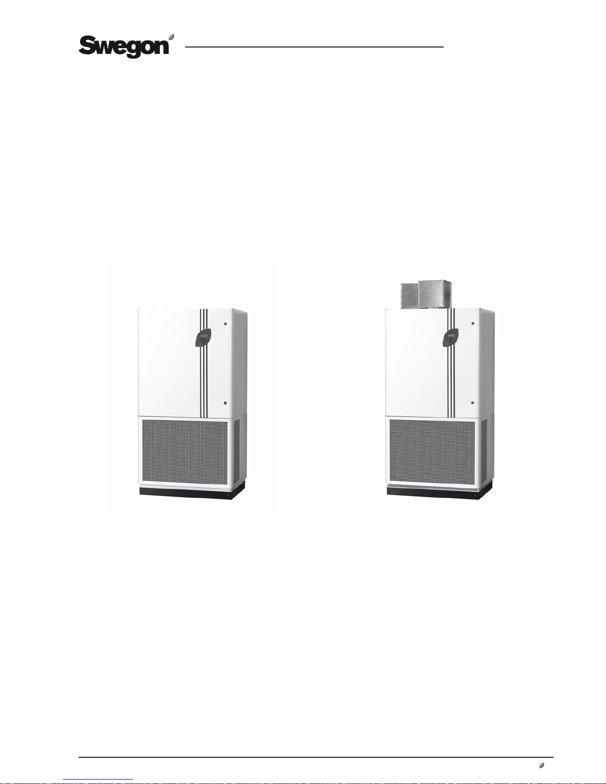
COMPACT AIR & COMPACT HEAT
Applicable to program version 1.04 and newer versions
COMPACT Heat
COMPACT Air
Page 2

GB.COMPACTAH.101110
Registered design. The company reserves the right to make design changes without prior notice.
2
www.swegon.com
Content
1 GENERAL .................................... 3
1.1 Field of Application ..................................3
1.2 Mechanical Design ...................................3
1.3 Control System ........................................3
1.4 Environmental Documentation .................3
1.5 The Components of the
Air Handling Units ..........................................4
1.5.1 COMPACT Air ....................................4
1.5.2 COMPACT Heat ..................................5
2 SAFETY PRECAUTIONS ..............6
2.1 To Start/Stop the Air Handling Unit ...........6
2.2 Risks .......................................................6
3 INSTALLATION ........................... 7
3.1 General ....................................................7
3.2 Transport Within the Site/Sectionalizing ....7
3.2.1 To Split the Air Handling Unit into
Separate Sections to Facilitate Transport
Within the Building Site. ..............................7
3.3 Location ...................................................8
3.4 To Fit the Kick-protection Base ..................8
3.5 To Install the Air Recirculation Section/
Louvre Damper
(applies to COMPACT Heat only) .... 8
3.6 Duct Connection ......................................8
3.7 Exterior Wall Hood ...................................9
3.8 Existing Ventilation ...................................9
3.9 Serving More than One Room ..................9
3.9.1 Extract Air Intake ................................9
3.9.2 Transfer Air ........................................9
3.10 Connection to the Electric Power Grid ....9
3.11 To Connect External Cables ....................9
3.12 To Adjust the Supply Air Discs ...............10
4 COMMISSIONING ....................11
4.1 General ..................................................11
5 CONTROL DISPLAY AND
USING THE MENU ....................... 12
5.1 Control display .......................................12
5.1.1 General: ...........................................12
5.1.2 The Buttons ......................................12
5.1.3 Display screen ...................................12
5.1.4 Abbreviations Used ...........................12
6 MAIN MENU 1 .......................... 13
6.1 The Menu Tree .......................................13
6.2 General ..................................................14
6.3 Selection of Language ............................14
6.4 Normal Operation ..................................14
6.5 Extended operation ................................14
6.6 Airing ....................................................14
6.7 Heating(applies to COMPACT Heat only) 14
6.8 Heating + Recirculation(applies to
COMPACT Heat only) ...................................14
6.9 Main Menu 2 .........................................14
7 MAIN MENU 2 .......................... 15
7.1 Menu tree ..............................................15
7.2 Changing Operating Mode ....................16
7.3 Settings .................................................16
8 USER LEVEL ..............................17
8.1 Temperature...........................................17
8.1.1 Readings ..........................................17
8.1.2 Settings ............................................17
8.2 Air fl ow/Pressure ....................................18
8.2.1 Readings ..........................................18
8.2.2 Settings ............................................18
8.3 Switch clock ...........................................19
8.4 Filters .....................................................19
8.4.1 Readings ..........................................19
8.4.2 To Calibrate the Filters ......................19
8.4.3 Calibration - Rotary Heat Exchanger ..19
8.5 Air Adjustment .......................................20
8.6 Alarms ...................................................20
9 INSTALLATION LEVEL ..............21
9.1 Menu Survey ..........................................21
10 FUNCTIONS ............................ 22
10.1 Temperature.........................................22
10.2.1.1 ERS Regulation ............................23
10.2.2 Airing Function ...............................24
10.2.2.1 Automatic Airing .........................24
10.2.2.2 Manual Airing .............................24
10.2.3 Summer Night Cooling ...................25
10.2.4 Intermittent Night-time Heating
(applies to COMPACT Heat only) ................26
10.2.5 Morning BOOST
(applies to COMPACT Heat only) ................27
10.2.6 Heating
(applies to COMPACT Heat only) ................27
10.2.7 External Temperature Sensors .........28
10.3 Flow/Pressure .......................................29
10.3.1 Fan Regulation ...............................29
10.3.1.1 Flow Regulation ...........................29
10.3.1.2 Demand Regulation (Control) ......29
10.3.1.3 Slave Control ...............................29
10.3.1.4 Clean Air Control .........................30
10.3.2 Outdoor Temperature
Compensation ...........................................31
10.3.3 Downspeed Control of Fan
Speed to Min. Set Point, Airfl ow ................32
10.4 To Activate the Filter
Monitoring Function ....................................32
10.5 Operation ............................................33
10.5.1 Switch clock ...................................33
10.5.2 Extended Operation ........................33
10.5.3 Summer time/Winter time ..............33
10.6 Heating ................................................34
10.6.1 Heat exchanger ..............................34
10.6.1.1 Defrosting the rotary heat
exchanger .................................................34
10.6.1.2 Heating BOOST
(applies to COMPACT Heat only) ................35
10.7 Cooling (Applies to an air cooler installed
in the outdoor air duct only) .........................36
10.7.1 Operation .......................................36
10.7.2 Temperature Regulation (Control) ...36
10.7.3 Periodic Operation ..........................37
10.7.4 Regulation Speed ...........................37
10.7.5 Outdoor Temperature Limit .............37
10.7.6 Restart Time ...................................37
10.7.7 Cooling Min Air Flow ......................37
10.7.8 Neutral Zone ..................................37
10.7.9 Cooling BOOST ..............................37
10.8 Input/output connections .....................38
10.9 IQnomic Plus ........................................39
11 AUTOMATIC FUNCTIONS ......40
11.1 General ................................................40
11.1.1 Starting Sequence ..........................40
11.1.2 Cooling Recovery ............................40
11.1.3 Zero Point Calibration .....................40
11.1.4 Additional cooling –
Electric Air Heater ......................................40
11.1.5 Additional running -
Heat Exchanger .........................................40
11.1.6 Density-corrected Airfl ow ...............40
11.1.7 BOOSTER-function
(Applies to COMPACT Heat only) ...............40
12 READINGS .............................. 41
13 MANUAL TEST ....................... 41
14 ALARM SETTINGS ..................42
14.1 Fire Alarms ...........................................42
14.2 External Alarms ....................................42
14.3 Alarm Limits .........................................42
14.4 Alarm Priority .......................................42
15 CONTROL DISPLAY ................43
15.1 Language .............................................43
15.2 Air fl ow unit .........................................43
15.3 Min/Max Adjustment ...........................43
15.4 Base Settings ........................................43
16 COMMUNICATION ................. 44
16.1 EIA-485 ...............................................44
16.2 Ethernet ...............................................44
17 SERVICE LEVEL .......................44
18 MAINTENANCE ...................... 45
18.1 Filter Change .......................................45
18.1.1 To remove the Filters .......................45
18.1.2 To fi t new fi lters ..............................45
18.2 Cleaning and Inspection .......................45
18.2.1 General ..........................................45
18.2.2 Filter Space .....................................45
18.2.3 Heat exchangers .............................45
18.2.4 Fans and Fan Space ........................45
18.3 Performance Checks ............................45
18.4 Damper Actuator for the Change-over
Damper .......................................................45
19 ALARMS AND
FAULT TRACING ..........................46
19.1 General ................................................46
19.1.1 A and B Alarms ...............................46
19.1.2 To reset the alarm ...........................46
19.1.3 To Change the Alarm Settings .........46
19.2 Alarm Descriptions with
Factory Settings ...........................................47
20 INFORMATIVE MESSAGES .... 51
21 TECHNICAL DATA ..................52
21.1 Dimensions, COMPACT Air...................52
21.2 Dimensions, COMPACT Heat ................52
21.3 Electrical Equipment Cubicle ................53
21.3.1 Internal Connections,
COMPACT Air ...........................................54
21.3.2 Internal Connections,
COMPACT Heat .........................................55
21.3.3 Connection to Terminal Blocks ........56
21.4 Electrical Data ......................................57
21.4.1 Air Handling Unit ............................57
21.4.2 Fans ...............................................57
21.4.3 Electrical equipment cubicle ............57
21.4.4 Heat Exchanger Motor ....................57
21.4.5 Control Inaccuracy ..........................57
22 APPENDICES ........................... 58
22.1 Compliancy Declaration .......................58
22.2 Commissioning Record .........................59
Page 3

GB.COMPACTAH.101110
Registered design. The company reserves the right to make design changes without prior notice.
www.swegon.com 3
1 GENERAL
1.1 Field of Application
The COMPACT Air and COMPACT Heat units are complete
air handling units that can be installed directly in the room
to be ventilated. The ducts for outdoor air and exhaust air
should be connected to the top of the unit and should be
arranged to lead out through the wall. Other than that,
you need only connect the unit to the mains electric supply.
The installation work can be carried out very quickly and
easily and if the task of cutting openings through the wall
is not complicated, the unit can be operational in just a
few hours. It is also simple to relocate the air handling
unit if the nature of the activities conducted in the room
changes.
The ventilation is very effective thanks to the displacement
air distribution method used. The built-in control equipment has several functions for economic operation.
The COMPACT Air and COMPACT Heat units are designed
for comfort ventilation and can be used in classrooms, day
nurseries, conference halls, smaller offi ces, workrooms,
shops, restaurants and similar public premises.
The difference between the COMPACT Air and the COMPACT Heat units is that the COMPACT Heat units can also
be used for heating.
It is important keep all the special characteristics of the
air handling units in mind when planning them into the
project, installing, adjusting and operating them to fully
obtain all the benefi ts the COMPACT system has to offer.
The unit must be installed indoors.
Important!
Always read the safety precautions in Section 2 that
explain the risks involved in running the unit and
designate who shall be permitted to operate and
service the unit, and carefully follow the installation
instructions provided in each paragraph.
The product identifi cation plates are located inside the
room unit and on the unit’s rear side. See Sections 1.5.1
and 1.5.2 respectively. Refer to the particulars on the
product identifi cation plate when you contact Swegon.
1.2 Mechanical Design
The COMPACT is available in one physical size and for two
airfl ow ranges.
Its sheet steel exterior is painted white, NCS S 0502-G.
The decorative strips and cover plate around the control
display are dark grey, NCS S6010-R90B. The inner skin is
predominantly made of aluminium-zinc plated sheet steel.
The casing has 30 mm thick intervening mineral wool
insulation; the inspection doors have 50 mm thick insulation.
The COMPACT Air and the COMPACT Heat are equipped
with pleated, Class F7 fi lters.
The type RECOnomic rotary heat exchanger is variable
speed controlled and has a peak temperature effi ciency of
85%.
The supply air and extract air fans are direct-driven plug
fans. The fans are equipped with EC motors that provide
high effi ciency across the entire operating range.
1.3 Control System
The IQnomic control system is microprocessor-based and is
integrated into the unit. It controls and regulates the fans,
heat exchanger, temperatures, airfl ows, operating times
and a large number of internal and external functions as
well as alarms.
1.4 Environmental Documentation
Environmental Documentation with the Dismantling
Instructions for recycling and the Environmental Declaration can be downloaded from our home page: wwww.
swegon.com.
The air handling unit is design in such a way that it can
be dismantled into its natural parts for scrapping. When
the unit has ended its useful product life, the services of
an accredited recycling company should be utilized for
disposal.
Approximately 94% of the parts in COMPACT air handling
units is recyclable.
Swegon AB is associated with the REPA Register, No.
5560778465.
Contact Swegon AB, Phone: +46 (0)512-322 00, if you
have any questions regarding the dismantling instructions
or the air handling unit’s impact on the environment.
Page 4
GB.COMPACTAH.101110
Registered design. The company reserves the right to make design changes without prior notice.
4 www.swegon.com
1.5 The Components of the
Air Handling Units
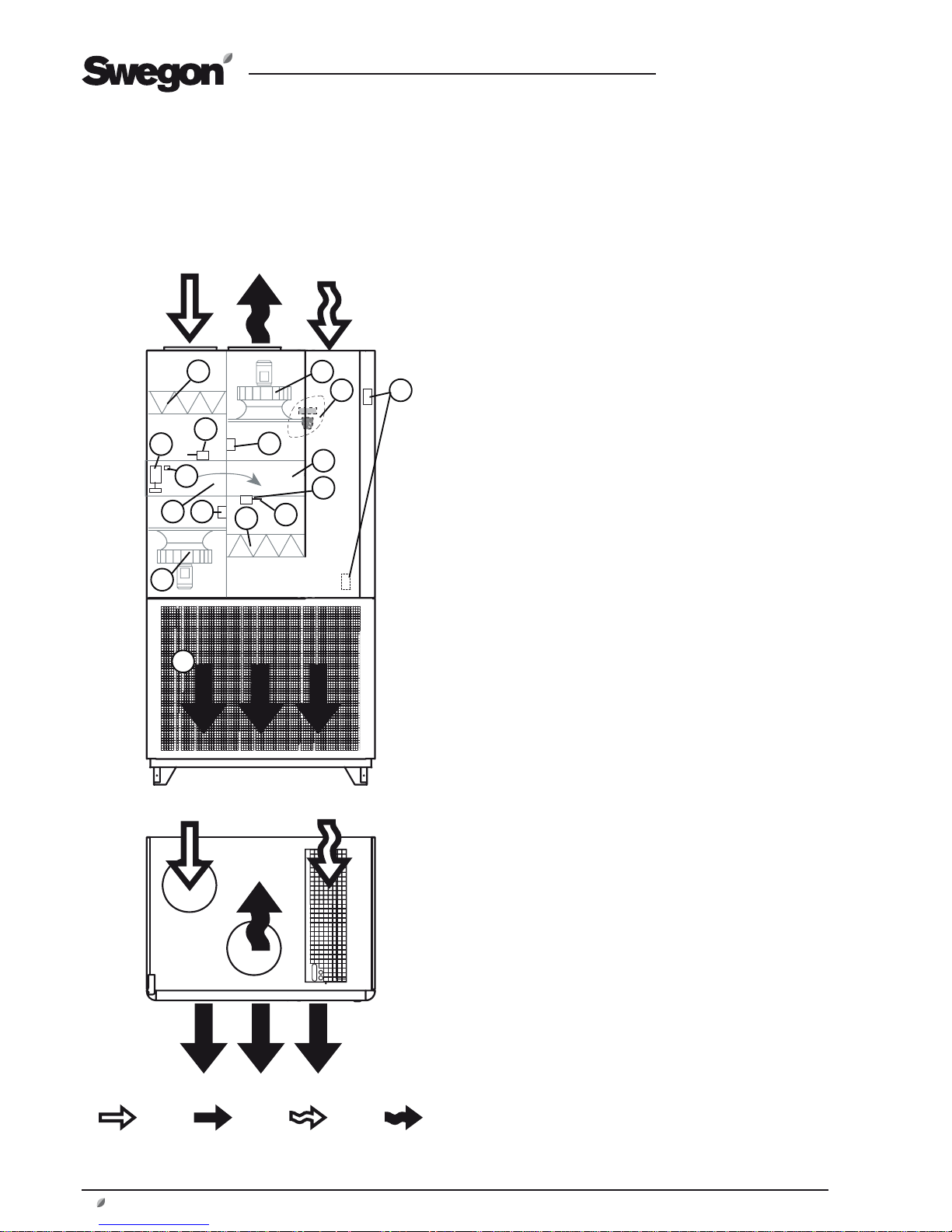
1.5.1 COMPACT Air
The individual components each specifi ed below in a simplifi ed and diagrammatical description.
The arrangement of the components
and their designations
1 Extract air fan with motor and built-in controller
2 Control display (on the inspection door)
3 Product identifi cation plate
4 Pressure sensor, extract air fan
5 Electrical equipm. cubicle with control unit
6 VOC sensor
7 Sensor, extract air temperature
8 Extract air fi lter
9 Sensor, supply air temperature (inside the lower section)
10 Supply air fan with motor and built-in controller
11 Heat exchanger
12 Pressure sensor, supply air fan
13 Sensor, rotation monitor
14 Drive motor, heat exchanger
15 Sensor, outdoor temperature
16 Supply air fi lter
Outdoor air Supply air Extract air Exhaust air
1
4
5
2
8
9
16
15
11
14
13
12
7
10
3
6
Page 5

GB.COMPACTAH.101110
Registered design. The company reserves the right to make design changes without prior notice.
www.swegon.com 5
1.5.2 COMPACT Heat
The individual components each specifi ed below in a simplifi ed and diagrammatical description.
The arrangement of the components
and their designations
1 Extract air fan with motor and built-in frequency inverter
2 Control display (on the inspection door)
3 Product identifi cation plate
4 Pressure sensor, extract air fan
5 Electrical equipm. cubicle with control unit
6 VOC sensor
7 Sensor, extract air temperature
8 Extract air fi lter
9 Electric air heater, (inside the lower section)
10 Sensor, supply air temperature (inside the lower section)
11 Change-over damper with actuator (inside the lower section)
12 Supply air fan with motor and built-in controller
13 Heat exchanger
14 Pressure sensor, supply air fan
15 Sensor, rotation monitor
16 Drive motor, heat exchanger
17 Sensor, outdoor temperature
18 Supply air fi lter
19 Recirculation section with actuator
20 Louvre damper
Outdoor air Supply air Extract air Exhaust air
1
4
5
2
8
18
13
16
15
14
12
3
19 20
10
17
7
11
9
6
Page 6
GB.COMPACTAH.101110
Registered design. The company reserves the right to make design changes without prior notice.
6 www.swegon.com
2 SAFETY PRECAUTIONS
All staff concerned must acquaint themselves with these
instructions before beginning any work on the unit. Any
damages to the unit or parts of it due to improper handling or misuse by the purchaser or the fi tter cannot be
considered subject to guarantee if these instructions have
not been followed correctly.
Warning
Only an authorised electrician or qualifi ed service
personnel trained by Swegon shall be permitted to
carry out electrical installation on the air handling
unit or wire external functions to it.
2.1 To Start/Stop the Air Handling Unit
The air handling unit should normally be started and
stopped via the control display. Note that the control
equipment of the air handling unit is still electrifi ed after
the unit has been switched off via the control display.
Pull out the plug connector before servicing the unit if not
otherwise specifi ed in the pertinent instructions or in the
event of an emergency.
2.2 Risks
Warning
Before carrying out any work, make sure that the
power supply to the air handling unit has been
isolated.
Risk areas with moving parts
Typical moving parts are fan impellers and drive pulleys of
the rotary heat exchanger. Safety guards are provided in
front of these components. If the ducts are not connected
to the fan outlet, these must be fi tted with a safety guard
(wire mesh screen).
Only a qualifi ed electrician or trained service technicians
shall be allowed to remove the safety guards.
Page 7
GB.COMPACTAH.101110
Registered design. The company reserves the right to make design changes without prior notice.
www.swegon.com 7
3.1 General
The air handling unit is delivered with packaging, standing
on a wooden pallet. The kick-protection base is supplied
in kit form laying inside a carton placed in the extract air
duct of the air handling unit. The recirculation section and
louvre damper, if ordered, are supplied unmounted. For
assembly instructions see Section 3.5.
Any accessories that have been ordered with the unit are
supplied in unmounted condition.
3.2 Transport Within the Site/Sectionalizing
The Compact Air unit is always supplied as one complete air handling unit. If transporting the unit within the
site proves diffi cult, the unit can be split into sections as
described below:
1. Open the inspection door using the spanner supplied with
the unit.
2. Dismantle the safety guard in front of the heat exchanger.
Disconnect the communication cable of the control display
by removing the quick connector on the control unit connection (marked HMI) and bundling strap. Pull the communication cable out all the way to the inspection door.
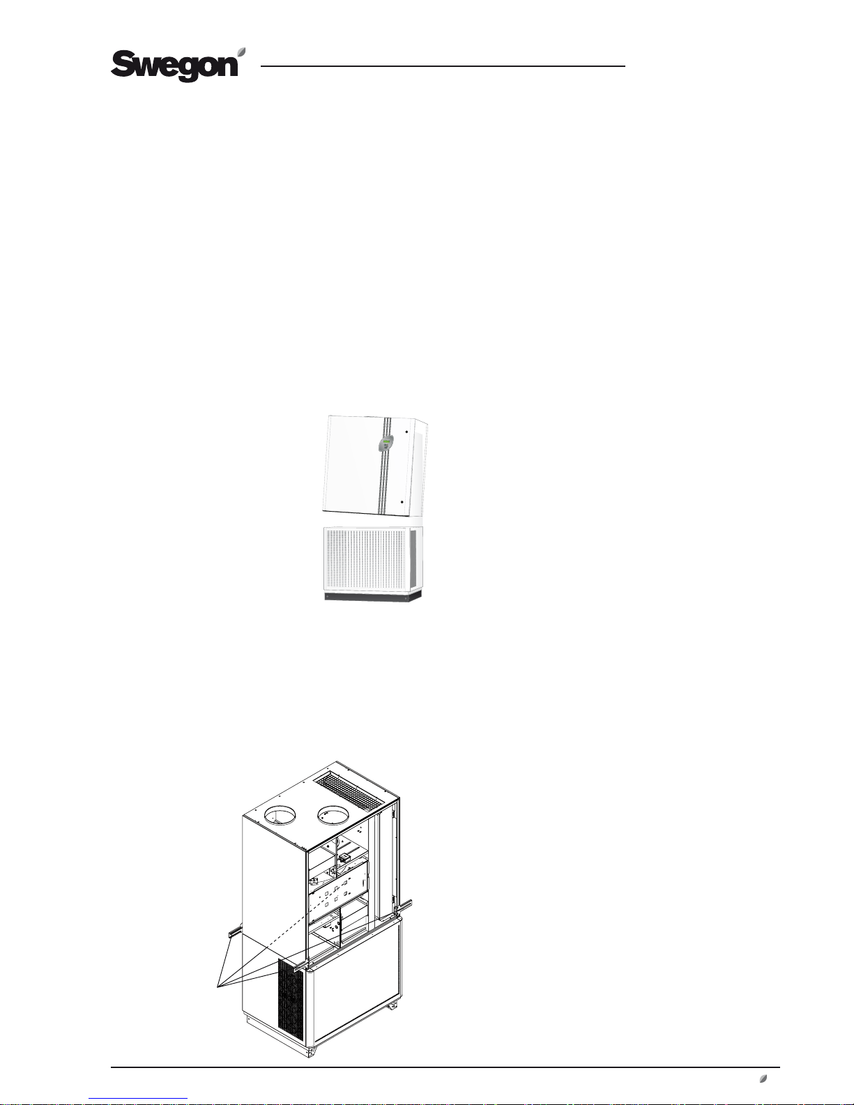
3.2.1 To Split the Air Handling Unit into Separate Sections to Facilitate Transport
Within the Building Site.
3 INSTALLATION
3. Remove the screws of the upper hinge and lift off the
inspection door.
4. Fasten the lifting handle (supplied, located below the extract
air fi lter) with screws, see illustration.
5. Remove the insulation and the safety guard from the supply
air fan.
6. Pull the quick connectors of the cables to the supply air fan
apart to disconnect them.
7. Dismantle the supply air fan by backing off the two screws
in the rear part of the fan suspension bracket. Do not
unscrew them completely. Unscrew and remove the screws
in the front part of the suspension bracket. Withdraw the
entire fan package. The suspension bracket will then let go
from the rear screws.
8. Slightly turn the fan package and withdraw it from the unit.
9. If you need to further reduce the weight of the upper section, you can also dismantle the extract air fan by repeating
Items 5-8 above.
10. Remove the cable protection on the bottom of the fan compartment.
11. If the air handling unit is fi tted with an electric air heater,
unscrew the screws of this component, lift it up and place it
loosely inside the air handling unit.
12. Remove the screws that secure the mounting bracket of
the supply air sensor. Lift up the mounting bracket and the
supply air sensor and place them to rest unsecured inside
the unit.
13. Remove the four screws (M8) in the bottom of the upper
section. These screws hold both sections together.
14. Lift off the upper section.
15. Now each section can be individually transported.
16 Reassembly should be carried out following the above steps
in the reverse order.
3.2.2 To Remove the Door and Front Grille
1. Remove the safety guard in front of the heat exchanger.
2. Disconnect the communication cable of the control display
by removing the quick connector on the control unit connection (marked HMI) and bundling strap. Pull the communication cable out all the way to the inspection door.
3. Remove the screws of the upper hinge and lift off the
inspection door.
4. Remove the four screws that hold the front grille of the
upper section, using a 6 mm Allen wrench.
5. Reassembly should be carried out following the above steps
in the reverse order.
Lifting handles,
(set of 4)
Page 8
GB.COMPACTAH.101110
Registered design. The company reserves the right to make design changes without prior notice.
8 www.swegon.com
3.5 To Install the Air Recirculation Section/
Louvre Damper
(applies to COMPACT Heat only)
The room temperature sensor supplied with the unit must
be mounted, see special instructions for the TBLZ-1-24-2
room sensor.
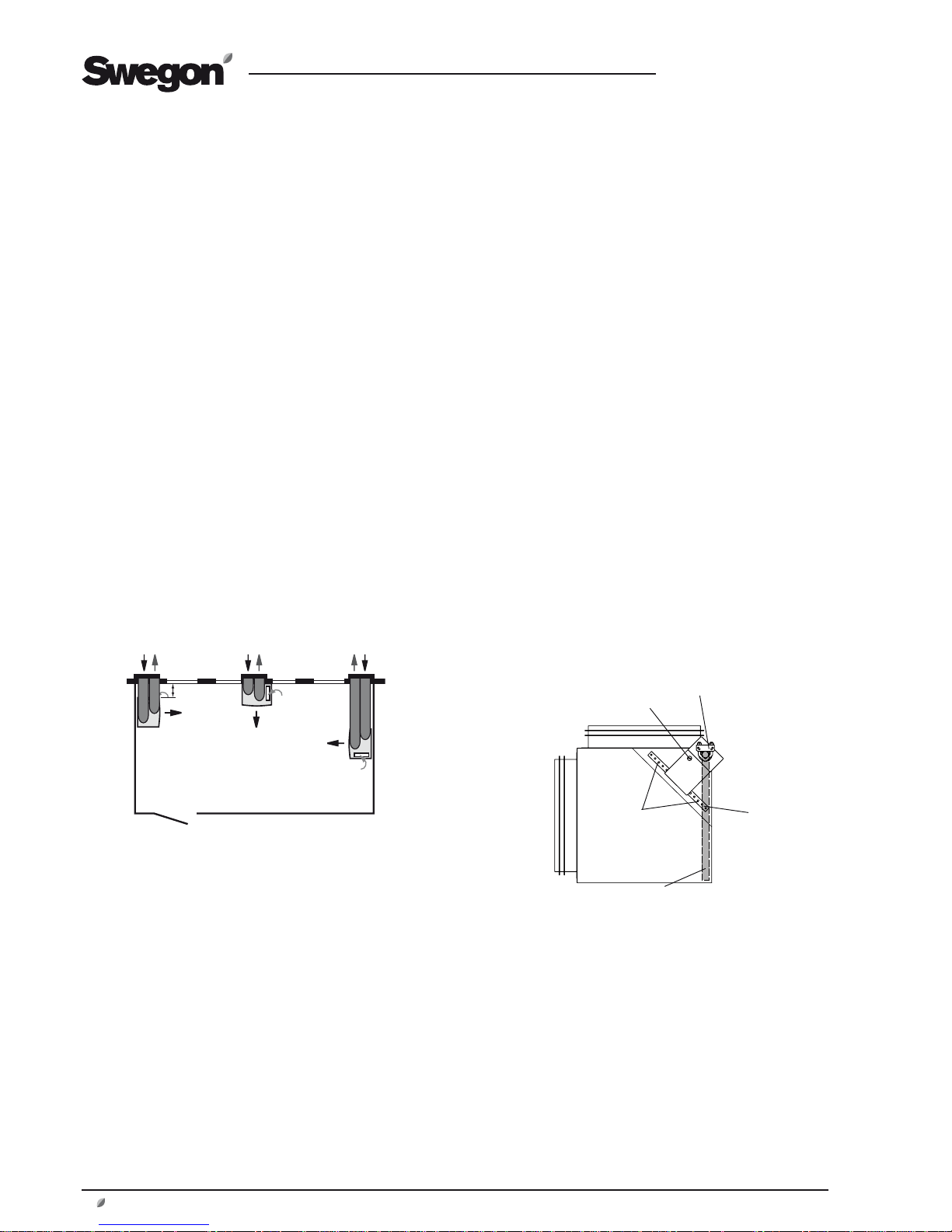
The air recirculation section and louvre damper are supplied loose.
The damper actuator for the air recirculation section is
supplied resting on the extract air intake mesh on top of
the unit. This part must be mounted on the air recirculation section’s damper spindle as follows:
1. Remove the damper actuator from the mesh of the extract
air intake. It is advisable to mount the damper
actuator while the air recirculation section is at fl oor level
before the former is mounted.
2. Disconnect the electric quick connector on the damper
actuator.
3. Secure the mounting rail by means of the screws provided,
in the redrilled holes on the air recirculation section. See
illustration.
3. Mount the damper actuator with the damper blade in the
outdoor air position, that is: the damper blade must be
located against the grille. See illustration.
4. Tighten the screws holding the damper actuator with the
clamp on the damper spindle. Set the actuating direction
according to the direction arrow towards 0. See illustration.
5. Mount the air recirculation section on the top side of the air
handling unit for outdoor air and connect the electric quick
connector.
6. Fit the louvre damper on the top side of the air handling
unit for exhaust air.
3.6 Duct Connection
Connect 250 mm dia. spiral ducts to the outdoor air and
exhaust air connections on the top side of the air handling
unit.
Run the ducts through the external wall and have the duct
end edge-to-edge with the façade of the building if Swegon’s external wall hood is used.
The ducts can also be run through the ceiling (the ducts
for the COMPACT Heat cannot be run straight up from
the air handling unit. However this makes more complicated modifi cations necessary and among others places
greater demands on sealing around the arrangement to
achieve air tightness.
The ducts must be insulated with at least 30 mm thick
insulation and be provided with a damp-proof outer layer.
3.3 Location
To achieve optimal operating economy it is important to
design the duct system with as low a pressure drop as possible. Therefore the designer should focus on arranging
the duct runs as short as possible so that there will not be
more duct bends than necessary. The duct connections on
the Compact Air/Heat units are arranged to enable ducts
to be run in any direction without being in the way of one
another.
The design of the hoods, grilles, etc. for outdoor air/exhaust air are also important. The specially constructed
exterior wall hood for the Compact Air/Heat units is designed in such a way that minimizes pressure losses.
Examples of alternative locations of the Compact Air/Heat
unit in a room are shown below.
Important! The air handling unit should be located
at least 400 mm on either side from a wall to avoid
acoustic problems. See the illustration below.
For the sake of comfort, the nearest workplace should be
1 metre from the unit. However note that at least 1,200
mm open space is required in order to be able to open the
inspection door.
In the case of a COMPACT Heat unit, make sure that you
provide open space in front of the air handling unit to enable long throw lengths when the unit is operating in the
BOOSTER mode (fl ow Boost).
3.4 To Fit the Kick-protection Base
Secure the 6 screws supplied halfway into the tapped
holes on the base beam of the air handling unit.
Then fi t the side plates of the kick protection base (the
two short plates) by pushing the keyhole fasteners over
the screws from the front side of the unit. Now the side
plate should hang loosely on the screws.
Fit the front side of the kick protection plate (the long
plate) on the two screws on the front side. Now the front
plate should hang loosely on the screws.
Adjust the position of the plates and tighten the screws.
Fasten the cover plugs, supplied, in the holes over the
screws.
Important! If the unit is to be installed with its right-hand
or left-hand side near a wall (min. of 400 mm), the base
plate that is to face this way should be fi tted before the
unit is positioned at its fi nal location.
Mounting rail
Damper blade must be in the outdoor air position (grey-shaded)
Clamp for the damper spindle must be in this position
Actuating direction in Position 0
Air recirculation
section
Min.
400 mm
Predrilled
holes
Page 9
GB.COMPACTAH.101110
Registered design. The company reserves the right to make design changes without prior notice.
www.swegon.com 9
3.7 Exterior Wall Hood
The CACZ-1-03 External wall hood accessory is specially
designed for low pressure drop and for preventing shortcircuiting between the outdoor air and the exhaust air.
The standard hood is painted grey black, NCS 8502-B. See
special instructions.
3.8 Existing Ventilation
The existing ventilation in the room for supply air and
extract air should be blanked off or sealed. This is an
important prerequisite for satisfactory ventilation and heat
recovery.
3.9 Serving More than One Room
The COMPACT Air units are designed for installation and
connection according the instructions in Sections 3.3, 3.6
and 3.7.
Swegon recommends this procedure.
Nevertheless it is possible to completely or partially take
extract air from adjacent rooms or also to ventilate a space
other than the room where the air handling unit is standing.
The problems, which one must observe in this case, are
specifi ed below. Always engage the services of a professional in this fi eld.
3.9.1 Extract Air Intake
If the extract air is completely or partially taken from an
adjacent room, note that the duct pressure drop must not
exceed available pressure.
Also note that the supply air temperature is regulated in
relation to the extract air temperature. If the extract air
comes from another room with a different temperature,
the temperature of the supply air may cause short-circuit
airfl ows or give rise to draught problems. Pay special attention to where the extract air sensor is located.
3.9.2 Transfer Air
Transfer air grilles to adjacent rooms have a strong infl uence on the system’s performance.
Air transfer grilles positioned low, cause the transfer of
”unused” air to adjacent rooms and impair the ventilation
performance in the room where the unit is installed.
Air transfer grilles positioned high involve the risk that
”used” air will be transferred to adjacent rooms. Ventilation is however not impaired in the room where the unit is
installed.
Important! If the doors are open, the adjacent room will
also be ventilated due to the displacing air supply.
3.10 Connection to the Electric Power Grid
The COMPACT air handling unit is supplied with a power
cable with mains plug, from the factory.
COMPACT Air
Cable: 3 x 1.5 mm2. Mains plug, 10 AT, single-phase 230V.
COMPACT Heat
Cable: 5 x 2.5 mm2. Mains plug, 5-wire Perilex, 16 AT,
3-phase 400V.
Important! The power supply connection to the COMPACT Heat unit is not of an electrical safety design that
prevents children from inserting objects into the socket. It
is recommended that it be positioned 2 metres above the
fl oor above the air handling unit by the duct connections
for instance.
If the air handling unit is instead to be connected with a
fi xed extension, an external main switch must be fi tted.
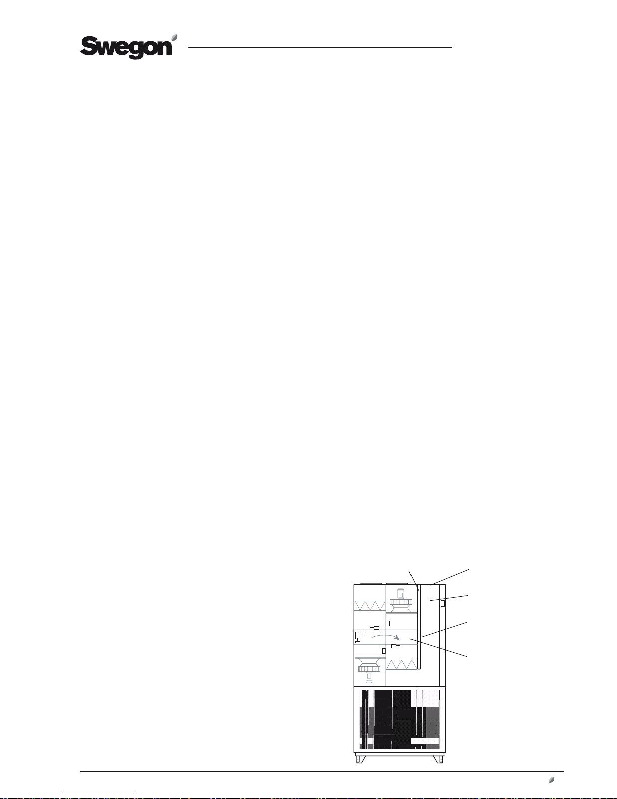
3.11 To Connect External Cables
The electrical cubicle in the COMPACT Air and the COMPACT Heat units is located by the heat exchanger. When
access to the control unit is required, the safety guard
in front of the heat exchanger must fi rst be dismantled.
When access to the power unit is required, the cover plate
in the unit’s extract air duct must fi rst be dismantled.
Cables from external sources can be run into the air handling unit through the rubber diaphragm by the extract air
intake, located on the top of the unit.
The external cables can be extended in the existing cable
protection together with the power supply cable in the
extract air duct of the unit. Insert the cable in the opening
in the end of the cable protection or press it in between
the cable protection and the insulation.
Cables can be run in to the electric cubicle according to
appropriate hole instructions in the rubber diaphragm.
N.B.! Cables for external communication outside the air
handling unit must be arranged at a minimum distance of
100 mm from any current-carrying (live) cable.
Electrical equipment cubicle
Extract air duct of the
air handling unit
Extract Air Intake
Cable protection
Cover plate
Page 10
GB.COMPACTAH.101110
Registered design. The company reserves the right to make design changes without prior notice.
10 www.swegon.com
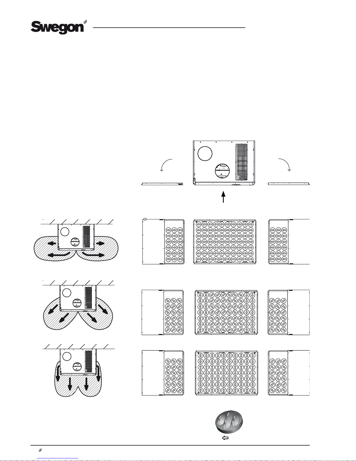
3.12 To Adjust the Supply Air Discs
The positions of the supply air discs can be adjusted after
dismantling the front grille of the lower section of the
unit. Use a 6 mm Allen key. The screws are located within
the outer holes in the corners.
When the front grille has been removed, the air discharge
direction of the front discs can be adjusted from the
backside of the front grille. Turn the discs by hand to the
appropriate setting.
The side discs can now also be adjusted without any further dismantling. The discs are accessible by putting your
hand inside the air handling unit.
Air handling unit viewed from above.
The front discs and side discs are
shown from this view below.
The factory-preset supply air distribution pattern and two
examples of possible modifi ed distribution patterns are
shown below.
Since each disc is individually adjustable, the possibilities
for modifying the air distribution pattern are practically
endless.
The arrows shown above
indicate the position of
each disc.
Discs in factory-preset position
Distribution pattern
Example 1
Example 2
Front discs and side discs
Page 11

GB.COMPACTAH.101110
Registered design. The company reserves the right to make design changes without prior notice.
www.swegon.com 11
4 COMMISSIONING
4.1 General
Commissioning sequence:
1. Check that there are no foreign objects inside the unit,
duct system or functional sections.
COMPACT Heat: air recirculation section, louvre
damper and room temperature sensor shall be installed,
see Section 3.5.
2. Connect the mains plug. Note that the air handling
unit starts up immediately and operates in the normal
mode.
3. Select the appropriate language, if you have not already
done so. See Section 15.1.
4. The air handling unit has a factory setting that makes
it ready to operate. See Section 22.2 Commissioning
Record.
However, in many cases, these settings need to be
adjusted to suit the current installation.
Program the timer (switch clock), operating mode,
temperatures, airfl ows and functions according to the
procedures in Sections 6-17.
Select whether the airfl ow unit of measurement shall
be l/s, m3/s or m3/h. (INSTALLATION LEVEL in the CONTROL DISPLAY menu).
Fill out the Commissioning Record and save it in the
document pocket of the air handling unit.
5. Activate, if needed, manual or auto operation (MAIN
MENU 2) or lock the speed of the fans (AIR ADJUSTMENT menu).
6. Finish off with a fi lter calibration as described in Section
6.4.2.
Page 12
GB.COMPACTAH.101110
Registered design. The company reserves the right to make design changes without prior notice.
12 www.swegon.com
5 CONTROL DISPLAY AND
USING THE MENU
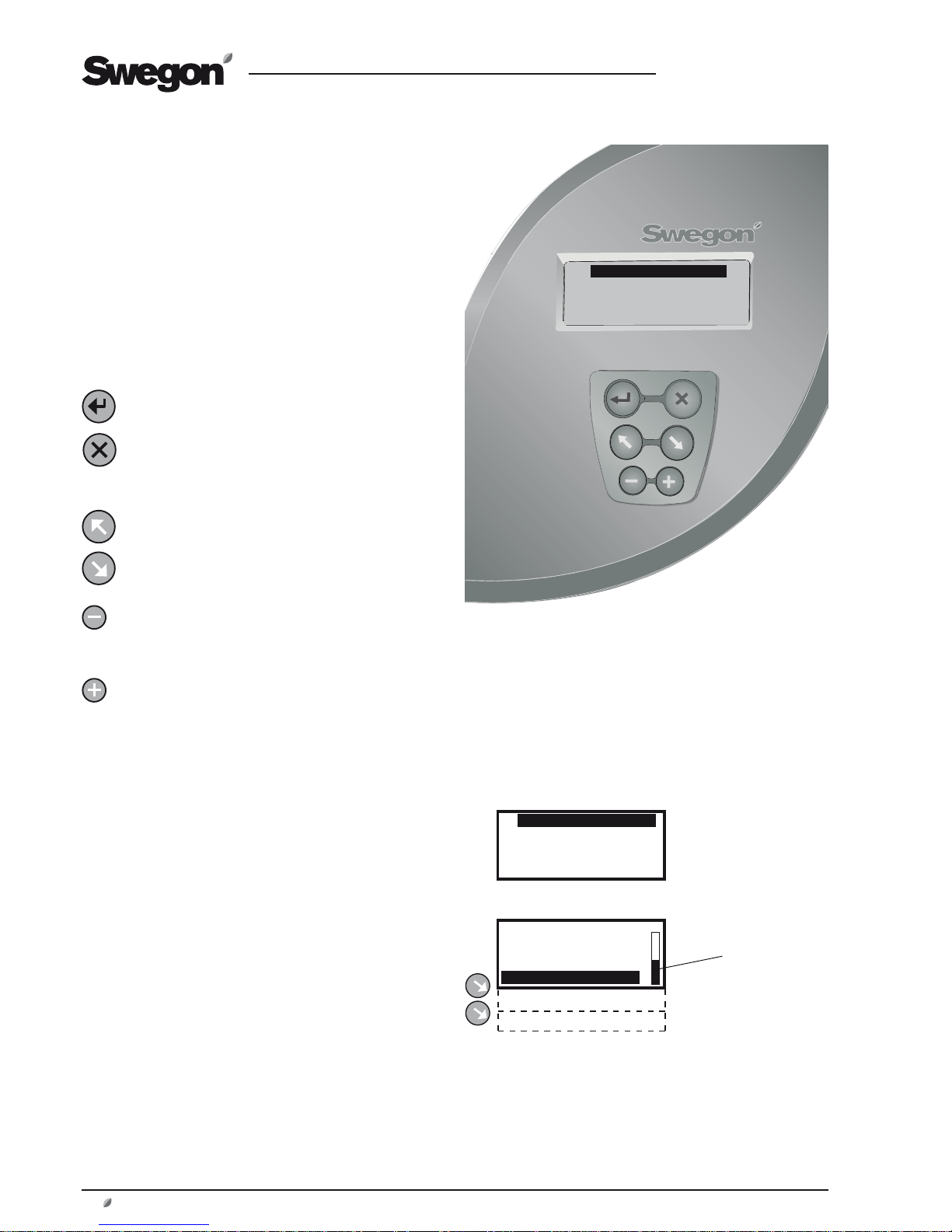
5.1 Control display
5.1.1 General:
The control display has an illuminated display, 6 pushbuttons and a red LED for indicating alarms.
5.1.2 The Buttons
The buttons have the following functions:
ENTER confi rms your selection of the highlighted
function and proceeds to next deeper menu level.
ESCAPE changes the display back to the previous
menu. For menus with REMAIN.TIME display, the
image changes automatically back to the previous
menu after approx. 10 seconds.
ADVANCE UPWARD or to the LEFT.
ADVANCE DOWNWARD or to the RIGHT.
DECREASES the value of the highlighted setting.
Changes are registered immediately and need not
be confi rmed by pressing Enter.
INCREASES the value of the highlighted setting.
Changes are registered immediately and need not
be confi rmed by pressing Enter.
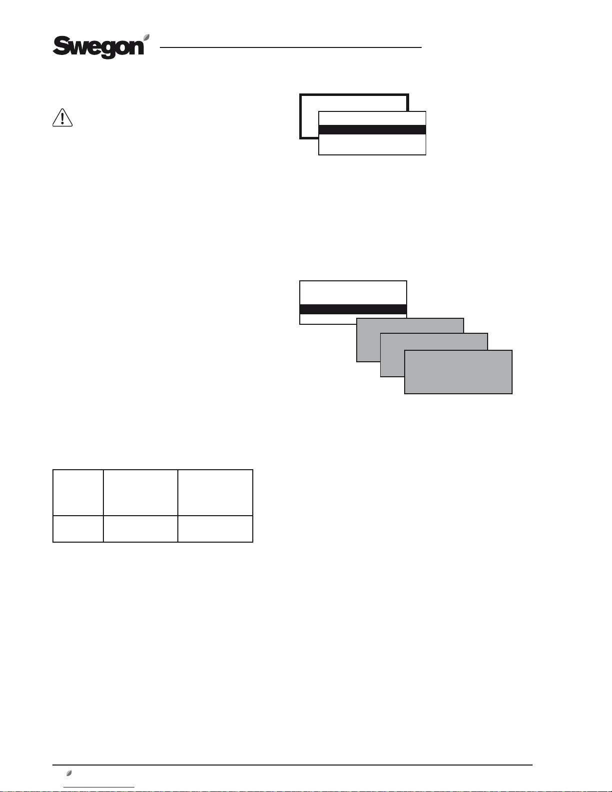
5.1.3 Display screen
The display screen has 4 lines. Many of the menus however have more lines and these are shown line for line as
you press the ADVANCE DOWNWARD button. The position indicator shows where you are in the menu.
5.1.4 Abbreviations Used
The following abbreviations are generally used in the
menus:
SA = Supply air (Ex: SA FAN = Supply air fan)
EA = Extract air
OUTD = Outdoor air
ROOM = Room
ANTI-FROST MON = Anti-frosting monitor
HEAT EXCH = Heat exchanger
The control display is mounted on the
inspection door of the air handling unit.
Position indicator
√ NORMAL OPERATION
EXTENDED OPERATION
AIRING
>>
COMPACT-A TUE 14:40
STOP
MANUAL OPERATION
STOP?
MAN/AUTO.OP
SETTINGS
√ NORMAL OPERATION
EXTENDED OPERATION
AIRING
>>
Page 13
GB.COMPACTAH.101110
Registered design. The company reserves the right to make design changes without prior notice.
www.swegon.com 13
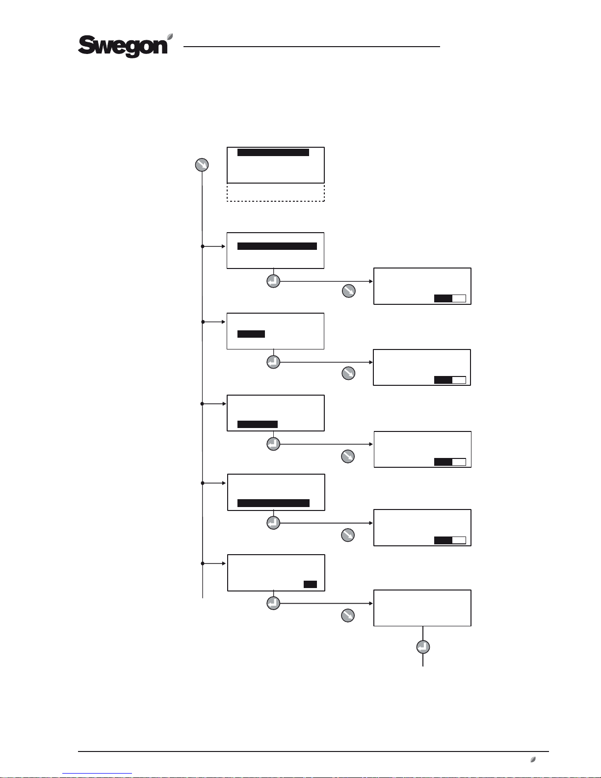
6 MAIN MENU 1
6.1 The Menu Tree
Code = 1110*
To Main Menu 2
* The code can be changed under Service Level.
√ NORMAL OPERATION
EXTENDED OPERATION
AIRING
HEATING
HEATING + RECIRC.
>>
NORMAL OPERATION
√ EXTENDED OPERATION
AIRING
HEATING
NORMAL OPERATION
EXTENDED OPERATION
√ AIRING
HEATING
NORMAL OPERATION
EXTENDED OPERATION
AIRING
√ HEATING
EXTENDED OPERATION
AIRING
HEATING
√
HEATING + RECIRC.
Applies to COMPACT Heat only
Applies to COMPACT Heat only
AIRING
HEATING
HEATING + RECIRC.
>>
EXTENDED
LOW SPEED
REM.TIME
AIRING
REM.TIME
VÄRMNING
HEATING
REM.TIME
VÄRMNING
HEATING + RECIRC.
REM.TIME
VÄRMNING
CODE: 0000
Page 14

GB.COMPACTAH.101110
Registered design. The company reserves the right to make design changes without prior notice.
14 www.swegon.com
6.2 General
The main menu is normally shown if no other menu has
been selected.
The display automatically returns to the main menu after
30 minutes.
The content in the menu changes depending on the
operating mode selected, other functions that affect the
present operating mode and possible tripped alarms.
6.3 Selection of Language
When the air handling unit is started up for the fi rst time,
a language selection menu is displayed. Select the appropriate language.
If you want to change language at a later opportunity – or
if you’ve selected the wrong language – you can change
the language at INSTALLATION LEVEL under CONTROL
DISPLAY. See Section 15.1.
6.4 Normal Operation
NORMAL OPERATION is highlighted in the display when
the air handling unit is operated in the selected operating mode under Main Menu 2. Alternatives to operation
are: stop (appears alternately in the menu when selected),
auto operation, manual low speed or manual high speed
operation, see Section 7.2.
The type of operation selected can be checked under Main
Menu 2.
Normal operation indicates that the air handling unit is not
being operated in any of the time-limited manually activated functions. See Sections 6.5, 6.6, 6.7 and 6.8.
6.5 Extended operation
When EXTENDED OPERATION has been activated, the
unit operates in the high speed airfl ow mode preset under
User Level, see Section 8.2.
For particulars of the times for extended operation, see
Section 10.5.2.
The function can be cancelled by pressing the escape
button on the control display and then selecting Normal
Operation.
6.6 Airing
When AIRING is activated, the unit operates in the max
speed airfl ow mode preset under User Level, see Section
8.2.
For particulars on how to set the appropriate supply air
temperature and period for airing, see Section 10.2.2.
The function can be cancelled by pressing the escape
button on the control display and then selecting Normal
Operation.
6.7 Heating
(applies to COMPACT Heat only)
The COMPACT Heat can be used for heating the room.
When HEATING is activated, the electric air heater (7.5
kW) heats up the air. A change-over damper in the lower
section of the air handling unit is reset and the air is led to
the air discharge outlets at the bottom of the unit. The air
is discharged at high velocity and follows the fl oor surface
by means of the so-called coanda effect. This enables long
throw lengths and quickly heats the entire premises.
The function can also be manually selected under HEATING. The air handling unit then operates According to the
preset conditions and times, see Section 10.2.6.
The function can be cancelled by pressing the escape
button on the control display and then selecting Normal
Operation.
6.8 Heating + Recirculation
(applies to COMPACT Heat only)
The COMPACT Heat can be used for heating the room.
When the HEATING + RECIRC. function is activated, the
extract air fan and the heat exchanger are switched off.
The damper in the air recirculation section is reset and
room air is circulated. The louvre damper for exhaust air
closes to prevent any cold down draught.
The electric air heater (7.5 kW) heats up the air. A changeover damper in the lower section of the air handling unit
is reset and the air is led to the air discharge outlets at the
bottom of the unit. The air is discharged at high velocity
and follows the fl oor surface by means of the so-called
coanda effect. This enables long throw lengths and quickly
heats the entire premises.
When HEATING + RECIRC. is activated the air handling
unit operates according to the preset conditions and
times, see Section 10.2.6.
The function can be cancelled by pressing the escape
button on the control display and then selecting Normal
Operation.
6.9 Main Menu 2
You can access to Main Menu 2 by highlighting >> the
line farthest down and acknowledge by pressing the Enter
button.
Enter the code. (Factory-preset code: 1110) The code can
be changed under Service Level.
Page 15
GB.COMPACTAH.101110
Registered design. The company reserves the right to make design changes without prior notice.
www.swegon.com 15
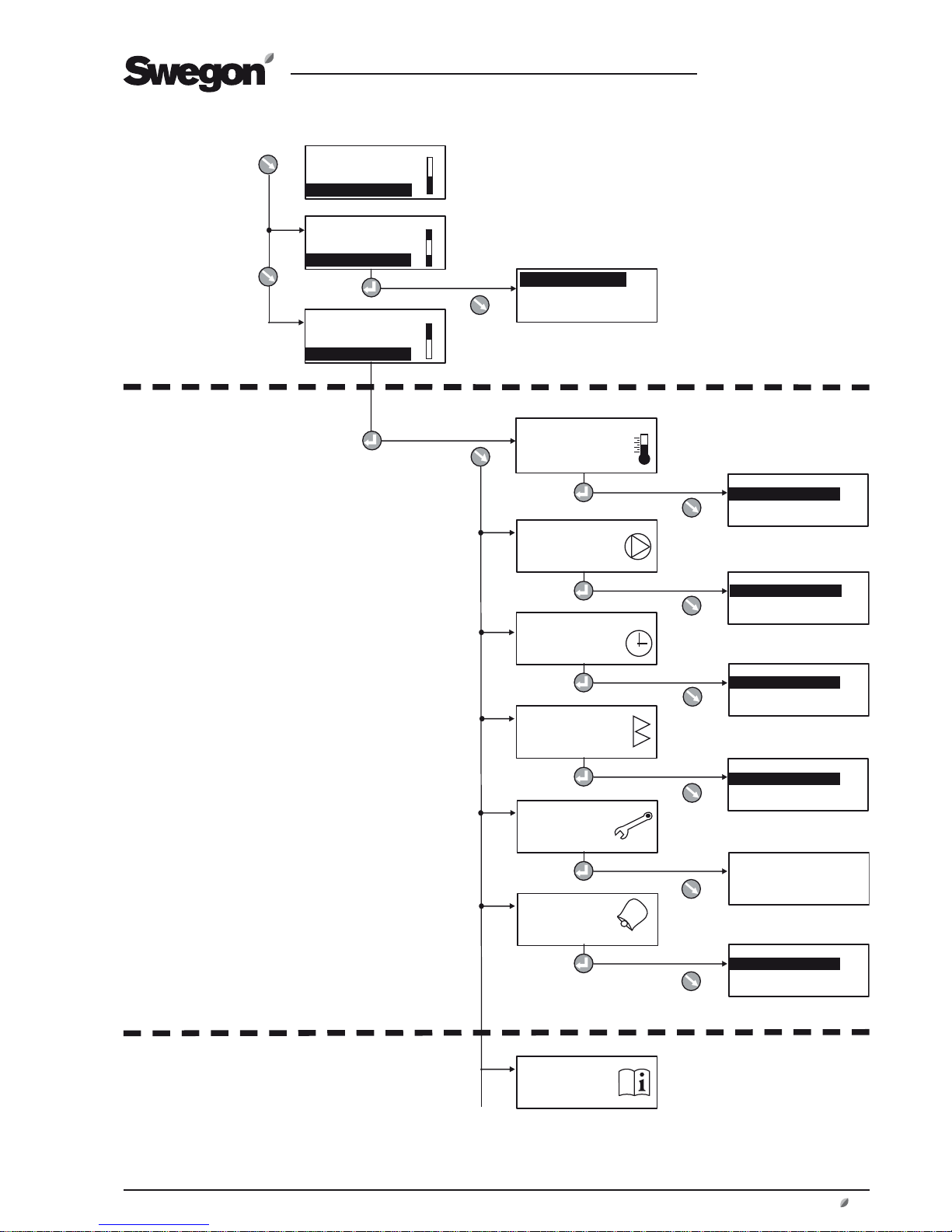
7 MAIN
MENU 2
7.1 Menu tree
USER LEVEL
(Section 8)
INSTALLATION LEVEL
(Section 9-17)
COMPACT-A TUE 14:40
STOP
MANUAL OPERATION
STOP?
COMPACT-A TUE 14:40
MANUAL OPERATION
STOP?
MAN/AUTO.OP
COMPACT-A TUE 14:40
STOP?
MAN/AUTO.OP
SETTINGS
TEMPERATURE
FLOW/PRESSURE
SWITCH CLOCK
FILTERS
AIR ADJUSTMENT
ALARMS
INSTALLATION
AUTO OPERATION
MANUAL LOW SPEED
MANUAL HIGH SPEED
*SWITCH CLOCK*
TIME/DATE
TIME CHANNEL
YEAR CHANNEL
*FILTERS*
READINGS
CALIBRATION
*AIR ADJUSTMENT*
LOCKS FAN SPEED
TIME SETTING: 0 h
*ALARMS*
ACTIVE ALARMS
ALARM HISTORY
*FLOW/PRESSURE*
READINGS
SETTINGS
Important! The appearance of
the menus varies depending
on the type of air handling
unit and functions selected.
*TEMPERATURE*
READINGS
SETTINGS
Page 16
GB.COMPACTAH.101110
Registered design. The company reserves the right to make design changes without prior notice.
16 www.swegon.com
COMPACT-A TUE 14:40
STOP
MANUAL OPERATION
STOP?
COMPACT-A TUE 14:40
MANUAL OPERATION
STOP?
MAN/AUTO.OP
AUTO OPERATION
MANUAL LOW SPEED
MANUAL HIGH SPEED
COMPACT-A TUE 14:40
STOP?
MAN/AUTO.OP
SETTINGS
USER LEVEL
INSTALLATION LEVEL
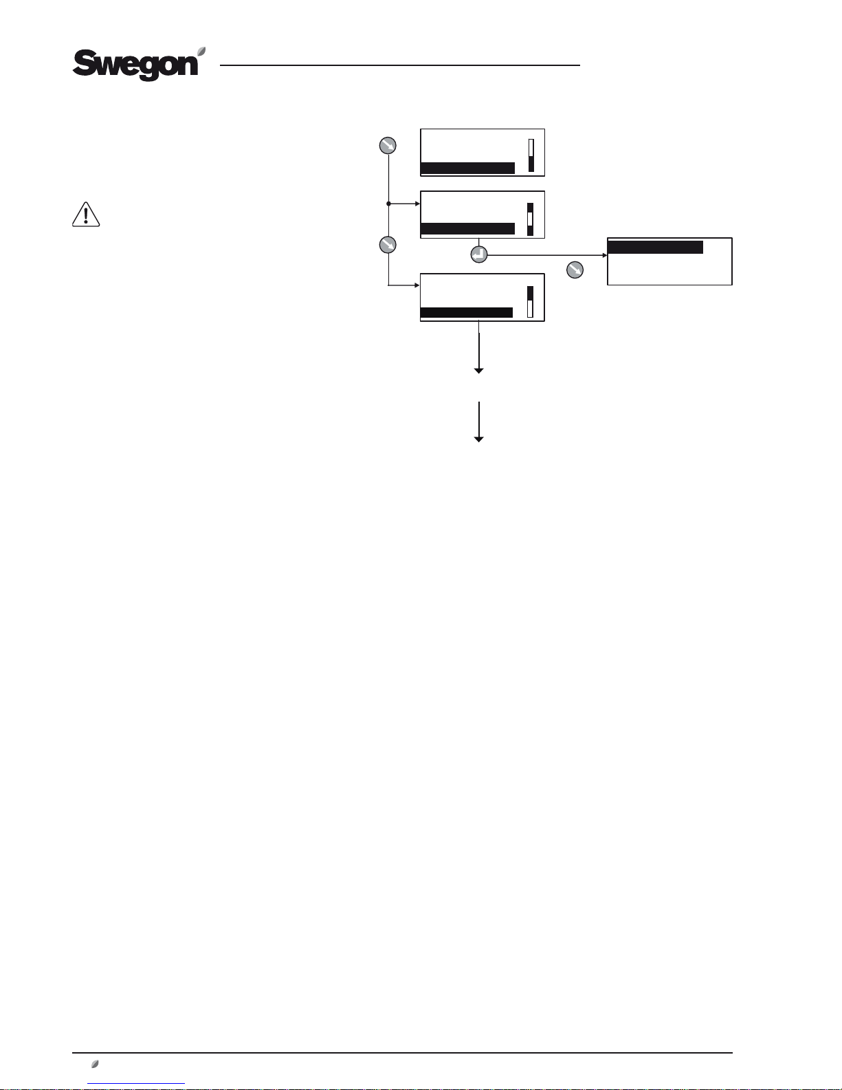
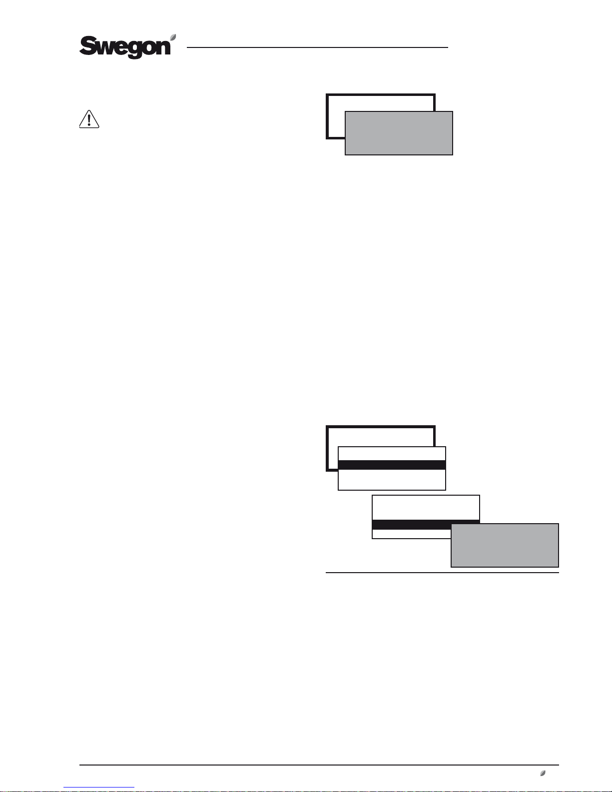
7.2 Changing Operating Mode
You can start and stop the air handling unit or
change over to manual or automatic operation
from the main menu.
The air handling unit should normally be
started and stopped from the hand-held
micro terminal; not by switching the safety
isolating switch on and off.
When the air handling unit is started up, menus
for the various delays that are part of the starting
sequence are shown.
See also Section 11.1.1, Starting Sequence.
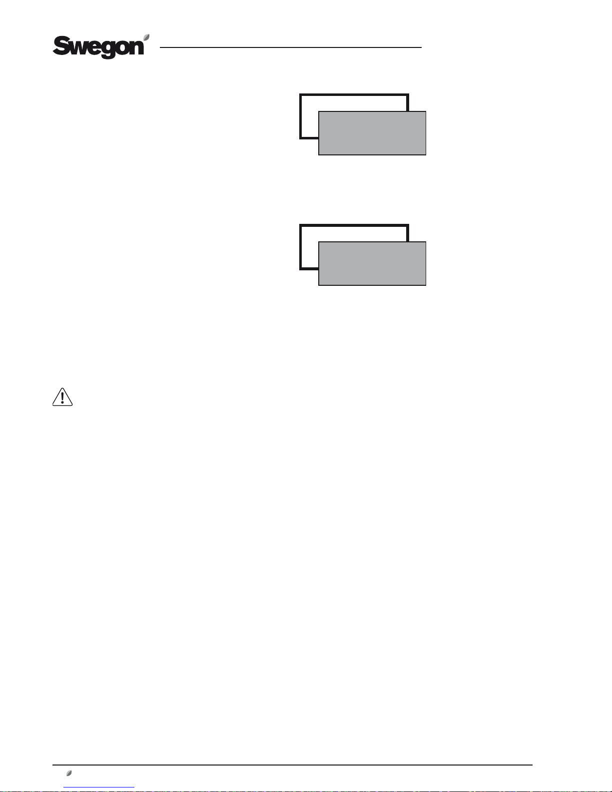
7.3 Settings
When selecting SETTINGS in the main menu, you
will advance to User Level and Installation Level.
See Section 8.
Page 17
GB.COMPACTAH.101110
Registered design. The company reserves the right to make design changes without prior notice.
www.swegon.com 17
8 USER LEVEL
8.1 Temperature
The basic functions can be preset at INSTALLATION LEVEL and the values can be read and set at USER LEVEL.
See also Section 10.2 in which the functions for
temperature are described in detail.
IMPORTANT! If you intend to substantially alter the tempera-
ture settings, you should fi rst stop the air handling unit before
doing so.
8.1.1 Readings
Used for checking the performance.
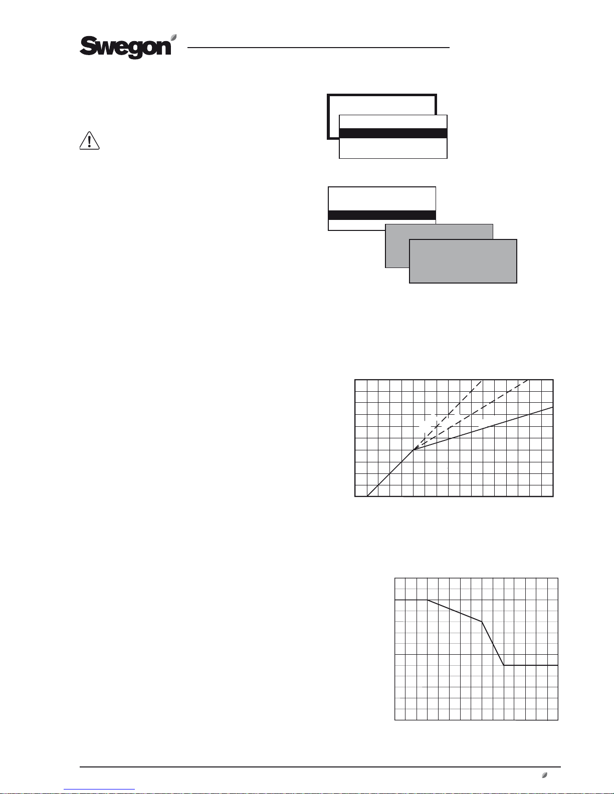
8.1.2 Settings
ERS REGULATION 1
The control unit regulates the relationship between the supply air and the extract air temperatures according to a factory
preset curve.
Settings (see the chart to the right as well):
Value Setting Factory
range settings
Step 1 - 3 1
EA/SA Differential 1-5 °C* 2 °C
Breakpoint (refers to 15-23 °C* 20 °C
extract air temperature)
*) The setting range can be changed. See Section 15.3, Min./
Max. Setting.
ERS REGULATION 2
The control unit regulates the relationship between the supply
air and extract air temperatures according to a custom-plotted
curve. The curve has three adjustable breakpoints.
Settings (see the chart to the right as well):
Value Setting Factory
range settings
Extract air temperature
X1 10-40 °C 15 °C
X2 10-40 °C 20 °C
X3 10-40 °C 22 °C
Supply air temperature
Y1 10-40 °C 20 °C
Y2 10-40 °C 18 °C
Y3 10-40 °C 14 °C
ERS Regulation 1
TEMPERATURE
*TEMPERATURE*
READINGS
SETTINGS
*TEMPERATURE*
READINGS
SETTINGS
ERS REGULATION 1
ERS REGULATION 2
Important! The
appearance of the menus
varies depending on the
type of air handling unit
and functions selected.
15 16 17 18 19 20 21 22 23 24 25 26 27 28 29 30 31 32
15
16
17
18
19
20
21
22
23
24
14
Supply air temperature setpoint °C
Extract air temperature °C
Step 3
Step 2
Step 1
1
2
3
15
20
22
9
10
12 15 20 25 27
X = Extract air temperature °C
Y = Supply air temperature setpoint °C
ERS Regulation 2
Page 18
GB.COMPACTAH.101110
Registered design. The company reserves the right to make design changes without prior notice.
18 www.swegon.com
8.2 Air fl ow/Pressure
Basic functions are set at INSTALLATION LEVEL
and values are read and set at USER LEVEL.
Therefore see also Section 10.3, in which the func-
tions for fl ow/pressure are described in detail.
8.2.1 Readings
Used for performance checks.
8.2.2 Settings
The functions selected at INSTALLATION LEVEL and the
min. and max. airfl ows of each unit size (see the table
below) determine which values can be set.
Values for airfl ow (l/s, m3/s, m3/h), pressure (Pa) or input
signal strength (%) can be preset depending on the function selected.
LOW SPEED
Must always be preset! The value for low fan speed cannot be higher than the value for high speed.
Low speed can be set as 0, which means that the air handling unit stops.
HIGH SPEED
Must always be preset! The value for high speed cannot
be lower than the value for low speed.
MAX SPEED
Is only appropriate for the airing function. The value for
max speed cannot be lower than the value for high speed.
AIRFLOW MIN FLOW
COMPACT AIR AND
COMPACT HEAT
MAX FLOW
COMPACT AIR AND
COMPACT HEAT
SIZE
m3/h * m3/s m3/h m3/s
02 300 0.08 800 0.23
03 300 0.08 1300 0.36
* When you adjust the value, round off the value to the nearest
adjustable step.
Min/Max Airfl ows
AIR FLOW/PRESSURE
*FLOW/PRESSURE*
READINGS
SETTINGS
*FLOW/PRESSURE*
READINGS
SETTINGS
LOW SPEED
HIGH SPEED
MAX. SPEED
Page 19
GB.COMPACTAH.101110
Registered design. The company reserves the right to make design changes without prior notice.
www.swegon.com 19
8.3 Switch clock
Basic functions for the switch clock can be preset
at INSTALLATION LEVEL under FUNCTIONS/OPERATION and the values can be read and set at USER
LEVEL.
TIME/DATE
The current date and time can be set and adjusted whenever
required.
The switch clock automatically takes leap years into consideration.
Automatic changeover between summer time/winter time to EU
Standard has been preset.
This changeover function can be blocked at INSTALLATION LEVEL
under FUNCTIONS/OPERATION
.
TIME CHANNEL
Times and days can be set when the unit is to run at high speed,
low speed or be stopped.
Eight different time channels can be set. If the same in-operation
times are to apply every day of the week (Mon-Sun), you need
only program one time channel. Different operation times for
each day of the week can be programmed by programming a
time channel for each day (Mon-Fri, Sat-Sun or Mon, Tues, Wed,
etc)
The time can be set as 00:00-00:00 if the deviating in-operation
period is desirable for the entire 24 hours period.
YEAR CHANNEL
The year channels make it possible to set deviating in-service
times for parts of the day during certain parts of the year. Eight
different year channels (yearly time schedules) can be set. The
year channels over-modulate the time channel during the hours
of the day and the days that the year channel is active. The year
channel dates indicate the dates between which the year channel shall apply and the year channel hours indicate the hours of
the day between which the year channel will steer the controller
to operate the rotary heat exchanger at a specifi ed speed. Other
times within the year channel still apply to that time channel.
The time can be set as 00:00-00:00 if the deviating in-operation
period is desirable for the entire 24 hours period.
Functions for summer night cooling, prolonged operation, etc.,
operate also when the year channel is active.
8.4 Filters
(and anti-frosting function of rotary heat exchanger)
There are two types of fi lter monitoring:
Calculated fi lter monitoring (preset at factory) monitors the fan’s
speed increase conditional on the degree of fouling in the fi lter.
The calibration involves taking airfl ow and fan speed readings.
An alarm is initiated when the fan speed has increased by 10%
above the preset alarm limit.
Filter monitoring with a pressure sensor (accessory) measures
the pressure drop across the fi lter. The alarm limit is preset in Pa.
8.4.1 Readings
When reading the fi lter status, the fi rst value shows current value
and the second value shows current alarm limit.
8.4.2 To Calibrate the Filters
The fi lters must be calibrated for the fi rst time during commissioning, when the duct system has been installed and adjusted.
After that every time fi lters are replaced.
Calibration should be activated for both the supply air and the
extract air if both fi lters are changed or for only for one airfl ow
direction if only one fi lter has been changed.
When fi lter calibration has been activated, the unit runs at high
speed for about 3 minutes.
After the fi lter has been calibrated, a speed increase of 10%, or
a pressure rise (= fouling of the fi lters) of 100 Pa is permissible,
after which an alarm is initiated indicating a fouled fi lter.
The alarm limit can be changed at INSTALLATION LEVEL under
ALARM SETTINGS.
8.4.3 Calibration - Rotary Heat Exchanger
If the anti-frosting function accessory for heat exchanger is installed (see 10.6.1.1) calibration can be selected from this menu.
When calibration R-HX is activated the fans are accelerated to
high speed for about 3 minutes.
SWITCH CLOCK
*SWITCH CLOCK*
TIME/DATE
TIME CHANNEL
YEAR CHANNEL
Settings:
Value Setting Factory
range setting
TIME/DATE
Day Mon-Sun Automatic
Time 00:00-23:59 Current
Date Day/Month/Year Current
TIME CHANNEL 1-8
Operation Low speed/High speed* High speed
Time 00:00-23:59 00:00-00:00
Period Not active Not active
Mon, Tues, Wed etc
Mon-Fri
Mon-Sun
Sat-Sun
YEAR CHANNEL 1-8
Operation Not active Not active
Stop/Low sp./High sp.
Time 00:00-23:59 00:00-00:00
Period From Day/Month/Year 01/01/2005
To Day/Month/Year 01/01/2005
*) Shows Stop/Low speed/High speed if this function is selected
at INSTALLATION LEVEL under FUNCTIONS/OPERATION.
FILTERS
*FILTERS*
READINGS
CALIBRATION
*FILTERS*
READINGS
CALIBRATION
*FILTER CALIBRATION*
STD.FILTER
HEAT EXCHANGER
Page 20
GB.COMPACTAH.101110
Registered design. The company reserves the right to make design changes without prior notice.
20 www.swegon.com
8.5 Air Adjustment
The speed of the fans can be locked for up to 72 hours.
This is practical in conjunction with adjusting the airfl ow in
the duct system.
The period desired is preset but can be interrupted earlier
by selecting STOP in the menu or by changing the time
setting to 0.
8.6 Alarms
If an alarm is initiated, this is shown in the hand-held terminal both as clear text and by a blinking red diode.
This menu enables you to read alarms quickly.
ACTIVE ALARMS
Shows alarms that are active but have not initiated an
alarm signal in the display. This applies to alarms that have
a long delay, i.e. airfl ow or temperature alarms.
ALARM HISTORY
The 10 most recent tripped alarms are shown.
Alarm settings can be entered at INSTALLATION
LEVEL under ALARM SETTINGS.
For complete description of alarms, see Section 19.
AIR ADJUSTMENT
*AIR ADJUSTMENT*
LOCKS FAN SPEED.
TIME SETTING: 0 h
ALARMS
*ALARMS*
ACTIVE ALARMS
ALARM HISTORY
Page 21

GB.COMPACTAH.101110
Registered design. The company reserves the right to make design changes without prior notice.
www.swegon.com 21
Section 10
Section 12
Section 13
Section 14
Section 15
Section 16
Section 17
FUNCTIONS
READINGS
MANUAL TEST
ALARM SET
CONTROL DISPLAY
COMMUNICATION
SERVICE LEV.
*MANUAL TEST*
TEMPERATURE
FANS
HEAT EXCHANGE
REHEAT
IN/OUTPUTS
IQnomic Plus
*READINGS*
TEMPERATURE
FANS
HEAT EXCHANGE
REGULATION SIGNALS
IN/OUTPUTS
IQnomic Plus
OPERATION TIME
PROGRAMVERSIONS
*ALARM SETTINGS*
FIRE ALARM
EXTERNAL ALARMS
ALARM LIMITS
ALARM PRIORITY
*CONTROL DISPLAY INST*
LANGUAGE
AIR FLOW UNIT
MIN/MAX SETTING
BASE SETTINGS
*COMMUNICATION*
EIA-485
ETHERNET
*SERVICE LEV.*
CODE: 0000
INSTALLATION
9 INSTALLATION LEVEL
9.1 Menu Survey
*FUNCTIONS*
TEMPERATURE
AIR FLOW/PRESSURE
FILTER
OPERATION
HEATING
COOLING
IN/OUTPUTS
IQnomic Plus
Section 11
Automatic functions
*INSTALLATION*
CODE: 0000
Code = 1111
Important! The appearance of
the menus varies depending
on the type of air handling
unit and functions selected.
Page 22

GB.COMPACTAH.101110
Registered design. The company reserves the right to make design changes without prior notice.
22 www.swegon.com
10 FUNCTIONS
10.1 Temperature
Basic functions can be set at INSTALLATION LEVEL
and values are read and set at USER LEVEL.
IMPORTANT! If you intend to substantially alter the temperature settings, you should fi rst stop the air handling
unit before doing so.
10.2 Temperature Regulation (Control)
Select ERS Regulation. Then select ERS Regulation 1 or 2.
Control sequence for ERS regulation:
1. The temperature effi ciency of the air handling unit’s
heat exchanger is modulated to provide max. heat
recovery.
2. After that the air heater, if installed, will begin to
generate heat.
3. If a downstream heating coil is not installed, or if the
its output is not adequate, the supply air fan will be
automatically and variably downspeed-regulated to
convey air at a lower fl ow rate.
A neutral zone can be preset, which allows a lower supply
air temperature setpoint before regulation to a lower fl ow
rate begins. See 10.3.3.
When the supply airfl ow is regulated to a lower rate, the
heat exchanger will have ”excess heat”, i.e. warm extract
air, giving it capacity to maintain the supply air temperature required.
As the supply airfl ow is regulated to a lower rate, the air
pressure in the premises will become negative and this
will instead cause outdoor air to be sucked in through
leakage spots such as doors and windows. This outdoor
air will then be heated by the usual heating system of the
premises.
Downspeed regulation to lower the airfl ow rate occurs
from the current preset fl ow (high speed or low speed),
down to half of this fl ow rate. The degree of regulation
to a lower rate is also limited by the min fl ow setting of
the unit. When preset fl ow for low speed is near the min
fl ow rate, the effect of this regulation to a lower rate will
be small.
INSTALLATION
FUNCTIONS
*FUNCTIONS*
TEMPERATURE
AIR FLOW/PRESSURE
FILTER
OPERATION
HEATING
COOLING
IN/OUTPUTS
IQnomic Plus
* Applies to COMPACT Heat
only
Important! The appearance
of the menus varies
depending on the type of air
handling unit and functions
selected.
* TEMPERATURE *
TEMPERATURE REG
AIRING FUNCTION
SUMMER NIGHT COOL
INTERM. NIGHT HEAT
MORNING BOOST
HEATING
EXT. SENSORS
*
*
*
Page 23

GB.COMPACTAH.101110
Registered design. The company reserves the right to make design changes without prior notice.
www.swegon.com 23
10.2.1.1 ERS Regulation
ERS regulation means Extract air temperature-Related
Supply air temperature regulation. This means that the
temperature of the supply air is regulated in relation to the
temperature of the extract air. Under normal circumstances, the supply air temperature is regulated to be a few degrees lower than the extract air temperature. In this way,
the heat exchanger will provide optimal performance, and
this means excellent operating economy. ERS regulation is
suitable for use when there is excess heat in the premises
generated, for example, by machinery, lighting or people
and the supply air devices in the premises are suitable for
diffusing air below room temperature.
ERS REGULATION 1
The control unit regulates the relationship between the
supply air and extract air temperatures according to a factory-preset curve.
See the chart to the right.
The steps, breakpoint and EA/SA differential plotted in
the curve can be changed at USER LEVEL under TEMPERATURE/SETTINGS.
Settings:
Value Setting Factory
range setting
Step 1 – 3 1
Breakpoint 15-23 °C 20 °C
(refers to extract air temp.)
EA/SA-Differential 1-5 °C 2 °C
The setting range for the Break Point and EA/SA difference is limited by Min. and Max. settings at INSTALLATION
LEVEL under CONTROL DISPLAY.
ERS REGULATION 2
This is used when special needs and conditions are such
that the factory preset ERS regulation 1 curve cannot provide the results required. Conditional on which settings are
made, it may be necessary to install a post-heating coil.
An individually adapted curve regulates the relationship
between the supply air and extract air temperature.
See the chart to the right.
The following settings are possible at USER LEVEL under
TEMPERATURE/SETTINGS:
Value Setting Factory
range setting
Extract air temperature
X1 10-38 °C 15 °C
X2 11-39 °C 20 °C
X3 12-40 °C 22 °C
Supply air temperature setpoint
Y1 10-40 °C 20 °C
Y2 10-40 °C 18 °C
Y3 10-40 °C 14 °C
Factory setting means:
If the extract air temperature is below 20 °C (breakpoint),
the supply air temperature setpoint will be automatically
regulated to be 2 °C (EA/SA differential) lower.
If the extract air temperature is above 20 °C, the supply
air temperature setpoint will follow the curve according to
Step 1.
Breakpoints according to factory setting means:
If the extract air temperature is below 15 °C (X1) the setpoint for supply air temperature is constant 20 °C (Y1).
If the extract air temperature is 20 °C (X2) the supply air
temperature set point will be 18 °C (Y2).
If the extract air temperature is above 22 °C (X3), the supply air temperature setpoint will be constantly 14 °C (Y3).
15 16 17 18 19 20 21 22 23 24 25 26 27 28 29 30 31 32
15
16
17
18
19
20
21
22
23
24
14
Supply air temperature setpoint °C
Extract air temperature °C
Step 3
Step 2
Step 1
ERS regulation 1
1
2
3
15
20
22
9
10
12 15 20 25 27
X = Extract air temperature °C
Y = Setpoint supply air temperature °C
ERS regulation 2
Page 24

GB.COMPACTAH.101110
Registered design. The company reserves the right to make design changes without prior notice.
24 www.swegon.com
10.2.2 Airing Function
The airing function means that the air handling unit will
operate in the max. speed mode and temperature during
the preset period.
The function requires either a presence detector or has to
be manually activated in Main Menu 1.
10.2.2.1 Automatic Airing
The presence detector shall be connected to the external
input, selected for external high speed.
Conditions that must be met for automatic airing to start:
• Presence of occupant(s) has been indicated during at
least 10 minutes.
• Occupant(s) are no longer present and the preset time
period for high speed airfl ow has expired.
Conditions that must be met for automatic airing to stop:
• Airing has taken place during the preset time period.
• The presence of occupant(s) is indicated via input for
externally actuated high speed airfl ow.
10.2.2.2 Manual Airing
The Airing function can be started from Main Menu 1 and
will then operate during the preset time period.
The Airing function can be manually cancelled by setting
the air handling unit to Normal Operation in the control
display.
Settings:
Value Setting range Factory setting
Function, Off/On Inactive/Active Inactive
Supply air temperature 10 - 20 °C 10 °C
Time period 10-60 min. 15 min.
INSTALLATION
FUNCTIONS
*FUNCTIONS*
TEMPERATURE
AIR FLOW/PRESSURE
FILTER
OPERATION
HEATING
COOLING
IN/OUTPUTS
IQnomic Plus
* Applies to COMPACT Heat
only
* TEMPERATURE *
TEMPERATURE REG
AIRING FUNCTION
SUMMER NIGHT COOL
INTERM. NIGHT HEAT
MORNING BOOST
HEATING
EXT. SENSORS
*
*
*
Page 25

GB.COMPACTAH.101110
Registered design. The company reserves the right to make design changes without prior notice.
www.swegon.com 25
10.2.3 Summer Night Cooling
The lower temperature at night is utilized to cool down
the building structure. This reduces the cooling load during the fi rst hours of the day. If a cooling unit is installed,
its in-operation hours will be minimized, thus offering savings. If no cooling unit is installed, a certain cooling effect
will still be realized.
When summer night cooling function is activated, the unit
fans operate at high speed, with a supply air setpoint of
10°C, from the preset time until the conditions necessary
for stop are satisfi ed.
Conditions to be met to start summer night cooling at the
preset time:
• The extract air temperature should be higher than the
preset value
• The extract air should be at least 2°C warmer than the
outdoor air.
• The outdoor temperature should be above the preset
value.
• Heating has not been required between 12.00–23.00
hours.
• The unit must not operate in the high speed mode or
be stopped from an external source or manually from the
control display.
Conditions to be met to stop summer night cooling at the
preset time:
• The extract air temperature drops below the preset
value.
• The outdoor temperature drops below the preset value.
• Switch clock or external input calls for high speed.
• The extract air is less than 1 °C warmer than the outdoor
air.
The function starts once per set time period.
Settings:
Value Setting Factory
range setting
Extract air temperature for start 17 - 27 °C 22 °C
Extract air temperature for stop 12 - 22 °C 16 °C
Outdoor temperature for stop 5 - 15 °C 10 °C
Supply air setpoint 10 - 20 °C 10 °C
Operating period 00:00-00:00 23:00-06:00
INSTALLATION
FUNCTIONS
*FUNCTIONS*
TEMPERATURE
AIR FLOW/PRESSURE
FILTER
OPERATION
HEATING
COOLING
IN/OUTPUTS
IQnomic Plus
* Applies to COMPACT Heat
only
* TEMPERATURE *
TEMPERATURE REG
AIRING FUNCTION
SUMMER NIGHT COOL
INTERM. NIGHT HEAT
MORNING BOOST
HEATING
EXT. SENSORS
*
*
*
Page 26

GB.COMPACTAH.101110
Registered design. The company reserves the right to make design changes without prior notice.
26 www.swegon.com
If the extract airfl ow is set to 0 and the output to the
damper is inactive, the following will take place:
When conditions for start are met, outdoor air and exhaust air shut-off dampers remain closed. The damper in
the air recirculation section is opened. The extract air fan
is idle.
The supply air fan operates according to the preset supply
airfl ow and the heating coil downstream of the air handling unit operates according to the supply air temperature setpoint, until the conditions for stop are met.
10.2.4 Intermittent Night-time Heating
(applies to COMPACT Heat only)
The unit is utilized to heat the premises when it is normally
stopped by the switch clock.
The function requires connection of an external room
sensor. Connect the TBLZ-1-24-2 Room sensor by means
of the modular cable supplied, to an optional connection
marked Internal BUS 1.
When the function is activated, the air handling unit detects when the room temperature drops below the preset
start temperature. The unit starts with preset fl ows and
the supply air temperature setpoint.
If extract air fan operation is not desirable, the extract
airfl ow can be set to 0.
The damper output can be set to be Inactive. This means
that the connected dampers (such as shut-off dampers
for outdoor air and extract air) will not be affected. These
dampers are normally closed when the air handling unit is
stopped and they also remain closed. The damper in the
air recirculation section opens at the same time.
Intermittent night-time heating does not affect a possible
extra temperature zone (Xzone) that regulates according
to its ordinary set point, if intermittent night-time heating
is in operation.
Conditions to be met for intermittent night-time heating
to start:
• The unit should operate in a time channel/switch clock
stop.
• The room temperature should be below set start tem-
perature.
Conditions to be met for intermittent night-time heating
to stop:
• High speed or external/manual stop should be activated.
• Room temperature should be above the preset stop
temperature.
• Alarm with preset stop priority has tripped.
If the needed, the air handling unit fans will continue to
operate to cool the electric air heater although other conditions for stop have been met.)
Settings:
Value Setting Factory
range setting
Room temperature for start 5 - 25 °C 16 °C
Room temperature for stop 5 - 25 °C 18 °C
Supply air temperature setpoint 10 - 40 °C 28 °C
Supply airfl ow *) m3/s/Pa **) m3/s/Pa
Extract airfl ow *) m3/s/Pa 0 m3/s/Pa
Damper output Inactive/Active Inactive
*) The setting range is the same as the min/max settings of the
air handling unit.
**) According to the setting for low speed at USER LEVEL under
FLOW/PRESSURE.
Intermittent night-time heating with air recirculation section:
INSTALLATION
FUNCTIONS
*FUNCTIONS*
TEMPERATURE
AIR FLOW/PRESSURE
FILTER
OPERATION
HEATING
COOLING
IN/OUTPUTS
IQnomic Plus
RUMSLUFT
SUPPLY AIR
* Applies to COMPACT Heat
* TEMPERATURE *
TEMPERATURE REG
AIRING FUNCTION
SUMMER NIGHT COOL
INTERM. NIGHT HEAT
MORNING BOOST
HEATING
EXT. SENSORS
*
*
*
Page 27

GB.COMPACTAH.101110
Registered design. The company reserves the right to make design changes without prior notice.
www.swegon.com 27
10.2.5 Morning BOOST
(applies to COMPACT Heat only)
The unit is utilised to heat the premises during a preset
period prior to the switch-in time set on the switch clock.
The unit starts early and uses the separate settings for
operation and temperature regulation.
The preset time is the time difference between the start of
Morning BOOST to the start of ordinary operation.
Damper output can be set to be inactive. This means that
connected dampers (e.g. outdoor air and exhaust air shutoff dampers) are not affected. Normally these dampers
are closed when the unit is stopped and thus they remain
closed. The damper in the air recirculation section opens
at the same time.
The extract airfl ow can be set to Inactive if it is not desirable for the extract air fan to operate.
Settings:
Value Setting Factory
range setting
Time for start prior to regular
start time according to switch clock hour, min.
00:00
Damper output Inactive Inactive
Extract air fan Inactive Inactive
EA/Room temp* 10 - 30 °C 22 °C
SA-min* 8 - 20 °C 15 °C
SA-max* 16 - 50 °C 28 °C
* If these values are changed, the corresponding values
under Heating will also change.
10.2.6 Heating
(applies to COMPACT Heat only)
The air handling unit is utilised for heating the room during a preset time period. The function must be activated
manually.
The air handling unit switches over to extract air/room
regulation (control) of the temperature. The air heater, air
recirculation section and BOOSTER function are activated.
Settings:
Value Setting range Factory setting
Time for manual heating hour:min 00:45
EA/Room Temp* 10 - 30 °C 22 °C
SA min* 8 - 20 °C 15 °C
SA max* 16 - 50 °C 28 °C
* If these values are changed, the corresponding values
under Morning BOOST will also change.
INSTALLATION
FUNCTIONS
*FUNCTIONS*
TEMPERATURE
AIR FLOW/PRESSURE
FILTER
OPERATION
HEATING
COOLING
IN/OUTPUTS
IQnomic Plus
INSTALLATION
FUNCTIONS
*FUNCTIONS*
TEMPERATURE
AIR FLOW/PRESSURE
FILTER
OPERATION
HEATING
COOLING
IN/OUTPUTS
IQnomic Plus
* Applies to COMPACT Heat
only
* TEMPERATURE *
TEMPERATURE REG
AIRING FUNCTION
SUMMER NIGHT COOL
INTERM. NIGHT HEAT
MORNING BOOST
HEATING
EXT. SENSORS
*
*
*
* Applies to COMPACT Heat
only
* TEMPERATURE *
TEMPERATURE REG
AIRING FUNCTION
SUMMER NIGHT COOL
INTERM. NIGHT HEAT
MORNING BOOST
HEATING
EXT. SENSORS
*
*
*
Page 28

GB.COMPACTAH.101110
Registered design. The company reserves the right to make design changes without prior notice.
28 www.swegon.com
10.2.7 External Temperature Sensors
An external room sensor and external outdoor sensor can
be connected to the IQnomic control unit. The sensor can
be used when the internal sensor of the unit does not
provide representative values.
External Extract air/Room can measure the extract air
temperature in a larger room instead of the temperature
inside the air handling unit.
External Outdoor measures the outdoor air temperature
outdoors, instead of the temperature inside the air handling unit.
Connect the TBLZ-1-24-2 sensor by means of the modular
cable supplied, to an optional connection marked Internal
BUS 1.
Sensor TBLZ-1-24-2 can be used both as a room sensor
and an outdoor sensor. They must therefore be addressed
according to function using the function selector switch
on the sensor. The function selector switch must be in
Position 0 when the room sensor is used and in Position A
when an outdoor sensor is used.
If the TBLZ-1-24-2 sensor is installed outdoors, it must be
mounted inside an air-tight enclosure.
As an alternative, a temperature reading can be communicated to the air handling unit from a supervisory system,
for instance.
Settings:
Value Setting range Factory setting
External Extract air/Room Inactive//IQnomic
Communication
Inactive
External Outdoor Inactive//IQnomic
Communication
Inactive
Alarms 0 - 9990 min. 5 min.
INSTALLATION
FUNCTIONS
*FUNCTIONS*
TEMPERATURE
AIR FLOW/PRESSURE
FILTER
OPERATION
HEATING
COOLING
IN/OUTPUTS
IQnomic Plus
* Applies to COMPACT Heat
only
* TEMPERATURE *
TEMPERATURE REG
AIRING FUNCTION
SUMMER NIGHT COOL
INTERM. NIGHT HEAT
MORNING BOOST
HEATING
EXT. SENSORS
*
*
*
Page 29

GB.COMPACTAH.101110
Registered design. The company reserves the right to make design changes without prior notice.
www.swegon.com 29
10.3 Flow/Pressure
Basic functions are set at INSTALLATION LEVEL and
the values are read and set at USER LEVEL.
10.3.1 Fan Regulation
The type of regulation used for the supply air fan and the
extract air fan respectively can be selected individually.
10.3.1.1 Flow Regulation
Flow regulation involves operating the air handling unit
to keep the preset airfl ow constant. The speed of the fans
is automatically regulated to provide correct airfl ow even
if the fi lters begin to become clogged, air devices are
blocked, etc.
Constant airfl ow is advantageous, since the airfl ow always
is exactly as it was from the beginning.
It should however be noted that everything that increases
the pressure drop in the ventilation system, such as the
blocking of air devices and dust accumulating in the fi lters, causes the fans to run at a higher speed. This causes
higher power consumption and may also cause discomfort
in the form of noise.
10.3.1.2 Demand Regulation (Control)
The fl ow demand is regulated via a 0-10 V input signal
from an external sensor, such as a carbon dioxide sensor
that is wired to control unit terminals 35(-) and 37(+).
Required setpoint (separate for low speed and high speed)
is set as a percentage of the input signal.
The function can be limited so that the fl ow will not be
higher or lower than the preset max. and min. permissible
values respectively.
10.3.1.3 Slave Control
The fl ow is constantly regulated to be the same from the
one fan as from the other fan. If one fan is pressure-controlled or demand-controlled, the other one can be controlled as a slave to generate the same airfl ow.
The performance of the fan controlled as a slave can be
restricted if its maximum fl ow is set to a lower airfl ow rate.
Both fans cannot be controlled as slaves. If both are selected by mistake, the extract air fan will be forced to operate
in the fl ow regulation mode.
INSTALLATION
FUNCTIONS
*FUNCTIONS*
TEMPERATURE
AIR FLOW/PRESSURE
FILTER
OPERATION
HEATING
COOLING
IN/OUTPUTS
IQnomic Plus
* AIRFLOW/PRESSURE *
SA FAN REGULATION
EA FAN REGULATION
CLEAN AIR CONTROL
OUTDOOR TEMP COMP.
SA DOWN REGULATION
Settings:
Value Setting
Fan regulation (SA/EA) Flow regulation
Demand control
Slave control
* AIRFLOW/PRESSURE *
SA FAN REGULATION
EA FAN REGULATION
CLEAN AIR CONTROL
OUTDOOR TEMP COMP.
SA DOWN REGULATION
Page 30

GB.COMPACTAH.101110
Registered design. The company reserves the right to make design changes without prior notice.
30 www.swegon.com
10.3.1.4 Clean Air Control
The Clean Air Control function is used in ventilation systems where the aim is to control the airfl ow according to
the content of emissions/impurities in the room air.
A VOC sensor (Volatile Organic Compounds) is installed
inside the air handling unit as standard. This sensor measures the content of emissions/impurities in % VOC.
When CO2 is emitted from an occupant, this creates a
proportional amount of, for the VOC sensor, measurable
emissions/impurities. For an approximate translation of %
VOC to CO2-content, see the diagram.
When the air handling unit is energised for the fi rst time,
the VOC sensor is initialised and this involves transmitting
a steady signal of approx. 50% VOC for 6 hours (applies
to the VOC sensors with Part No. 328964-01. VOC sensors with Part No. 328964-02 are initiated at the factory).
If the unit at a later time is de-energised, and is subsequently reenergised, the sensor is reinitialised for 15 minutes (provided that initialisation during the fi rst energising
occasion was not interrupted).
When the VOC sensor measures contents of emissions/
impurities that are lower than the preset value; the air
handling unit’s supply air and extract air fl ows are then
equivalent to the preset min. fl ows. When the VOC sensor
instead measures contents of emissions/impurities that are
higher than the preset value, the supply air and extract air
fl ows are variably increased until the preset value or max.
fl ow is reached.
When the Clean Air Control function is activated, the fan
regulation modes are automatically selected (extract air
fan demand controlled, supply air fan slave controlled).
Later on, they can only be read under Functions in the
menu.
Settings:
Value Setting Factory
range setting
Clean Air Control Inactive/Active Active
VOC low speed 10 - 90 % 50 %
VOC high speed 10 - 90 % 30 %
Min. fl ow * m3/s 0.08 m3/s
Max. fl ow * m3/s 0.2/0.3 m3/s**
* )The setting range is the same as the min./max. setting of the
air handling unit.
** Size 02 = 0.2 m3/s, Size 03 = 0.3 m3/s
1000
1500
2000
400
10 20 30 40 50 60 70 80 90
% VOC
CO
2
content, ppm
Example:
800 ppm corresponds to approx. 30% VOC.
If infl uenced by other emissions/impurities in the air such
as cooking smells, cigarette smoke, etc. the VOC content
increases in relation to the CO
2
content.
INSTALLATION
FUNCTIONS
*FUNCTIONS*
TEMPERATURE
AIR FLOW/PRESSURE
FILTER
OPERATION
HEATING
COOLING
IN/OUTPUTS
IQnomic Plus
* AIRFLOW/PRESSURE *
SA FAN REGULATION
EA FAN REGULATION
CLEAN AIR CONTROL
OUTDOOR TEMP COMP.
SA DOWN REGULATION
Page 31

GB.COMPACTAH.101110
Registered design. The company reserves the right to make design changes without prior notice.
www.swegon.com 31
10.3.2 Outdoor Temperature Compensation
Airfl ow
Outdoor temperature compensation of the airfl ow can be
activated if it is desired to reduce the airfl ow in the wintertime.
In the fl ow regulation mode, the current airfl ow is reduced.
The function has no effect if the airfl ow is demand-controlled.
The airfl ow is reduced as a percentage of the current
airfl ow/pressure.
Settings:
Value Setting Factory
range setting
Y1, max permissible reduction 0-50% 30 %
X1, breakpoint -30 – -10 °C -20 °C
X2, breakpoint -10 – +15 °C +10 °C
Outdoor air compensation according to factory settings
involves:
Outdoor temperature +10 °C (Breakpoint X2): Compensation starts and gradually proceeds between 0–30 %
down to outdoor air temperature -20 °C.
Outdoor air temperature -20 °C (Breakpoint X1): Constant compensation proceeds at 30 % (max reduction
Y1).
INSTALLATION
FUNCTIONS
*FUNCTIONS*
TEMPERATURE
AIR FLOW/PRESSURE
FILTER
OPERATION
HEATING
COOLING
IN/OUTPUTS
IQnomic Plus
0%
-50%
-40%
-30%
-20%
-30 -20 -10 0 +10 +20
-10%
Y = Airfl ow reduction %
X = Outdoor air temperature °C
X1
X2
Y1
* AIRFLOW/PRESSURE *
SA FAN REGULATION
EA FAN REGULATION
CLEAN AIR CONTROL
OUTDOOR TEMP COMP.
SA DOWN REGULATION
Page 32

GB.COMPACTAH.101110
Registered design. The company reserves the right to make design changes without prior notice.
32 www.swegon.com
10.4 To Activate the Filter
Monitoring Function
The fi lter monitoring can take place in two ways, by rating
or with a pressure sensor.
Rated fi lter monitoring is activated on delivery.
If fi lter monitoring with pressure sensor is required, it must
be activated for the fi lters that are to be monitored.
Rated (factory-preset)
The fi lters are calibrated at 60% and 90% of the motor
signal. The airfl ow and fan speed are read and are stored
for rating the fi lters’ calibration value. If the unit operates
above the 60% motor signal, the current airfl ow and the
fan speed are continuously compared to the calibration
values. If the current values are greater than the calibration value + preset alarm limit, an alarm is initiated.
With pressure sensor (optional under Service Level)
The pressure drop across the fi lter is continuously monitored and an alarm will be initiated if the current pressure
is greater than the calibration value + preset alarm limit.
Settings:
Value Setting Factory
range setting
Standard fi lter Inactive/SA/EA SA+EA
SA+EA
10.3.3 Downspeed Control of Fan Speed to Min. Set
Point, Airfl ow
Regulation of the supply airfl ow to a lower fl ow rate is the
last step in the regulation sequence on increasing heating load for ERS regulation. The extract air fan cannot be
selected alone; only the supply air fan or both the supply
air and extract air fans can be selected.
See Section 10.2 as well.
An adjustable temperature decrease allows a lower supply
air temperature setpoint, before down regulation begins.
This neutral zone can be set on line NZ SA DOWN REGU-
LATION in the appropriate menu.
Settings:
Value Setting Factory
range settings
Function Inactive/SA/SA+EA Active
Neutral zone 0.0-10.0 °C 0.0 °C
INSTALLATION
FUNCTIONS
*FUNCTIONS*
TEMPERATURE
AIR FLOW/PRESSURE
FILTER
OPERATION
HEATING
COOLING
IN/OUTPUTS
IQnomic Plus
INSTALLATION
FUNCTIONS
*FUNCTIONS*
TEMPERATURE
AIR FLOW/PRESSURE
FILTER
OPERATION
HEATING
COOLING
IN/OUTPUTS
IQnomic Plus
* AIRFLOW/PRESSURE *
SA FAN REGULATION
EA FAN REGULATION
CLEAN AIR CONTROL
OUTDOOR TEMP COMP.
SA DOWN REGULATION
Page 33

GB.COMPACTAH.101110
Registered design. The company reserves the right to make design changes without prior notice.
www.swegon.com 33
10.5.2 Extended Operation
The control unit’s inputs, INP. 1 (terminals 5 and 6) and
INP.2 (terminals 7 and 8) can be selected for the external
high speed and external low speed functions. They can be
used for overtime running activated by a pushbutton, for
example.
Desired time in hours and minutes can be set as follows.
The time period preset for manual high speed is applicable
to extended (overtime) operation in Main Menu 1.
Settings:
Value Setting Factory
range settings
External low speed 0:00 - 23:59 0:00
External high speed 0:00 - 23:59 0:05
Man. High speed 0:00 - 23:59 0:45
(hour:min) (hour:min)
10.5 Operation
10.5.1 Switch clock
Basic functions are set at INSTALLATION LEVEL and
the values are read and set at USER LEVEL.
The switch clock controls the operating times of the unit.
The following two basic functions can be set:
LOW SPEED – HIGH SPEED
Low speed is the basic level and times for high speed operation are set at USER LEVEL under SWITCH CLOCK.
STOP – LOW SPEED – HIGH SPEED
Stop is basic level and times for low speed and high speed
operation are set at USER LEVEL under SWITCH CLOCK.
Settings:
Value Setting range Factory settings
Function Low speed/High speed Low speed/High speed
Stop/Low speed/High speed
10.5.3 Summer time/Winter time
The time and date readings include factory-preset automatic changeover from summer time to normal time and
vice versa, thus conforming to EU standard (the last Sunday in March and the last Sunday in October respectively).
This automatic changeover can be blocked and set as inactive.
Settings:
Value Setting Factory
range settings
Summer time/Winter time Inactive/active Active
INSTALLATION
FUNCTIONS
*FUNCTIONS*
TEMPERATURE
AIR FLOW/PRESSURE
FILTER
OPERATION
HEATING
COOLING
IN/OUTPUTS
IQnomic Plus
*OPERATION FUNCTION*
SWITCH CLOCK
EXTENDED OPERATION
SUMMER/WINTER TIME
*OPERATION FUNCTION*
SWITCH CLOCK
EXTENDED OPERATION
SUMMER/WINTER TIME
*OPERATION FUNCTION*
SWITCH CLOCK
EXTENDED OPERATION
SUMMER/WINTER TIME
Page 34

GB.COMPACTAH.101110
Registered design. The company reserves the right to make design changes without prior notice.
34 www.swegon.com
Connection principle for the defrosting function
with separate pressure transducer.
+-
Nipple
Hose
Extract air duct of
the air handling unit
10.6 Heating
10.6.1 Heat exchanger
10.6.1.1 Defrosting the rotary heat exchanger
In environments where the extract air can occasionally be
humid, the defrosting function can be activated to protect
the heat exchanger from frosting. The function continuously monitors the condition of the heat exchanger rotor
to prevent condensate from freezing in the rotor passages
and clogging them.
The function requires a separate pressure transducer,
preset for heat exchanger defrosting, is wired to the control unit inputs for external BUS communication (Internal
BUS-1). Two nipples must be fi tted to the sheet metal wall
inside the unit’s extract air duct. See the illustration. Run
hoses through the insulation and connect them to the
pressure sensor’sminus and plus nipples.
See special installation instruction for the TBLZ-1-23-aa
Pressure sensor.
The pressure drop across the rotor must then be calibrated
to establish a reference pressure drop for monitoring purposes. See Section 8.4.3.
When the function is activated the pressure drop across
the heat exchanger is continuously measured and the
reading is compared with the calibration reading.
If the pressure drop exceeds the preset limit value, a defrosting sequence is carried out. This involves, decreasing
the rotor speed to approx. 0.5 rpm to allow warm extract
air to melt possible frost.
The defrosting sequence will be cancelled when the pressure drop has fallen to half the limit value. The defrosting
operates for a max permissible period of 30 minutes.
If the pressure drop has not decreased within that max
permissible period after six tries during a 24-hour period,
an alarm will be initiated.
Note that the heat exchanger performs less effi ciently
while defrosting is in progress and that the supply air temperature will decrease downstream of the heat exchanger.
Settings:
Value Setting Factory
range settings
Defrosting Inactive/active Inactive
INSTALLATION
FUNCTIONS
*FUNCTIONS*
TEMPERATURE
AIR FLOW/PRESSURE
FILTER
OPERATION
HEATING
COOLING
IN/OUTPUTS
IQnomic Plus
*HEAT*
HEAT EXCHANGER
HEATING BOOST
Page 35

GB.COMPACTAH.101110
Registered design. The company reserves the right to make design changes without prior notice.
www.swegon.com 35
10.6.1.2 Heating BOOST
(applies to COMPACT Heat only)
Heating boost means that the air handling unit, operating in the normal fl ow regulation mode, increases both
the supply airfl ow and the extract airfl ow in order to carry
more heat into the premises.
The fans are allowed to work in the range between current fl ows (low speed, high speed) and preset max speed
fl ow.
The function only works if the air handling unit is operating in the extract air regulation mode. If demand control
or boost is selected in combination with heating boost,
the fl ow is controlled by the function that transmits the
highest output signal to the fans.
The fl ow increase starts steplessly when there is a difference of 2-10°C (3°C is factory preset) to preset max supply
air temperature. When max supply air temperature has
been reached, the unit runs at preset max fl ow (For particulars of how to set the max fl ow, see Section 8.2.2).
Settings:
Value Setting Factory
range settings
Heating BOOST Inactive/active Inactive
Start limit 2-10 °C 3 °C
INSTALLATION
FUNCTIONS
*FUNCTIONS*
TEMPERATURE
AIR FLOW/PRESSURE
FILTER
OPERATION
HEATING
COOLING
IN/OUTPUTS
IQnomic Plus
*HEAT*
HEAT EXCHANGER
HEATING BOOST
Page 36

GB.COMPACTAH.101110
Registered design. The company reserves the right to make design changes without prior notice.
36 www.swegon.com
10.7 Cooling(Applies to an air cooler in-
stalled in the outdoor air duct only)
Cooling function 0-10 V and 10-0 V require an IQnomic Plus
module (function selector switch set to position 6). The module
is automatically activated. Wire the cooling connections to the
IQnomic Plus module. See separate instruction TBIQ.
Other functions can be connected to the control unit or the
IQnomic Plus module. If the function is connected to the
IQnomic Plus module, activation will take place automatically.
10.7.1 Operation
Activate the cooling function.
10.7.2 Temperature Regulation (Control)
Stepless 0-10 V DC
Used when variable cooling control is connected. The COMPACT
air handling unit’s cooling controller modulates a 0-10 V DC
signal that is linear with the cooling load.
Both the cooling relays of the unit operate in parallel with the
signal and are energized when the cooling signal exceeds 0.5 V DC
and are de-energized when the signal drops below 0.2 V DC.
Connect the output for Cooling relay 1 and Cooling relay 2 to
terminals 1-2 and 3-4 on the control unit.
Stepless 10-0 V DC
Same as above, but the control signal is inverted where a 10 V
output signal means a 0 % cooling load.
On/off, 1 Step
Used if cooling in one step is connected. The air handling unit’s
cooling controller regulates the cooling load at 0-100 %. Cooling
relays 1 and 2 are energized when the cooling load exceeds 5 %
and are de-energized when the cooling load is less than 2 %.
The output contact for 0-10 V DC control signals operates in parallel with the 0-100 % cooling demand and can be used for indicating the cooling demand, for instance.
On/off, 2 steps
Used when cooling in 2 steps is connected. The air handling unit’s
cooling controller regulates the cooling load at 0-100 %. Cooling relay 1 is energized when the cooling load exceeds 5 % and is
de-energized when the cooling load is less than 2 %. Cooling relay
2 is energized when the cooling load exceeds 55 % and is de-energized when the cooling load is less than 50 %.
The 0-10 V DC control signal output operates in parallel with the
0-100 % cooling demand and can be used for indicating the cooling demand, for instance.
On/off, 3 Steps - Binary
Used when cooling with two inputs controlled with three binary
steps is connected. The cooling controller of the unit regulates the
cooling demand at 0-100 %.
On an increasing cooling load:
Cooling relay 1 is energized when the cooling load is above
5 % and is de-energised when the cooling load is between
40-70 %. Cooling relay 2 is energized when the cooling load is
above 40 %. Cooling relay 1 is energized again (together with
cooling relay 2) when the cooling load is above 70%.
On a decreasing cooling load:
Cooling relay 1 drops when cooling load is below 60 %, it is
energized again when cooling load is below 30 % and drops again
when cooling load is below 2 %. Cooling relay 2 drops when
coolng load is below 30 %.
The output for 0-10 V DC control signals operates in parallel with
the 0-100 % cooling load and can be used for indicating the cooling demand, for instance.
Settings for cooling functions on this page and the next
:
Value Setting Factory
range settings
Operation mode Inactive/active Inactive
Cooling regulation Stepless 0-10 V On/Off 1 step
Stepless10-0 V
On/Off 1 step
On/Off 2 step
On/Off 3 step binary
Periodic operation
Cooling relay 1 Inactive/pump/ Inactive
pump+valve/valve
Cooling relay 2 Inactive/pump/ Inactive
pump+valve/ valve
Exercise period 1 – 60 min.
3 min.
Interval 1 – 168 hrs. 24 hrs.
Regulation speed
between steps 0-600 sec 300 sec
Outdoor temperature limit
Step 1 0-25 °C 3 °C
Step 2 0-25 °C 5 °C
Step 3 0-25 °C 7 °C
Restart time 0-900 sec 480 sec
Cooling min air fl ow
Supply air 0-Max fl ow –
Extract air 0-Max fl ow –
Neutral zone 0-10 °C 2.0 °C
Cooling BOOST Inactive Inactive
Comfort
Economy
Sequence
Comfort+economy
Economy+ sequence
Start limit in
connection to
min supply air temp 2-10 °C 3 °C
INSTALLATION
FUNCTIONS
*FUNCTIONS*
TEMPERATURE
AIR FLOW/PRESSURE
FILTER
OPERATION
HEATING
COOLING
IN/OUTPUTS
IQnomic Plus
* COOLING *
OPERATION MODE
COOL REGULATION
PERIODIC OPERATION
REGULATION SPEED
OUTDOOR TEMP LIMIT
RESTART TIME
COOL MIN AIR FLOW
NEUTRAL ZONE
COOLING BOOST
Page 37

GB.COMPACTAH.101110
Registered design. The company reserves the right to make design changes without prior notice.
www.swegon.com 37
See preceding page for possibilities of setting.
10.7.3 Periodic Operation
Can be selected to run pumps if cooling relay 1 and/or 2
are used.
The exercising mode can be selected for “pump”, ”pump
+ valve” or “valve” only (0 - 10 V output). The pumps are
exercised 2 minutes per day if this is activated.
10.7.4 Regulation Speed
The required delay period between the various cooling
steps can be set.
This is done so that a compressor, for instance, will have
time to generate required cooling capacity before the next
cooling step is switched in.
This applies to changeover from step 1 to step 2 and from
step 2 to step 3; and only on an increasing cooling load.
10.7.5 Outdoor Temperature Limit
Provision is available for setting an outdoor temperature-related blocking function in 3 steps. If the outdoor
temperature is below each step limit, the function of the
cooling relays will be blocked.
This function also restricts the 0-10 V output signal to
transmission in steps.
Step 1 maximises the output signal to 2.5 V, step 2 to 5.0
V and step 3 to 7.5 V.
10.7.6 Restart Time
The time should be set in such a way that it follows the
recommendations of the cooling machine supplier for the
number of starts per hour.
The restart time is calculated from the time when a relay is
energized to when it is allowed to be energized again.
The 0-10 V signal is delayed during the same period.
10.7.7 Cooling Min Air Flow
In order for the cooling function to operate the supply air
and extract air airfl ows must be greater than their respective limit values (preset at USER LEVEL under FLOW/PRESSURE).
The cooling min fl ow function can be blocked by setting
both fl ow limits to 0.
10.7.8 Neutral Zone
The neutral zone prevents the cooling and heating systems
from counteracting each other.
Preset neutral zone is added to the setpoint for heating
and the sum of these provides the setpoint for cooling.
10.7.9 Cooling BOOST
Cooling BOOST means that the supply air and extract air
airfl ows are increased to convey more cooling energy to
the premises.
Cooling BOOST cannot be combined with pressure regulation.
The fl ow increase takes place between current fl ow and
preset max fl ow.
The function can be selected in three variants as follows:
Comfort
The cooling outputs are activated if there is a cooling load.
When the cooling function is active and the temperature
in the supply air drops toward the preset SA min temperature, the fl ow will steplessly increase.
The GOLD runs at preset max fl ow when the supply air
temperature is same as the min. temperature.
Economy
Cooling BOOST Economy fi rst uses a higher airfl ow to cool
the premises, before a start signal is transmitted to the
cooling machines.
The function can also operate without the cooling function being activated.
On a cooling load, the fl ows are slowly increased up to
preset maximum fl ow. When the fl ows are up to max and
if a cooling load is still present, the output contacts for
cooling are activated.
The cooling boost function requires an outdoor air temperature of at least 2 °C lower than the extract air temperature for it to be activated. Normal cooling operation is
activated if the temperature difference is too small.
Sequence
The cooling BOOST Sequence is used if a cooling machine
is sized for a higher than normal cooling fl ow.
If there is a cooling load, the fl ow is increased up to the
preset max fl ow before the cooling function is activated.
The cooling function is delayed 1 minute after the airfl ow
is increased.
The cooling boost sequence is blocked if no cooling function has been selected.
Comfort + Economy
Cooling BOOST Comfort + Economy is a combination of
the two variants for increasing the airfl ow.
If the conditions for Cooling BOOST Economy are met, the
unit will begin increasing the airfl ow before the cooling
unit starts up.
If the conditions for outdoor air are not met, the fl ow increase will begin when the supply air temperature reaches
the preset Min. permissible temperature.
Economy + Sequence
Cooling BOOST Economy + Sequence is a combination of
the two variants for increasing the airfl ow.
If the conditions for Cooling BOOST Economy are met, the
unit will begin increasing the airfl ow before the cooling
unit starts up.
If the conditions for outdoor air are not met, the unit will
begin increasing the airfl ow when the cooling unit starts
up.
Page 38

GB.COMPACTAH.101110
Registered design. The company reserves the right to make design changes without prior notice.
38 www.swegon.com
10.8 Input/output connections
Outputs
The control unit has two relay-controlled outputs, terminals 1-2 and 3-4.
They must be individually set to the function they are to
have.
Important! A maximum of two of the functions below can
be combined.
Optional functions:
- Damper, output: For control of the outdoor air/exhaust
air damper
- Operation, output: For indicating unit in operation.
- Low speed, output: For indicating low speed operation.
- High speed, output: For indicating high speed operation.
- A Alarm, output: For group alarm A.
- B Alarm, output: For group alarm B.
- Heating, output: For indicating that the reheater is oper-
ating.
- Cooling, output 1: For controlling external cooling.
- Cooling, output 2: For controlling external cooling.
Inputs
The control unit has two digital outputs, terminals 5-6 and
7-8.
They must be individually set to the function they are to
have.
Important! A maximum of two of the functions below can
be combined.
Optional functions:
– External stop. The unit will stop if the input is not closed.
– External LS: For external overtime operation via timer
(switch clock), from stop to low speed operation.
– External HS: For external overtime operation via timer
(switch clock), from stop or low speed operation to high
speed operation.
– External Alarm 1: For connection of External Alarm 1.
– External Alarm 2: For connection of External Alarm 2.
– External reset: For connection of pushbutton for resetting a tripped alarm.
External fi re alarm: A fi re alarm will trip if the input is not
connected.
INSTALLATION
FUNCTIONS
*FUNCTIONS*
TEMPERATURE
AIR FLOW/PRESSURE
FILTER
OPERATION
HEATING
COOLING
IN/OUTPUTS
IQnomic Plus
Page 39

GB.COMPACTAH.101110
Registered design. The company reserves the right to make design changes without prior notice.
www.swegon.com 39
10.9 IQnomic Plus
IQnomic Plus is a name given to additional modules for
extra control functions, such as external monitoring and
cooling.
See special instructions.
INSTALLATION
FUNCTIONS
*FUNCTIONS*
TEMPERATURE
AIR FLOW/PRESSURE
FILTER
OPERATION
HEATING
COOLING
IN/OUTPUTS
IQnomic Plus
*IQNOMIC PLUS*
Page 40

GB.COMPACTAH.101110
Registered design. The company reserves the right to make design changes without prior notice.
40 www.swegon.com
11 AUTOMATIC FUNCTIONS
11.1 General
The COMPACT has a number of automatic functions. The
operation of the unit is infl uenced when certain functions
are activated.
11.1.1 Starting Sequence
The COMPACT has a starting sequence with factory-preset
time delay between every step as follows:
1. The damper relay is energized and opens the shut-off
damper (if installed).
Time delay: 30 seconds.
2. The extract air fan starts and the heat exchanger is con-
trolled to provide max. heat recovery.
Time delay: 90 seconds.
3. The supply air fan starts.
Time delay: 180 seconds (from the time when the extract
air fan has started).
4. The temperature regulation function begins according
to its regular settings.
The starting sequence prevents the extract air fan from
starting if the shut-off damper is closed. By starting the
extract air fan fi rst, and the heat exchanger as well, the
system also avoids chilling the premises with cool supply
air under cold weather conditions.
11.1.2 Cooling Recovery
Cooling energy recovery is an automatic function that
helps the air handling unit utilize the relative “cooling
energy” that may be present indoors if cooling is required
and the outdoor temperature is high.
The heat exchanger rotates at max. speed and in this way
recovers the relative cooling energy or chilliness in the
extract air.
The conditions for this function to be activated are that
there is a cooling demand and that the outdoor temperature is 1 °C higher than the extract air. The function
is switched out when the cooling load ceases to exist or
when the outdoor temperature is the same as that of the
extract air.
The text COOLING RECOVERY is shown in the hand-held
micro terminal.
11.1.3 Zero Point Calibration
The pressure transducer of the unit is automatically calibrated. This calibration is carried out 3 minutes after the
unit has been stopped.
The text ZERO PT CALIBR is shown in the hand-held micro
terminal.
The fans cannot start while calibration is in progress.
11.1.4 Additional cooling – Electric Air Heater
The fans continue to operate at min speed for 3 minutes
after the air handling unit has been stopped to cool the
electric heating elements if the electric air heater has been
operating.
The text ADD COOLING appears in the hand-held micro
terminal.
11.1.5 Additional running - Heat Exchanger
The rotary heat exchanger automatically continues to
rotate ca 1 minute after the air handling unit has been
stopped.
It takes a little time for the fans to stop rotating after a
stop order has been entered in the micro terminal. This
prevents the admission of cool supply air into the premises.
11.1.6 Density-corrected Airfl ow
The density of the air is different at different temperatures.
This means that a specifi c volume of air will change at different air densities.
The GOLD automatically corrects this, so that correct air
volume is always obtained.
The control equipment always shows the corrected airfl ow.
11.1.7 BOOSTER-function
(Applies to COMPACT Heat only)
COMPACT Heat can be used for heating the room with
BOOSTER function.
If the BOOSTER function is used, the extract air fan and
the heat exchanger are switched off. The damper in the air
recirculation section is reset and room air is circulated. The
louvre damper for exhaust air closes to prevent any cold
down draught.
The electric air heater (7.5 kW) heats up the air. A changeover damper in the lower section of the air handling unit
is reset and the air is led to the air discharge outlets at the
bottom of the unit. The air is discharged at high velocity
and follows the fl oor surface by means of the so-called
coanda effect. This enables long throw lengths and quickly
heats the entire premises.
The BOOSTER function is activated automatically when the
supply air temperature is higher than the extract air temperature or the room temperature.
Page 41

GB.COMPACTAH.101110
Registered design. The company reserves the right to make design changes without prior notice.
www.swegon.com 41
12 READINGS
The operating status and the values can be read. Used for
performance checks and for generally checking values,
settings, power consumption, etc.
No values can be altered in this menu group.
Each menu indicates which values can be read.
The operation times per 24 hour period are given under
the OPERATION TIME menu.
13 MANUAL TEST
Note! Manual test running can cause indoor comfort problems. There is also risk of overloading the
system. The responsibility for discomfort and overload rests totally on the person who activates the
function.
Manual test run can take place for testing the inputs and
outputs, fans and heat exchanger, etc.
Used when the air handling unit is fi rst installed to make
sure that all the connections have been correctly wired.
Most alarms, functions and normal control modes will be
blocked while manual testing is in progress.
On a return to the other menu groups, the controller
resumes normal operation and all settings for manual testing will be terminated.
Each menu indicates which functions can be test run.
INSTALLATION
INSTALLATION
READINGS
MANUAL TEST
*READINGS*
TEMPERATURE
FANS
HEAT EXCHANGE
REGULATION SIGNALS
IN/OUTPUTS
IQnomic Plus
OPERATION TIME
PROGRAMVERSIONS
*MANUAL TEST*
TEMPERATURE
FANS
HEAT EXCHANGE
REHEAT
IN/OUTPUTS
IQnomic Plus
Page 42

GB.COMPACTAH.101110
Registered design. The company reserves the right to make design changes without prior notice.
42 www.swegon.com
Settings:
Value Setting Factory
range settings
Time delay 1-600 sec 10 sec
Alarm at closure 1=closure 1
0=disconnection
Alarm reset
0=auto/1=man 0
14.3 Alarm Limits
Changes in the factory-preset alarm limits should only be
made if you have special reasons for doing so and you
should be aware of the consequences.
TEMPERATURE
DEVIATION SA-TEMP (deviating supply air temperature) indicates
how much the supply air temperature is allowed to be below the
supply air temperature setpoint before an alarm is initiated.
MIN EA-TEMP (min extract air temperature) indicates how low the
extract air temperature is allowed to be before alarm is initiated.
FILTERS
SUPPLY AIR/EXTRACT AIR indicates at which level of contamination
in the supply air fi lter that an alarm will trip.
HEAT EXCHANGER
ALARM LIMIT indicates at which pressure rise an alarm will trip,
if there is an extra installed pressure transducer for the defrosting
function of the heat exchanger.
SERVICE PERIOD
SERVICE PERIOD indicates the period until the next service.
Settings:
Value Setting Factory
range settings
TEMPERATURE
Deviating supply air temp. 2-15 °C 5 °C
Min extract air temp. 8-20 °C 15 °C
FILTERS
Supply air 50-300 Pa/ 100 Pa/
5-20%* 10%*
Extract air 50-300 Pa/ 100 Pa/
5-20%* 10%*
HEAT EXCHANGER
Alarm limit 30-100 Pa 50 Pa
SERVICE PERIOD
Alarm limit 0-99 months 12 months
*Depending on the choice of monitor function.
14.4 Alarm Priority
There should be special reasons for alteration of alarm priority and you should be aware of the consequences.
Changes in priority should only be made if you have special
reasons for doing so and you should be aware of the consequences. The priority of certain alarms cannot be changed.
Settings:
See 19.2 Alarm Descriptions.
14 ALARM SETTINGS
14.1 Fire Alarms
EXTERNAL FIRE ALARM
Input Inp. 1 or Inp. Can be used for external fi re-control
equipment.
Manual or automatic resetting of alarms can be
selected.
INTERNAL FIRE ALARM
The air handling unit’s internal temperature sensors serve as fi re
protection thermostats. An alarm is initiated if the supply air temperature sensor registers more than 70 °C or when the extract air
temperature sensor registers more than 50 °C.
If an external Extract air/Room temperature sensor is connected and
activated, this works parallel with the extract air temperature sensor
of the unit.
FANS IN THE EVENT OF A FIRE
The fans in the air handling unit can be used for evacuating gases,
etc. The activated function works together with the External fi re/
smoke function or Internal fi re alarm.
If the air handling unit is idle, the pre-selected fans will start
up regardless of whether External Stop or Manual Stop has
been activated in the control display.
.
The damper relay in the air handling unit is energized and the
operating relay drops.
The dampers pre-selected for service in the event of a fi re, should
be wired to the damper relay and these dampers will open.
The dampers that are meant to close in the event of a fi re, should
be wired to the in-operation relay (control unit terminals 19-21) and
these dampers will close.
FAN SPEED IN THE EVENT OF FIRE
Will be activated automatically if the fans have been activated in
event of fi re (see above), and make it possible to restrict the max
speed of the fans.
Settings:
Value Setting range Factory setting
Internal fi re alarm 0=inactive
1=activated
0
External fi re alarm auto/manual manual
Fan in event of fi re Inactive/EA/SA/
SA+EA
Inactive
Fan speed in event of
fi re, SA
10-100% 100%
Fan speed in event of
fi re, EA
10-100% 100%
14.2 External Alarms
EXTERNAL ALARMS 1 and 2
The Inp. 1 and Inp. 2 inputs can be used for external alarms (can
be selected under Inputs /Outputs).
Typical uses:
– Motor protection for the circulation pump in the heating or cool-
ing circuit.
– Service alarm actuated by smoke detectors.
Set the time delay and set whether the alarm shall be activated on
closure or disconnection of the input.
INSTALLATION
ALARM SET
*ALARM SETTINGS*
FIRE ALARM
EXTERNAL ALARMS
ALARM LIMITS
ALARM PRIORITY
Page 43

GB.COMPACTAH.101110
Registered design. The company reserves the right to make design changes without prior notice.
www.swegon.com 43
15 CONTROL DISPLAY
15.1 Language
The language desired can be set here. Normally this setting is entered when the air handling unit is started for the
fi rst time and the question ÄNDRA/CHANGE? automatically appears in the control display.
However, the language setting can be changed at any
time.
Settings:
Value Setting Factory
range settings
Language Current languages English
is listed in the menu.
15.2 Air fl ow unit
The air fl ow unit desired can be set here.
Settings:
Value Setting Factory
range settings
Flow unit l/s m3/s
m3/s
m3/h
15.3 Min/Max Adjustment
Used for restricting the setting range at user level for setpoints as well as for min. and max. temperature limits.
Settings:
Value Setting Factory
range settings
For ERS regulation 1
Breakpoint, min 12-26°C 15°C
Breakpoint, max 12-26°C 23°C
EA/SA Diff, min 1-7°C 1°C
EA/SA Diff, max 1-7°C 5°C
EA = Extract air
SA = Supply air
ERS= Extract air temperature-related supply air temperatureregulation
15.4 Base Settings
Used for saving and resetting the settings.
BASE SETTINGS 1 and 2 are two levels where the user
him-/herself saves current settings and activates them
when needed.
The two base settings can be used as a summer setting
and as a winter setting of the air handling unit.
The values in INITIAL SETTING 1 and 2 saved in the internal
memory can be transferred to the external MMC memory
by entering SAVE SETTINGS. EXTERNAL MEMORY.
The values can be transferred from the external MMC
memory to the internal memory by entering FETCH EXTERNAL MEMORY.
INITIAL SETTING 1 and 2 must be downloaded into the
control unit by entering INTERNAL MEMORY, LOAD NEW
SETTINGS.
Under SAVE EXTERNAL MEMORY, there is a function that
can save current settings to the MMC memory.
Current settings can be stored directly in the control unit
under FETCH EXTERNAL MEMORY
FACTORY SETTINGS resets the air handling unit’s settings
to the original values it had when it was supplied (See
22.2 Commissioning Record).
The preset values for communication and alarm priority
are not reset if the factory settings are reinstated.
Settings:
Value Setting range
Save/fetch setting
Save setting – internal memory Save new setting 1
Save new setting 2
external memory Save setting 1
Save setting 2
Save current setting
Save all
Load/fetch – internal memory Load new setting 1
Load new setting 2
external memory Fetch setting 1
Fetch setting 2
Fetch current setting
Fetch all
Factory setting Activate
INSTALLATION
CONTROL DISPLAY
*CONTROL DISPLAY*
LANGUAGE
AIR FLOW UNIT
MIN/MAX SETTING
BASE SETTINGS
Page 44

GB.COMPACTAH.101110
Registered design. The company reserves the right to make design changes without prior notice.
44 www.swegon.com
16 COMMUNICATION
Provision for communication and supervision is
integrated as standard into the COMPACT. The unit
is ready to be connected via EIA-485 and Ethernet.
For particulars of connecting and wiring the air
handling unit, see Section 21.3.3 Wiring to Terminals.
Communication can also be established via Ethernet without software other than an ordinary web
browser such as Internet Explorer.
Further information about interfaces, protocol and confi guration is available at www.
swegon.se (com) under Products/Air handling
units/COMPACT air handling units/Documentation.
16.1 EIA-485
Protocol and settings for EIA-485 is specifi ed.
Settings:
Value Setting range
Modbus RTU Address, speed, parity, stop bits
Metasys N2
Lon Works
Exolinc
16.2 Ethernet
Protocol and settings for Ethernet is specifi ed.
Settings:
Value Setting range
Ethernet MAC ID
DHCP SERVER
(active or inactive)
IP ADDRESS
(static or dynamic + port no.)
SUBNETM.
GATEWAY
DNS-SERVER
MODBUS TCP CLIENT
(IP address and mesh +
port no.)
17 SERVICE LEVEL
A code and special training are required for access to this
menu group.
INSTALLATION
INSTALLATION
SERVICE LEV.
COMMUNICATION
*COMMUNICATION*
EIA-485
ETHERNET
*SERVICE LEV.*
CODE:0000
Page 45

GB.COMPACTAH.101110
Registered design. The company reserves the right to make design changes without prior notice.
www.swegon.com 45
18 MAINTENANCE
Warning
Before carrying out any work, make sure that the
power supply to the unit has been isolated.
18.1 Filter Change
The fi lters should be changed when the fi lter alarm has
been activated.
Order new fi lters from Swegon or its representative!
Specify the type of air handling unit and whether the
change of fi lters involves one or two directions of airfl ow.
18.1.1 To remove the Filters
Pull out the handles to free the fi lters from the fi lter holder. Withdraw the fi lters.
It is advisable to clean inside the fi lter space while the
fi lters are gone.
18.1.2 To fi t new fi lters
Insert the fi lters into the fi lter holder.
Insert the fi lters as far as possible into the unit and press
lightly on the fi lter frames, so that they will fi t tightly.
Push in the handles (A) so that the fi lters are clamped in
place in the fi lter holder.
Carry out a fi lter calibration as described in Section 8.4.2.
18.2 Cleaning and Inspection
18.2.1 General
Clean the interior of the air handling unit as the need
arises.
Inspect the air handling unit thoroughly at the same time
that you replace the fi lters or at least twice a year.
18.2.2 Filter Space
Cleaning is most appropriate when you change the fi lters.
18.2.3 Heat exchangers
Check at least twice a year whether cleaning is necessary.
The cleaning work is carried out from the fi lter space.
The heat exchanger should preferably be cleaned by
vacuum cleaning with a soft nozzle to prevent damaging
the air passages in the rotor.
Turn the rotor by hand to enable you to vacuum clean its
entire surface.
If the heat exchanger is substantially fouled, it can be
blown clean with compressed air.
If necessary, the heat exchanger can be withdrawn from
the unit casing and washed with degreasing solvent. Only
service personnel trained by Swegon shall be permitted to
use this cleaning method.
FABRIC SEAL
Lift up the fabric seal and inspect its underside. Clean if
needed by brushing or vacuum cleaning.
If the fabric seal is worn or substantially fouled, it should
be replaced. Do not lubricate it!
BELT TENSION
Replace the drive belt if it feels loose or worn and slightly
slips if it meets resistance. Contact service personnel
trained by Swegon!
18.2.4 Fans and Fan Space
Inspect and clean the fan impellers to remove possible dirt
deposits.
Check the impeller to make sure that it is not out of balance.
Clean or brush off the fan motor. It can also be cleaned by
carefully wiping it with a damp cloth that has been dipped
in a solution of water and dishwashing detergent.
Clean the fan space, if needed.
18.3 Performance Checks
General performance checks should be carried out in conjunction with fi lter change or at least once a year.
It is then appropriate to compare the current performance
values of the unit with the Commissioning Record. Eventual deviations should be remedied.
18.4 Damper Actuator for the Change-over
Damper
Normally the damper actuator of the change-over damper
does not require cleaning or maintenance. If in spite of
this, access to the damper actuator is required, for example for checking that it operates correctly or replacement,
see the description below.
1. Remove the four screws that hold the front grille of the
lower section. Use a 6 mm Allen wrench. The screws are
located within the outer holes in the corners.
2. Remove the three screws that hold the profi led section in
front of the cover plate, see illustration.
3. Remove the seven screws that hold the cover plate and
dismantle it, see illustration.
4. The valve actuator is now accessible.
2. Reassemble in the reverse order.
Screws for profi led section
Profi led section
Cover Plate
Screws for cover plate
Page 46

GB.COMPACTAH.101110
Registered design. The company reserves the right to make design changes without prior notice.
46 www.swegon.com
19 ALARMS AND FAULT TRACING
19.1 General
Alarms are indicated by an alarm text and fl ashing LED
in the control display. Alarms for fi re are shown in all the
menu images. Other alarms are only shown if you are in
the Main Menu.
Quick reading or active, but time-delayed, alarms can
be viewed quickly at USER LEVEL under ALARMS. The
10 most recently initiated alarms can also be read in this
menu.
A fault can be traced by examining the function or functional component indicated in the alarm text.
Faults can also be traced via the READINGS Menu or the
MANUAL TEST Menu at Installation level.
If the fault cannot be immediately remedied:
Consider whether the air handling unit can continue to
operate until the fault has been remedied. Choose to
block the alarm and/or to change it from STOP to OPERATION (See Section 14, Alarm settings).
19.1.1 A and B Alarms
If selected, a type A alarm is indicated to the output for
Alarm Relay A (inputs Inp. 1 and Inp. 2 ), see also Section
10.8.
If selected, a type B alarm is indicated to the output for
Alarm Relay B (inputs Inp. 1 and Inp. 2 ), see also Section
10.8.
Alarms can be forwarded with different priority via these
terminals.
19.1.2 To reset the alarm
Alarms that require manual resetting can be reset from
the control display. Select RESET in the appropriate alarm
menu.
Alarms that reset themselves automatically will do so as
soon as the fault has been remedied.
Alarms can also be reset via a communication network.
19.1.3 To Change the Alarm Settings
See Section: 14 Alarm Settings.
Page 47

GB.COMPACTAH.101110
Registered design. The company reserves the right to make design changes without prior notice.
www.swegon.com 47
Alarm no.
Alarm text
Function
Priority Stop Indication
LED
Delay Resetting
0=blocked 0=In operat. 0=Off s=seconds M=manual
A=A alarm 1=Stop 1=On m=minutes A=automatic
B=B alarm
1 EXTERNAL FIRE ALARM TRIPPED
For the fi re protection function connected to
inputs Inp. 1 or Inp. 2.
A**** 1* 1 3 s M
2 INTERNAL FIRE ALARM TRIPPED
The air handling unit’s supply air sensor measures a temperature more than 70 °C and/or its
extract air sensor measures a temperature more
than 50 °C.
The function must be activated manually in the
ALARM SETTINGS menu.
A **** 1* 1 3 s M
4 R.HX.SPEED MONITOR TRIPPED
No impulses from the rotation detector are
registered with the heat exchanger controller.
The air handling unit will be switched out only
if the outdoor temperature drops below 5 °C.
A 0** 1 3 s M
67SUPPLY AIR TEMP SENSOR DEFECTIVE
EXTRACT AIR TEMP SENSOR DEFECTIVE
The supply air/extract air temperature sensor is
not connected or is faulty.
A
A
1
1
1
1
3 s
3 s
A
A
8 OUTDOOR AIR TEMP SENSOR DEFECTIVE
The outdoor air temperature sensor is not connected or is faulty.
B 0 1 3 s A
9 NO COMMUNICATION TO R.HX. CONTROLLER
The air handling unit’s control unit cannot
establish correct communication with the heat
exchanger controller.
A*** 1 1 10 s A
1011NO COMMUNICATION TO SA FREQUENCY CONV.
NO COMMUNICATION TO EA FREQUENCY CONV.
The air handling unit’s control unit cannot
establish correct communication with frequency inverter.
A ***
A ***
1
1
1
1
10 s
10 s
A
A
1213OVER CURRENT IN SA FREQUENCY CONV.
OVER CURRENT IN EA FREQUENCY CONV.
Current above the normal level is supplied to
the motors.
A ***
A ***
1
1
1
1
3 s
3 s
M
M
1415UNDER VOLTAGE IN SA FREQUENCY CONV.
UNDER VOLTAGE IN EA FREQUENCY CONV.
Voltage below the normal level is supplied.
A ***
A ***
1
1
1
1
3 s
3 s
M
M
1819OVER TEMPERATURE IN SA FREQUENCY CONV.
OVER TEMPERATURE IN EA FREQUENCY CONV.
High temperature inside the inverter.
A ***
A ***
1
1
1
1
3 s
3 s
M
M
19.2 Alarm Descriptions with Factory Settings
* Not adjustable, always stops the air handling unit.
** Not adjustable, stops the air handling unit if the temperature to below +5 ºC.
*** Blocked if the hand terminal does not display the main menu.
**** Cannot be blocked.
Page 48

GB.COMPACTAH.101110
Registered design. The company reserves the right to make design changes without prior notice.
48 www.swegon.com
Alarm no.
Alarm text
Function
Priority Stop Indication
LED
Delay Resetting
0=blocked 0=In operat. 0=Off s=seconds M=manual
A=A alarm 1=Stop 1=On m=minutes A=automatic
B=B alarm
2021NO COMMUNICATION WITH SA FREQUENCY
CONV. GATEWAY
NO COMMUNICATION WITH EA FREQUENCY
CONV. GATEWAY
The air handling unit’s control unit cannot
establish correct communication with the fan’s
communication gateway.
A***
A***
1
1
1
1
10 s
10 s
A
A
2223S
A FREQUENCY CONV. HALL SENSOR DEFECTIVE
HALL SENSOR DEFECTIVE EA FREQUENCY
CONV.
Internal fault in hall sensor.
A***
A***
1
1
1
1
10 s
10 s
M
M
2425EA FREQUENCY CONV. BLOCKED
EA FREQUENCY CONV. BLOCKED.
Motor does not rotate during start up.
A***
A***
1
1
1
1
3 s
3 s
M
M
2627EA FREQUENCY CONV. START-UP FAILURE
START-UP FAILURE EA FREQUENCY CONV.
Wrong rotation during start up.
A***
A***
1
1
1
1
3 s
3 s
M
M
30 EXT.EA/ROOM TEMP SENSOR DEFECTIVE
Temperature sensor in extract air duct or room
is not connected (”Internal bus 1” contact) or
is faulty; or has been selected with communication.
Applicable if the External sensor, extract air/
room or Intermittent night-time heating function is selected.
A *** 1 1 3 s A
31 EXT.OUTDOOR TEMP SENSOR DEFECTIVE
Temperature sensor for outdoor temperature is
not connected (”Internal bus 1” contact) or is
faulty; or has been selected with communication.
Applicable if the External outdoor sensor function is selected.
B *** 0 1 3 s A
34 OVER CURRENT IN R.HX. CONTROLLER
Current above the normal level is supplied to
the rotary heat exchanger’s drive motor.
A *** 1 1 3 s M
35 UNDER VOLTAGE IN R.HX. CONTROLLER
Feed voltage (25V) is supplied to the rotary
heat exchanger’s drive motor.
A *** 1 1 3 s M
36 OVER VOLTAGE IN R.HX. CONTROLLER
Voltage above the normal level (55 V) is
supplied to the rotary heat exchanger’s drive
motor.
A *** 1 1 3 s M
37 OVER TEMPERATURE IN R.HX. CONTROLLER
High internal temperature (90°C for the rotary
heat exchanger’s controller).
A *** 1 1 3 s M
38 R.HX. PRESSURE DROP ABOVE ALARM LIMIT
The heat exchanger’s defrosting function has
operated for the full max period 6 times during
one 24-hour period.
B *** 0 1 3 s M
39 EL.HEATING COIL TRIPPED
The thermal overload protection has tripped or
is not connected.
A *** 1 1 3 s M
*** Blocked if the hand terminal does not display the main menu.
Page 49

GB.COMPACTAH.101110
Registered design. The company reserves the right to make design changes without prior notice.
www.swegon.com 49
*** Blocked if the control display does not display the main menu.
Alarm no.
Alarm text
Function
Priority Stop Indication
LED
Delay Resetting
0=blocked 0=In operat. 0=Off s=seconds M=manual
A=A alarm 1=Stop 1=On m=minutes A=automatic
B=B alarm
40 EXTRACT AIR TEMP BELOW ALARM LIMIT
The extract air temperature is below preset
alarm limit for more than 20 minutes.
A *** 1 1 20 m M
41 SUPPLY AIR TEMP BELOW SETPOINT
The supply air temperature is below the preset
setpoint (for ERS and Supply air regulation) or
Min SA temp (for Extract air regulation) longer
than 20 minutes.
A *** 1 1 20 m M
42 EXT. ALARM No.1 TRIPPED
External alarm, connected to control unit input
Inp. 1 or Inp. 2, has tripped.
A *** 1 1 Set time M
43 EXT. ALARM No.2 TRIPPED
External alarm, connected to control unit input
Inp. 1 or Inp. 2, has tripped.
B *** 0 1 Set time M
4849SUPPLY AIRFLOW BELOW SETPOINT
EXTRACT AIRFLOW BELOW SETPOINT
The supply/extract airfl ow has been more than
10% below its setpoint for more than 20
minutes.
B ***
B ***
0
0
1
1
20 m
20 m
M
M
5051SUPPLY AIRFLOW ABOVE SETPOINT
EXTRACT AIRFLOW ABOVE SETPOINT
The supply/extract airfl ow has been more
than 10% above its setpoint for more than 20
minutes.
B ***
B ***
0
0
1
1
20 m
20 m
M
M
5253SUPPLY AIR FILTER DIRTY
EXTRACT AIR FILTER DIRTY
The pressure across the supply /extract air fi lters
has exceeded the preset alarm limit for more
than 10 minutes.
B ***
B ***
0
0
1
1
10 m
10 m
M
M
54 SERVICE PERIOD PAST ALARM LIMIT
The preset service period has expired.
If the alarm is RESET via the hand-held micro
terminal, the alarm will be initiated again after
7 days. A new service period can be set in the
ALARM SETTINGS menu.
B *** 0 1 Set time M
5556NO COMM. SA AIR FLOW PRESSURE SENSOR
NO COMM. EA AIR FLOW PRESSURE SENSOR
The air handling unit’s control unit cannot
establish correct communication with the
supply/extract air fl ow pressure transducer.
A ***
A ***
1
1
1
1
10 s
10 s
A
A
5758NO COMM. SA FILTER PRESSURE SENSOR
NO COMM. EA FILTER PRESSURE SENSOR
The air handling unit’s control unit cannot
establish correct communication with the
supply/extract air fi lter pressure transducer.
B ***
B ***
1
1
1
1
10 s
10 s
A
A
61 NO COMM. R.HX. PRESSURE SENSOR
The air handling unit’s control unit cannot
establish correct communication with the
pressure transducer connected for the heat
exchanger. Applicable to the defrosting function only.
B *** 0 1 10 s A
Page 50

GB.COMPACTAH.101110
Registered design. The company reserves the right to make design changes without prior notice.
50 www.swegon.com
Alarm no.
Alarm text
Function
Priority Stop Indication
LED
Delay Resetting
0=blocked 0=In operat. 0=Off s=seconds M=manual
A=A alarm 1=Stop 1=On m=minutes A=automatic
B=B alarm
62-71 NO COMMUNICATION TO I/O-MODUL NR 1–9
The air handling unit’s control unit cannot
establish correct communication with the connected I/O module 1–9
B *** 0 1 3 s A
72 Correct communication can be established
between the CPU circuit card and the control
unit*s I/O processor.
A 1 1 30 s A
85 COOLING OUTPUT 1 TRIPPED
Broken signal is obtained at D11 for I/0-module
6. Motor protection or pressure switch may
have tripped.
A013 s M
86 COOLING OUTPUT 2 TRIPPED
Broken signal is obtained at DI2 for I/0-module
6. The motor protection or pressure switch may
have tripped.
A013 s M
99 TIME LOCK TRIPPED
Contact Swegon or their representative.
– – – –**** M
*** Blocked if the hand terminal does not display the main menu.
**** Adjustable: 0-99 months.
Page 51

GB.COMPACTAH.101110
Registered design. The company reserves the right to make design changes without prior notice.
www.swegon.com 51
20 INFORMATIVE MESSAGES
Informative messages are displayed in the control display.
Informative messages are displayed only when the user is
viewing the Main menu.
Informative messages provide particulars about necessary settings that have not been entered or unfavourable
operating scenarios, for instance.
Message No.
Message Text
1 FILTER CALIBRATION NOT EXECUTED
The pressure across the fi lters was not calibrated after the fi rst start. Recurrent at 24-hour intervals. The message will not be received after the pressure across the fi lters has been calibrated.
2 H EXCH CALIBRATION NOT EXECUTED
The pressure across the heat exchanger was not calibrated after the function was activated for
the fi rst time. Recurrent at 24-hour intervals. The message will not be received after the pressure
across the heat exchanger has been calibrated.
3 SPARE
4 INCORRECT DIP SWITCH SETTINGS
DIL switches on the control circuit card are set in a forbidden combination.
5 SPARE
6 E-MAIL ERROR
Error in communication to the modem or error when e-mail is being delivered. The message will
be displayed after ten attempts.
7 SPARE
Page 52

GB.COMPACTAH.101110
Registered design. The company reserves the right to make design changes without prior notice.
52 www.swegon.com
21 TECHNICAL DATA
21.1 Dimensions, COMPACT Air
788 4
7391102
904
1194
16
2114
228
311
139196310211
71818
60 36
110 810
90
60
639
ø 250 (x2)
788 4
7391102
904
1194
16
2114
300
139196
71818
60 36
110 810
90
60
639
310211
228
311
ø 250
(x2)
21.2 Dimensions, COMPACT Heat
Overall weight: 335 kg Upper section: 215 kg, lower
section: 120 kg
1,200 mm free space is required for opening the front
panel (left-hand hung).
Overall weight: 350 kg Upper section: 230 kg, lower
section: 120 kg
1,200 mm free space is required for opening the front
panel (left-hand hung).
Page 53

GB.COMPACTAH.101110
Registered design. The company reserves the right to make design changes without prior notice.
www.swegon.com 53
21.3 Electrical Equipment Cubicle
The electrical equipment cubicle contains two units: the
control unit and the power unit.
The control unit is positioned behind the safety guard of
the heat exchanger. The safety guard must be dismantled
to gain access.
The power unit is positioned behind the control unit,
accessible via the air handling unit’s extract air duct. The
cover panel must be dismantled to gain access.
Power unit
Control unit.
Page 54

GB.COMPACTAH.101110
Registered design. The company reserves the right to make design changes without prior notice.
54 www.swegon.com
21.3.1 Internal Connections, COMPACT Air
Control unit
Red
Yellow
Black
Brown
Blue
Black
Heat exchanger motor
Rotation monitor sensor
32-36 V AC from transformer
18 V AC from transformer
24 V AC from transformer
Temperature sensor, outdoor air
Temperature sensor, extract air
Pressure sensor, extract air fan
Pressure sensor, supply air fan
Temperature sensor,
air diffuser section
Communication control
display
PE L N L NPE
201 202
3A
Power unit
Yellow/Green
Extract air fan
Blue
Brown
Blue
Yellow/Green
Brown
Supply air fan
Yellow
Yellow
Transformer
Green/Yellow
Blue
Brown
Cable, 230 V power supply
Red
Green
Brown
Blue
Orange
Violet
Electric air heater,
CALE-01 (accessory)
Electric air heater,
CALE-01 (accessory)
VOC sensor
Red
Brown
Black
Page 55

GB.COMPACTAH.101110
Registered design. The company reserves the right to make design changes without prior notice.
www.swegon.com 55
PE PE L1 L2 L3 N
201 202101 102
3A10A
21.3.2 Internal Connections, COMPACT Heat
Control unit
Red
Yellow
Black
Brown
Blue
Black
Heat exchanger motor
Rotation monitor sensor
32-36 V AC from transformer
18 V AC from transformer
24 V AC from transformer
Temperature sensor, outdoor air
Temperature sensor, extract air
Pressure sensor, extract air fan
Pressure sensor, supply air fan
Temperature sensor, air
diffuser section
Power unit
Yellow/Green
Blue
Brown
Supply air fan
Yellow
Yellow
Transformer
Yellow/Green
Black
Grey
Cable, 400 V power supply
Electric air
heater, 7.5 kW
Black
Red
White
Damper actuator, change-over
damper in the air diffuser section
Actuator, air recirculation section
Black
Red
White
Brown
Blue
Extract air fan
Yellow/Green
Blue
Brown
Yellow/Green
Black
Grey
Brown
Blue
Electric air heater, 7.5 kW
Red
Green
Brown
Blue
Orange
Violet
Communication control
display
VOC sensor
Red
Brown
Black
Page 56

GB.COMPACTAH.101110
Registered design. The company reserves the right to make design changes without prior notice.
56 www.swegon.com
21.3.3 Connection to Terminal Blocks
Terminal Function Remarks
1,2 Output 1 Select function individually. Independent contact, max. 5 A/AC1, 1A/AC3, 250 V
AC.
3,4 Output 2 Select function individually. Independent contact, max. 5 A/AC1, 1A/AC3, 250 V
AC.
5,6 Input 1 Select function individually.
7,8 Input 2 Select function individually.
9,10 Control voltage Control voltage: 24 V AC, max. permissible load : 28 VA.
11,12,13 Connections for EIA 485 11 communication connection A/RT+, 12 Communication connection B/RT-,
13 = GND/COM.
14,15,16, 17 Heat exchanger motor 14 Earth, 15 Red, 16 Yellow, 17 Black.
18,19,20 Rotation monitor sensor 18 Brown, 19 Blue, 20 Black.
21,22 H EXCH controls Power supply: 36 V AC, in
23,24 Control unit. Power supply: 18 V AC, in
25,26 Damper control Power supply: 24 V AC, in
27,28,29 Damper actuator, change-over damper 27 (G0) Black 24 V AC(-), 28 (G) Red 24 V AC(+), 29 (NO) White 24 V AC out if
active.
30,31,32 Damper actuator, air recirculation damper 30 (G0) Black 24 V AC(-), 31 (G) Red 24 V AC(+), 32 (NO) White 24 V AC out if
active.
33, 34, 35 PWM input for Clean Air Control VOC sensor. 33 +12 V DC. Max. 500 mA load. 34 PWM signal. 35 measuring
zero, GND.
36 Output, fi xed power supply: 10 V DC out 10 V DC to GND Max. permissible load: 20 mA.
37 Input, 0–10 V DC, for demand-controlled
control of the airfl ow
Air quality sensor
Digital inputs, terminals 5–8, are of extra-low voltage type. Analogue inputs, terminal 37 has an input impedance of 66 k.Ω.
DIL selector switch:
For COMPACT Air: all the DIL switches must be in the OFF
position.
For COMPACT Heat: DIL switch 2 must be in the ON position, the other switches must be in the OFF position.
12 34 56 78 910111213
1415 1617 18 1920
21 22 23 2425 26 272829 3031 32 3334353637
ON
DIL selector
switch
External sensor and
IQnomic Plus moduler
Memory card for logging and upgrading
Network connection
Sensor, supply
air temperature
Communication,
control display
Controller, electric air
heater
Pressure sensor, extract
air fan
Pressure sensor, supply
air fan
Temperature sensor, extract airTemperature sensor, outdoor air
Page 57

GB.COMPACTAH.101110
Registered design. The company reserves the right to make design changes without prior notice.
www.swegon.com 57
21.4 Electrical Data
21.4.1 Air Handling Unit
MIN. POWER SUPPLY
COMPACT Air:
1-phase, 3-wire, 230 V -10/+15%, 50 Hz, 10 AT
COMPACT Heat:
3-phase, 5-wire, 400 V -10/+15%, 50 Hz, 16 AT
21.4.2 Fans
RATED DATA PER FAN
COMPACT Air and COMPACT Heat
Size 02: 1 x 230 V, 50/60 Hz, 0.5 kW (0.28 kW)*
Size 03: 1 x 230 V, 50/60 Hz, 0.5 kW (0.43 kW)*
*) The motor controls limit the output power to the value specifi ed.
21.4.3 Electrical equipment cubicle
COMPACT Air:
One 2-pole 3A Automatic circuit breaker for 230V control
current
COMPACT Heat:
One 2-pole 3A Automatic circuit breaker for 230V control
current
One 2-pole 10A Automatic circuit breaker for control current to fans
21.4.4 Heat Exchanger Motor
COMPACT Air and COMPACT Heat:
Stepping motor, 3-phase, 5.8 A (2A)*, 62 V max 90 V.
*) The motor controls limit the output power to the value specifi ed.
21.4.5 Control Inaccuracy
Temperature ± 1oC.
Airfl ow ± 5%.
Page 58

GB.COMPACTAH.101110
Registered design. The company reserves the right to make design changes without prior notice.
58 www.swegon.com
22 APPENDICES
22.1 Compliancy Declaration
We, Swegon AB
Box 300
S-535 23 Kvänum
declare under our own sole responsibility that
Air handling units with the following designation:
COMPACT Air, COMPACT Heat, COMPACT Unit, COMPACT Top
and any accessories to the respective designation covered by these directives
comply with the Machinery Directive 2006/42/EC
and also to the following directives
2004/108/EC EMC, (Electromagnetic Compatibility)
2006/95/EC LVD, (the Low Voltage Directive)
The following harmonised standards have been applied:
EN ISO 12100-1, -2 (Safety of machinery, general principles for design)
EN ISO 13857:2008 (Safety distances)
EN ISO 14121-1:2007 (Risk assessment)
EN 60204-1 (Electrical equipment of machines)
EN 61000-6-2, -3 (Electromagnetic compatibility)
The following other standards and specifications have been applied:
EN 1886:2007 (Ventilation for buildings, air handling units)
EN 13053:2006 (Ventilation for buildings, air handling)
Person authorised to compile the technical documentation:
Dan Örtengren
Box 300
535 23 Kvänum
This declaration is applicable only if the air handling unit(s) has/have been installed
according to Swegon’s instructions and provided that the air handling unit(s) has/have not
been modified in any way.
Kvänum, 31/05/2010
Thord Gustafsson, Quality and Environmental Manager, Swegon AB
Page 59

GB.COMPACTAH.101110
Registered design. The company reserves the right to make design changes without prior notice.
www.swegon.com 59
22.2 Commissioning Record
Company
Handling offi cer
Customer Date SO no.:
Plant Item/AHU Item no.:
Plant address Type/size Program version:
Filters calibrated
Switch clock, current time preset
Other control system
Switch clock time channel settings
Channel Operating mode Times Week day
1 Low High : – : :
2 Low High : – : :
3 Low High : – : :
4 Low High : – : :
5 Low High : – : :
6 Low High : – : :
7 Low High : – : :
8 Low High : – : :
Switch clock year round settings
Channel Operating mode Times Period
1 Inactive Stop High Low
: – : / – –/–
2 Inactive Stop High Low
: – : / – –/–
3 Inactive Stop High Low
: – : / – –/–
4 Inactive Stop High Low
: – : / – –/–
5 Inactive Stop High Low
: – : / – –/–
6 Inactive Stop High Low
: – : / – –/–
7 Inactive Stop High Low
: – : / – –/–
8 Inactive Stop High Low
: – : / – –/–
Page 60

GB.COMPACTAH.101110
Registered design. The company reserves the right to make design changes without prior notice.
60 www.swegon.com
Function Factory-preset value Adjusted value
Temperature
Temp. Regul. function X ERS 1 ERS 2 ERS 1 ERS 2
Difference SA/EA (°C) 2,0
Step 1
Breakpoint (°C) 20,0
X1 15,0
Y1 20,0
X2 20,0
Y2 18,0
X3 22,0
Y3 14,0
Airing
Inact. X Active Inact. Active
SA temp. (°C) 10,0
Time period 15 min.
Summer Night Cooling
X Inact. Active Inact. Active
EA temp. start (°C) 22,0
EA temp. stop (°C) 16,0
Outdoor air temp. stop (°C) 10,0
SA Setpoint (°C) 10,0
In-op. time start (hh:mm): 23:00
In-op. stop (hh:mm) 06:00
Intermittent Night-time Heating 1)
X Inact. Active Inact. Active
EA/Room start (°C) 16,0
EA/Room stop (°C) 18,0
SA Night setpoint (°C) 28,0
SA fl ow (m
3
/s / Pa)
6)
SA fl ow (m3/s / Pa) 0,0
Damper output: =0
Morning BOOST 1)
Time (hh:mm) 00:00
Damper
X Inact. Active Inact. Active
EA fan
X Inact. Active Inact. Active
EA/Room temp 22,0°C 9)
EA min 15,0°C 9)
SA max 28,0°C 9)
Heating
Time (hh:mm) 00:45
EA/Room temp 22,0°C 9)
EA min 15,0°C 9)
SA max 28,0°C 9)
External sensor
External EA/Room
X Inact. IQnom Comm. Inact. IQnom Comm.
External outdoor
X Inact. IQnom Comm. Inact. IQnom Comm.
Alarm delay 5 min.
Page 61

GB.COMPACTAH.101110
Registered design. The company reserves the right to make design changes without prior notice.
www.swegon.com 61
Function Factory-preset value Adjusted value
Flow/pressure
Fan Regulation, SA* X Flow Need Slave Flow Need Slave
Fan Regulation, EA* X Flow Need Slave Flow Need Slave
Flow, low speed* SA
7) 7)
EA
7) 7)
Flow, high speed* SA
8) 8)
EA
8) 8)
Flow, max speed SA
2) 2)
EA
2) 2)
Flow, min. speed SA
3)
EA
3)
Demand-contr., low speed SA (%) 50
EA (%) 50
Demand-contr., high speed SA 30
EA (%) 30
Clean Air Control
Inact. X Active Inact. Active
Outdoor temp. compensation
X Inact. Active Inact. Active
Flow
Winter comp. Y1 (%) 30
End point, winter X1 (°C) -20
Start. point, winter X2 (°C) 10
Down-speed regulation
Function
Inact. X SA SA + EA Inact. SA SA + EA
Neutral zone (°C) 0,0
Filters
Standard fi lter Inact. SA EA X SA+EA Inact. SA EA SA+EA
In-operation
Timer function X 1. Low – high 2. Stop – low – high 1. Low – high 2. Stop - low - high
Extended operation
External low speed (h:mm) 0:00
External low speed (h:mm) 0:00
Manual overtime (h:mm) 0:45
Summer/winter time
Inact. X Active Inact. Active
Heating
Heat exchanger
Defrosting
X Inact. Active Inact. Active
* Not used for Clean Air Control
Page 62

GB.COMPACTAH.101110
Registered design. The company reserves the right to make design changes without prior notice.
62 www.swegon.com
Function Factory-preset value Adjusted value
"Heating BOOST"
Function, Off/On
X Inact. Active Inact. Active
Start limit, SA temp. (°C) 3,0
Exercizing Cooling relay 1 X Inact. Pump P+V Valve Inact. Pump P+V Valve
Cooling relay 2 X Inact. Pump P+V Valve Inact. Pump P+V Valve
Exercise period 3 Min.
Interval 24 hrs.
Control reaction speed
Step duration (s) 300
Outdoor temp. limit Step 1 (°C) 3,0
Step 2 (°C) 5,0
Step 3 (°C) 7,0
Reset time (s) 480
Cool. min. SA fl ow (m³s) 008
Cool. min. EA fl ow (m³s) 0,08
Neutral zone (°C) 2,0
"Cooling BOOST" X Inact. Comf. Econ. Sequ. Inact. Comf. Econ. Sequ.
Comf.+econ. Comf.+sequ. Comf.+econ. Comf.+sequ.
Start limit SA temp. (°C) 3,0
Inputs/Outputs
Relay 1 A Alarm output 4)
Relay 2 B Alarm output 4)
Input 1 External low speed 5)
Input 2 External high speed 5)
"IQnomic Plus"
I/O Module No. 3 Ext. monitoring
X Inact. Active Inact. Active
I/O Module No. 6 Cooling
X Inact. Active Inact. Active
Alarm setting
Fire alarm function
Internal fi re alarms
X Inact. Active Inact. Active
External fi re alarm Alarm resetting
X Man. Auto Man. Auto
Fan op. in the event of a fi re
X Inact. SA EA SA+EA Inact. SA EA SA+EA
SA fan speed in event of fi re (%)
100
EA fan speed in event of fi re (%)
100
Stepless
0-10 V
Stepless
10-0 V
On/off
1-step
On/off
2-step
On/off
3-step binary mode
Inactive Auto
operation
Cooling
Cooling unit controls
Inactive Auto
operation
X
X
Stepless
0-10 V
Stepless
10-0 V
On/off
1-step
On/off
2-step
On/off
3-step binary mode
Page 63

GB.COMPACTAH.101110
Registered design. The company reserves the right to make design changes without prior notice.
www.swegon.com 63
Function Factory-preset value Adjusted value
External alarms
Time delay Alarm 1 (s) 10
Alarm on closure, Alarm 1 1
Alarm reset
X Man. Auto Man. Auto
Time delay Alarm 2 (s) 10
Alarm on closure, Alarm 2 1
Alarm reset
X Man. Auto Man. Auto
Alarm limit temperature
Deviation SA setpoint 5,0
Min. EA temperature 15,0
Filter function
Filter alarm limit
SA (%/Pa) 10/100
EA (%/Pa) 10/100
H EXCH defrosting
Alarm limit (Pa) 50
Service period
Alarm limit (month) 12
Alarm priority See the following pages -
Control display setting
Language English
Flow unit
l/s X m3/s m3/h l/s m3/s m3/h
Min./max. setting
Break point, ERS Regulation (Control) (°C) 15,0/23,0
Difference SA/EA (°C) 1,0/5,0
Initial setting –
Communication
EIA-485
Protocol Modbus RTU
Address 1
PLA (Exoline) 1
ELA (Exoline) 1
Speed 9600
Parity None
Stop bit 1
Ethernet
Mac Id Individual
DHCP server Inactive
IP address 10.200.1.1
Port no. 80
Net mask 255.0.0.0
GateWay 000.000.000.000
DNS server
NO. 1 000.000.000.000
NO. 2 000.000.000.000
Modbus TCP
IP address 000.000.000.000
Port no. 502
Net mask 000.000.000.000
The values refer to the sizes in due succession: 02, 03.
1) Applies to COMPACT Heat only
2) Only in combination with Cooling BOOST. 0,2 m3/s, 0,3 m3/s.
3) Only in combination with Demand control. 0,08 m3/s, 0,08 m3/s.
4) Possible options: Control of outdoor air/exhaust air damper, in-operation indication, low speed operation indication, indication or high speed
operation, group alarm A, group alarm B, control of external heating, control of external cooling.
5) Possible options: External stop, external low speed operation, external high speed operation, external alarm 1, external alarm 2, external reset,
external heating, external fi re alarm.
6) 0,1 m3/s, 0,25 m3/s.
7) 0,1 m3/s, 0,15 m3/s.
8) 0,15 m3/s, 0,25 m3/s.
9) Same setting in both Morning Boost and Heating.
Page 64

GB.COMPACTAH.101110
Registered design. The company reserves the right to make design changes without prior notice.
64 www.swegon.com
Alarm No.:
Function
Factory preset value Adjusted value
Priority Indication Effect Priority Indication Effect
0=blocked LED 0=Operat. 0=blockedt LED 0=Operat.
A=A alarm 0=Off 1=Stop A=A alarm 0=Off 1=Stop
B=B alarm 1=On B=B alarm 1=On
1 External fi re alarm tripped A**** 1 1*
2 Internal fi re alarm tripped A**** 1 1*
4 R.HX. speed monitor tripped A 1 0**
6 Supply air temp sensor defective A 1 1
7 Extract air temp sensor defective A 1 1
8 Outdoor air temp sensor defective B 1 0
9 No communication to r.hx. controller A *** 1 1
10 No communication to SA frequency conv. A *** 1 1
11 No communication to EA frequency conv. A *** 1 1
12 Over current in SA frequency conv. A *** 1 1
13 Over current in EA frequency conv. A *** 1 1
14 Under voltage in SA frequency conv. A *** 1 1
15 Under voltage in EA frequency conv. A *** 1 1
18 Over temperature in SA frequency conv. A *** 1 1
19 Over temperature in EA frequency conv. A *** 1 1
20 No communication SA frequency range
gateway A*** 1 1
21 No communication EA frequency range
gateway A*** 1 1
22 Hall sensor defective SA frequency range A*** 1 1
23 Hall sensor defective EA frequency range A*** 1 1
24 SA frequency range blocked A*** 1 1
25 EA frequency range blocked A*** 1 1
26 Start-up failure SA frequency range A*** 1 1
27 Over voltage in EA-2 frequency conv. A *** 1 1
30 Ext. EA/room temp sensor defective A *** 1 1
31 Ext. outdoor temp sensor defective B *** 1 0
34 Over current in r.hx. controller A *** 1 1
35 Under voltage in r.hx. controller A *** 1 1
36 Over voltage in r.hx. controller A *** 1 1
37 Over temperature in r.hx. controller A *** 1 1
38 R.hx pressure drop above alarm limit B *** 1 0
39 El.heating coil tripped A *** 1 1
40 Extract air temp below alarm limit A *** 1 1
41 Supply air temp below setpoint A *** 1 1
42 Ext.alarm No.1 tripped A *** 1 1
43 Ext. alarm No.2 tripped B*** 1 0
48 Supply airfl ow below setpoint B *** 1 0
49 Extract airfl ow below setpoint B *** 1 0
50 Supply airfl ow above setpoint B *** 1 0
51 Extract airfl ow above setpoint B *** 1 0
52 Supply air fi lter dirty B *** 1 0
53 Extract air fi lter dirty B *** 1 0
54 Service period past alarm limit B *** 1 0
55 No comm. SA air fl ow pressure sensor A *** 1 1
56 No comm. EA air fl ow pressure sensor A*** 1 1
Page 65

GB.COMPACTAH.101110
Registered design. The company reserves the right to make design changes without prior notice.
www.swegon.com 65
Alarm No.:
Function
Factory preset value Adjusted value
Priority Indication Effect Priority Indication Effect
0=blocked LED 0=Operat. 0=blockedt LED 0=Operat.
A=A alarm 0=Off 1=Stop A=A alarm 0=Off 1=Stop
B=B alarm 1=On B=B alarm 1=On
57 No comm. SA fi lter pressure sensor B*** 1 0
58 No comm. EA fi lter pressure sensor B *** 1 0
61 No comm. r.hx. pressure sensor B *** 1 0
62 No communication to I/O-module No:0 B *** 1 0
63 No communication to I/O-module No:1 B *** 1 0
64 No communication to I/O-module No:2 B *** 1 0
65 No communication to I/O-module No:3 B *** 1 0
66 No communication to I/O-module No:4 B *** 1 0
67 No communication to I/O-module No:5 B *** 1 0
68 No communication to I/O-module No:6 B *** 1 0
69 No communication to I/O-module No:7 B *** 1 0
70 No communication to I/O-module No:8 B *** 1 0
71 No communication to I/O-module No:9 B *** 1 0
72 No communication to main controller I/O A 1 1
85 Cooling Output 1 tripped A 1 0
86 Cooling Output 2 tripped A 1 0
99 Time lock tripped A 1 1
* Not adjustable, always stops the air handling unit
** Not adjustable, stops the air handling unit at temperature below +5 °C
*** Blocked if the hand terminal does not display the main menu.
**** Cannot be blocked.
Adjustments carried out by:
Date
Company
Name
Page 66

GB.COMPACTAH.101110
Registered design. The company reserves the right to make design changes without prior notice.
66 www.swegon.com
All documentation is available in digital form and can be downloaded from
www.swegon.com
 Loading...