

Page 1
Swegon CASA® W100, version B
Instructions for installation, operation and maintenance
For design engineers, installation engineers and service personnel
Suomenkielinen Asennus-, käyttö- ja huolto-ohje löytyy osoitteesta www.swegon.com/casa
(Tukimateriaali > Etsi PDF-tiedosto “W100”)
En svenskspråkig Montering, drif och underhåll anvisning finns på adressen www.swegon.com/sv
(Resurser > Hitta PDF “W100”)
En norskspråklig Montering, drift og vedlikehold anvisning finnes på adressen www.swegon.com/no
(Ressurser > Finn PDF “W100”)
En dansk Vejledninger til montering, drift og vedligeholdelse findes på adressen www.swegon.com/da
(Ressourcer > Find PDF-dokumenter “W100”)
Eine Deutsch Sprachversion der Anleitung für Montage, Betrieb und Wartung ist verfügbar unter www.
swegon.com/de (Ressourcen > PDF-Suchmaschine “W100”)
W100B_c_EN-t
Page 2
Contents
Installation, operation and maintenance
for design engineers, installation engineers and service personnel
W100B.021014
Important information ............................................. 3
1. General Description .............................................. 4
1.1 Enclosure .........................................................................4
1.2 Fans ................................................................................. 4
1.3 Filters ............................................................................... 4
1.4 Heat exchanger ................................................................4
1.5 Temperature ....................................................................4
1.6 Protective functions .........................................................5
2. Installation ............................................................. 6
2.1 Ventilation unit installation site ........................................6
2.1.1 Wall mounting ..............................................................6
2.1.2 Ceiling mounting .......................................................... 7
2.2 Condensate discharge ......................................................7
2.3 Ducts ............................................................................... 8
2.4 To connect the cooker hood .............................................8
2.5 To seal around duct penetration collars ............................8
2.6 Electric and control cables ................................................9
2.7 To connect water pipes in the Econo model .....................9
3. Commissioning .................................................... 10
3.1 To set the airflows ..........................................................10
3.2 Functions in the ’Install. and service’ menu in the Premium
control panel. .................................................................10
3.2.1 To open the menu .......................................................10
3.2.2. Alarm ........................................................................10
3.2.3 Clock .......................................................................... 10
3.2.4 Temperature ...............................................................10
3.2.5 Measurement .............................................................10
3.2.6 Control functions .......................................................10
3.2.7 Fan settings ................................................................10
3.2.8 Shutdown ................................................................... 10
3.2.9 Factory settings ........................................................... 10
3.2.10 Controllers ................................................................10
3.2.11 Functions .................................................................. 10
3.2.12 Electric air heater ......................................................11
3.3 Application ....................................................................11
6. List of components ............................................. 15
7. Technical data ...................................................... 16
7.1 Fan Diagrams ................................................................. 16
7.2 Outputs of the components .......................................... 17
7.3 Acoustic data ................................................................. 17
7.4 Sizing of the water-heated air heater .............................19
7.5 Pressure loss in the air heater for reheating ....................19
7.6 Electrical wiring diagram ................................................ 20
7.6.1 Ventilation unit ...........................................................20
7.6.2 Control functions with accessories ..............................20
7.7 Control diagram ............................................................23
7.7.1 W100 EC .................................................................... 23
7.7.2 W100 EC Econo ..........................................................24
7.8 Dimensions .................................................................... 25
7.9 Weights .........................................................................25
7.10 Ventilation unit codes ..................................................25
7.11 Accessories for installation ...........................................25
8. Commissioning form ........................................... 26
Warranty Conditions .............................................. 28
EC Declaration of Conformity ................................ 29
4. Servicing .............................................................. 12
4.1 Service reminder ............................................................12
4.2 To open the ventilation unit ...........................................12
4.3 Filters ............................................................................. 12
4.4 Heat exchanger ..............................................................12
4.5 Fans ............................................................................... 12
4.6 Other servicing ...............................................................12
5. Alarms and troubleshooting .............................. 14
5.1 Alarms from a Premium control panel ............................14
5.2 Troubleshooting: ............................................................14
5.2.1 The supply air is not sufficiently heated ....................... 14
5.2.2 Badly isolated ventilation ducts ...................................14
5.2.3 The ventilation unit does not obey commands ............14
2
Swegon reserves the right to alter specifications.www.swegon.com/casa
Page 3
W100B.021014
!
Important information
Qualified personnel only
The installation work, the entering of settings and commissioning should be carried
out by qualified personnel only.
Standards and requirements
The pertinent national standards and regulations dealing with installation, the entering of
settings and commissioning must be followed
if the equipment is to operate correctly.
You will find the document entitled “Project
planning instructions for ventilation” at the
www.swegon.com/casa web address, in
which requirements on electric power, sound,
airflows and duct system are presented.
Measurement and electrical work
Isolate the ventilation unit from the electrical supply grid before you carry out voltage
tests, measure the electrical insulation resistance at various points or perform other
remedial measures that could damage sensitive electrical equipment.
Surge protection
Swegon recommends that all ventilation units
equipped with Premium automatic control be
equipped with a surge protection device.
Earth fault circuit breaker
It is not certain that an earth fault circuit
breaker will operate faultlessly in combination with the ventilation unit, since the
unit's regulation and control equipment can
cause leakage currents. Comply with local
electrical safety regulations when you install
electrical equipment.
To open the ventilation unit for service
Always ensure that the ventilation unit’s
power supply has been isolated before you
open the inspection door! Wait a few minutes before you open the inspection door
on the ventilation unit so that the fans have
time to stop and air heaters, if fitted, have
time to cool down.
There are no components inside the electrical equipment cabinet that can be serviced
by the user. Leave the servicing or these
components to service personnel. Do not
restart the ventilation unit before you’ve
identified the cause of the fault and service
personnel have serviced the ventilation unit.
Separate extract air (bypass for
kitchen)
If there is an extract air duct connected from
a cooker hood to the ventilation unit, keep
in mind that the separate extract air duct
bypasses the heat exchanger and that use of
it will affect the ventilation unit’s annual efficiency. The separate extract air duct should
only be used while cooking is in progress
and the ordinary extract air register in the
kitchen should be connected to the ventilation unit’s extract air duct.
The Econo models (water-heated
air heater)
The Econo model ventilation unit should be
equipped with shut-off damper so that the
water-heated air heater cannot freeze during a power failure.
Drying laundry
A tumbler dryer of extract air type or a drying cabinet must not be connected to the
system due to the high moisture content in
the air it discharges. However, we recommend the use of a condensing tumbler dryer
without duct connection.
Commissioning
Do not commission the ventilation unit until
all carpentry work that produces large quantities of sanding dust or other impurities has
been completed.
The duct connection spigots of the ventilation unit must be covered by lids while the
unit is being transported, kept in storage
and mounted at its final location.
Make sure that the ventilation unit, filters
and ducts are clean and that there are no
loose objects in them before you commission the ventilation system.
N.B.! The manual’s original language is Finnish.
Swegon reserves the right to alter specifications. 3www.swegon.com/casa
Page 4

1. General Description
W100B.021014
steers the extract air to bypass the heat exchanger when
heating is not needed.
The most important function of the ventilation system is
to ensure fresh indoor air and to remove moisture. The
air in the home should be changed at a continuous and
sufficient rate to ensure a pleasant indoor climate and
avoid damage to building elements caused by dampness. The ventilation unit should be stopped only while
service work is in progress.
1.1 Enclosure
The ventilation unit’s enclosure class is IP X4 when the
inspection door is closed.
1.2 Fans
The Swegon CASA W100 is equipped with energy-efficient fans with EC motors, advantageous in that their
speed is variably controllable and their efficiency is high
even when they operate in the lower speed range. The
power supply and control cables of the fans have quickfit connectors making the fans easily removable from
the unit, if required.
The fans can be controlled from a control panel or a
Premium cooker hood to operate at three different
speeds.
• Away = a low airflow, which can be used when no
one is present in the home.
• Home = normal airflow.
• Boost = a high airflow, used in connection with cook-
ing, taking a sauna bath, drying laundry and similar
activities.
The unit’s weekly timer has four programs that can
switch in the various fan modes at the preset times.
On the unit with electric reheating, you can also
select the required temperature of the supply air. Even
when the ventilation unit is being controlled with the
weekly timer, it is always possible to change the fan
mode from a Premium control panel or a Premium
cooker hood.
1.5 Temperature
The user sets the required value for supply air temperature, and, during the heating season, the ventilation
unit then strives to reach this temperature if possible.
In general, the user sets a temperature in the 13-20 °C
range. The supply air temperature should be lower than
the room temperature, so that the supply air will mix
thoroughly with the room air. Note that a high temperature setting will also increase the consumption of
electric power. The factory setting for supply air temperature is 17 °C.
In the Econo models, the setpoint can be set with
a thermostat inside the ventilation unit. You can
turn the thermostat dial to the minimum setting if
heating is not required.
When the heat exchanger’s heating power is not sufficient for reaching the preset supply air temperature, the
electric air heater is activated to heat the air to the supply air setpoint. If no heating is required, the air heater
can be switched off from a Premium control panel.
If the bypass shutter for summer ventilation is
open, the electric air heater is automatically put
out of operation.
You can select an airflow boost time of 30, 60 or 120
minutes from a Premium control panel. When the unit
is controlled from a Premium cooker hood, the fan’s airflow boost time is 60 minutes. You can select a damper
open time of 30, 60 or 120 minutes.
1.3 Filters
The ventilation unit has class G3 wide-meshed filters for
the supply air and extract air. There is also a class F7 fine
filter for the supply air.
1.4 Heat exchanger
Inside the ventilation unit, there is a plate heat exchanger fabricated out of aluminium foil. The heat exchanger
operates according to the counter-flow principle. The
airflows conveyed to the heat exchanger and flowing
from it pass through separate channels and are not
mixed together. The unit’s mechanical bypass damper
4
Swegon reserves the right to alter specifications.www.swegon.com/casa
Page 5
1.6 Protective functions
The heat exchanger’s anti-freeze protection
The heat exchanger is equipped with anti-freezing
protection. When cold weather involves risk that the
heat exchanger will freeze, the air heater for reheating
is switched on and the supply air fan runs at a lower
speed. This protective function automatically resets itself
when the temperature rises.
Electric air heater
An automatic overtemperature protection (thermal overload cutout) switches off the air heater if a fault situation arises. This protection device automatically resets
itself when the air heater has cooled down.
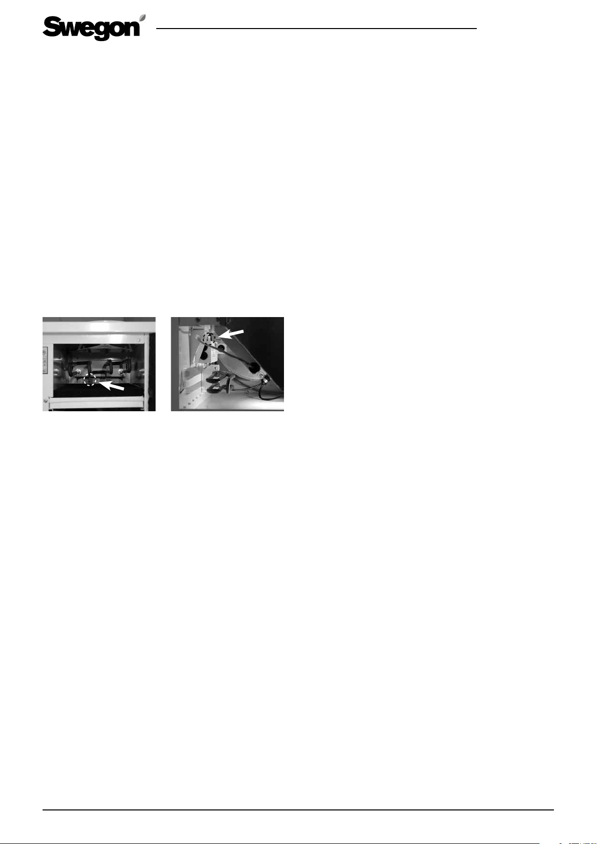
The overheating protection that requires manual resetting can be reset by pressing a button inside the ventilation unit. The location of the button inside the air
heaters is marked in the illustrations below. When you
press the reset button and feel it click, the overtemperature protection (thermal overload cut out) has then been
reset.
W100B.021014
Reset button for the overtemperature protection on
the preheating air heater
Reset button for the overtemperature protection on
the preheating air heater
(Only models with electric
air heater)
Econo model’s water-heated air heater
On the Econo models, there is a temperature sensor
that protects the water-heated air heater from freezing.
If the air heater’s temperature has dropped to a risky
level, the red signal lamp on the control panel will flash,
but the ventilation unit will operate normally.
If the air heater’s temperature drops further, the controller will stop the ventilation unit to prevent the air
heater from freezing. The anti-freeze protection alarm
is acknowledged from the ’Install. and service’ menu’s
’Alarm’ point.
The overheating protection of the fans
The fans have overheating protection. The fans stop
them if the temperature rises too high. They also stop
if a serious malfunction occurs in the ventilation unit.
The protective function resets itself automatically when
the temperature drops or the malfunction has been
remedied.
Swegon reserves the right to alter specifications. 5www.swegon.com/casa
Page 6
2. Installation
2
2.1 Ventilation unit installation site
The temperature in the installation space for the unit
should be more than +10 °C, and there should be a
drain in the installation space for draining off condensate. The ventilation unit can be installed in a machinery
room, laundry room, storeroom, etc. The ventilation unit
should not be secured to a wall that borders to a living
room or a bedroom.
During installation, arrange electric and control cables to
make them easily accessible.
The ventilation unit can be mounted either on the wall in
a wall mounting bracket or on the ceiling with a ceiling
mounting frame. The required mounting frame can be
purchased as an accessory (on the Dou model the wall
mounting bracket is included in the supply).
The unit should be mounted as near as possible to a wall
or ceiling. The space between the ventilation unit and the
wall/ceiling must be insulated to prevent the transmission
of sound through the wall behind the unit to the adjacent room.
W100B.021014
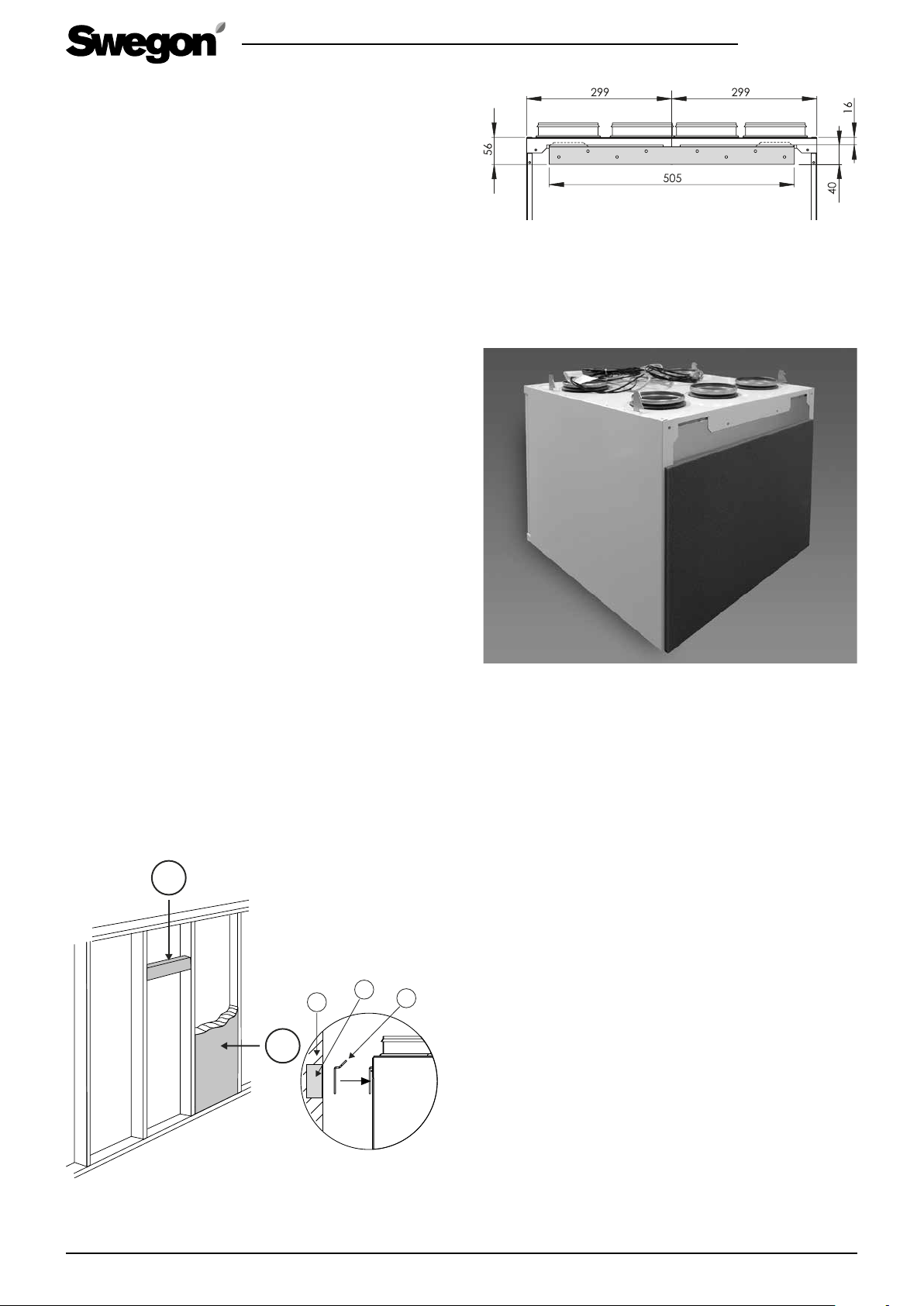
Wall mounting bracket’s dimensions
Screw the wall mounting firmly in horizontal position
onto the wall where a wall stud will support the weight
of the unit.
Connect the extract air from a Premium cooker hood, if
installed, via a duct to the extra duct connection spigot
on the top side of the ventilation unit, which on delivery
is plugged.
2.1.1 Wall mounting
Mount the ventilation unit on a wall by means of a wall
mounting bracket which is available as an accessory
(standard on the Duo models).
If the wall is composed of vertical studs and wall boards,
the wall must be reinforced with horizontal studs that
will support the weight of the unit. Swegon also recommends that the wall be insulated with mineral wool or
similar insulation for preventing sound from propagating to other rooms.
1
1
3
Fasten the insulation, supplied with the wall mounting
bracket, behind the ventilation unit.
Before you lift the ventilation unit into place, attach
the insulation supplied with the wall mounting bracket
onto the back side of the ventilation unit. Lift up the
ventilation unit onto the wall mounting bracket so that
the ears on the bracket engage in the corresponding
notches at the top on the backside of the unit. The ventilation unit’s inspection door and heat exchanger can
be removed to make it easier to lift the unit. The fans
can also be removed if necessary. See the ”Servicing”
Section.
1. Horizontal stud for the ventilation
unit’s mounting bracket
2. Acoustic insulation
6
2
1. Insulated wall
2. Horizontal stud
3. Wall mounting
bracket
Swegon reserves the right to alter specifications.www.swegon.com/casa
Page 7
W100B.021014
2.1.2 Ceiling mounting
The ventilation unit can also be mounted in a ceiling mounting frame (available as an accessory) on the
ceiling.
Fasten the ceiling mounting frame in ceiling anchor
pieces with four size M8 threaded rods. Adjust the
length of rods so that they will extend no more than
30 mm below the inner surface of the ceiling mounting
frame. If they extend further, they will interfere with the
upper section of the ventilation unit. Install at least three
threaded rods in the corners of the ceiling mounting
frame. To avoid a possible collision with the ducts, one
of the threaded rods can be located in the hole next to
the corner.
Screw in the M8 nuts onto the threaded rods to such a
height that the ceiling mounting frame will be horizontal when the top of the frame goes against the nuts. Fit
the ceiling mounting frame through the selected holes
towards the nuts of the threaded rods and lock the
frame into position with nuts from underneath. Adapt
the installation height so that the locking screws in the
ceiling mounting frame’s front section will extend sufficiently far below the ceiling.
Lift the ventilation unit up against the ceiling mounting
frame so that all four locking hooks engage into position. There are two catches on each locking hook. The
purpose of the upper one is to secure the ventilation
unit to facilitate connection to the ducts and the wiring
of the electric cables.
When the unit is in the correct position in relation to the
duct and the electric cables and water pipes, if required,
have been run into the ventilation unit, lift up the unit
to rest on the lower hooks. When the hooks are locked,
the spring-loaded screws of the front section of the
ceiling mounting frame extend outward. Finally, lock the
ventilation unit into position by tightening the screws.
Be careful not to press on the screws, because doing so will disengage the ventilation unit.
!
Important
!
If you improperly tighten the ceiling
mounting frame, this could turn the frame
and the ventilation unit will not have room
inside the frame.
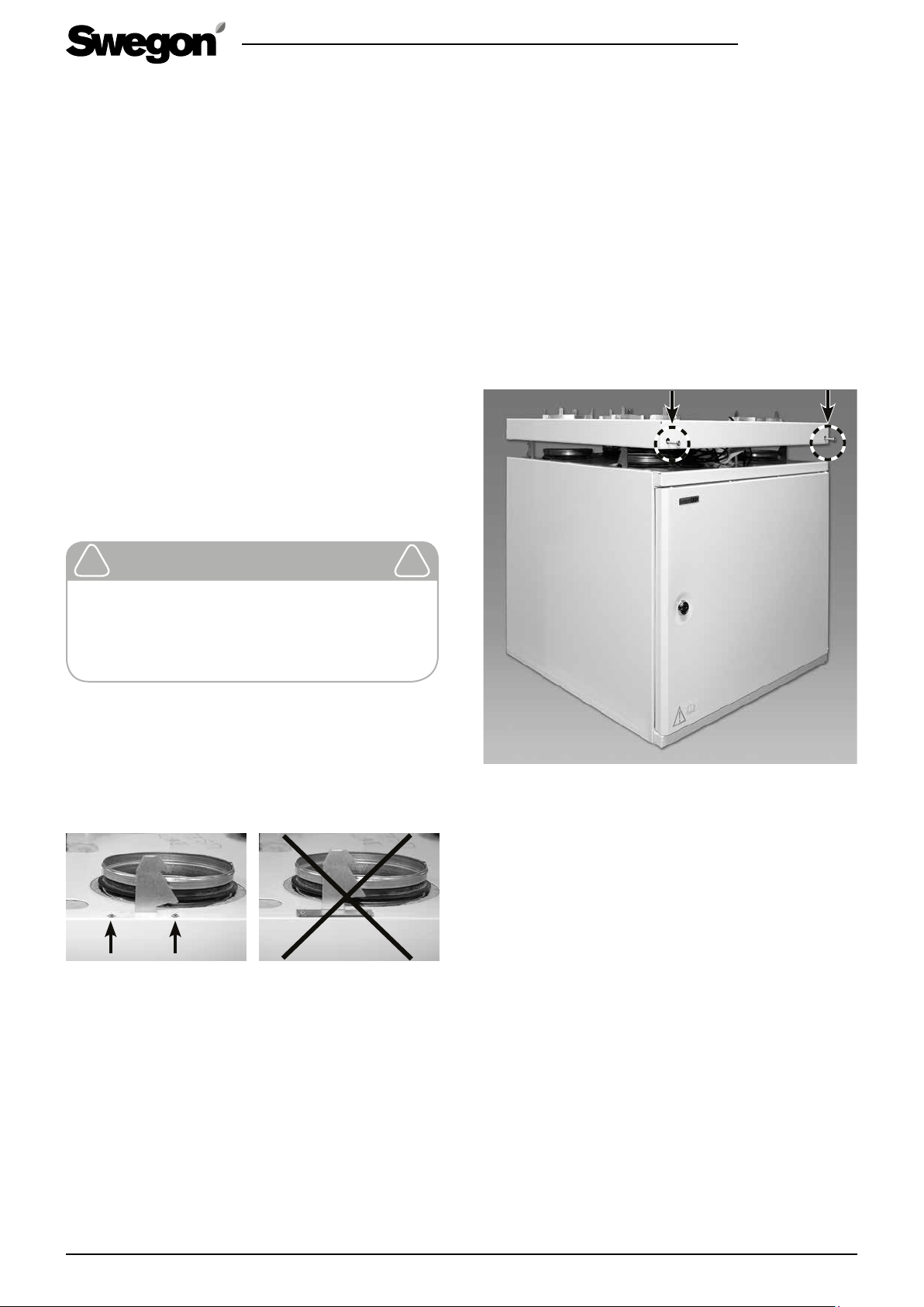
Run the mounting hooks through the assembly openings above the ventilation unit and secure them with
tension rivets. Position the hooks so that the sharp point
is facing the rear side of the ventilation unit.
The hooks must absolutely not be secured with rivets directly above the ventilation unit.
The points of the hooks face the rear part of the ventilation
unit and they are to be slipped into the unit’s notches before
you secure them with rivets.
Before you lift the ventilation unit into position, back
off the two screws at the front of the ceiling mounting
frame so much that the screw heads stick out approx. 2
cm. Also run the power supply and data cables, and on
the Econo model the water pipes, through the ceiling
mounting frame.
The ventilation unit’s inspection door and heat exchanger can be removed to make it easier to lift the
unit. The fans can also be removed if necessary. See the
”Servicing” Section.
Finally, lock the ventilation unit at its final location by
lightly tightening the locking screws.
The pipe connections of the Econo model should be arranged inside the ventilation unit. The connection work
will be facilitated if you temporarily remove the heat
exchanger and filter from the unit. Connect the inlet
flow pipes to the thermostat (3/8” female threads) and
the return pipe in the coupling with ∅ 15 mm on the
ball valve.
2.2 Condensate discharge
Connect the condensate discharge tube to the ventilation unit’s condensate discharge connection (3/8"
male threads). The condensate must be channelled to
a floor drain, the water trap of a sink or the equivalent
by means of a tube or a pipe having an inner diameter
of at least 12 mm. The tube must not be connected
directly to the sewer.
Vertically mount the water trap on the tube supplied
with the unit and fill it with water. The tube must not
have a second water trap or be run horizontally. The
damming height of the water trap should be at least
100 mm.
Swegon reserves the right to alter specifications. 7www.swegon.com/casa
Page 8
W100B.021014
2.3 Ducts
Install the air ducts, sound attenuators, supply air diffusers, air intake grilles and exhaust air ducts as shown in
the ventilation drawings. To prevent the propagation of
sound, do not install the ducts directly against structural
building elements.
Insulate the air ducts according to the ventilation plan in
order to reduce the losses of heat or cooling and to prevent water from condensing on surfaces. The applicable
fire resistance insulation requirements are also specified
in the ventilation plan. It is of greatest importance to
insulate cold ducts without gaps in the insulation,
so that moisture cannot condense.
!
Important
!
Check whether the ventilation unit has
been supplied in the right-hand or lefthand version to make certain that you are
connecting the air ducts to the correct duct
connection spigots on the unit. Check the
ventilation plans to make sure that the
duct connections are correctly installed.
See also the dimensional drawings in the
Section entitled: “Technical data”.
2.4 To connect the cooker hood
The cooker hood is usually connected to the ordinary
extract air duct. However the cooker hood can be
connected to the ventilation unit’s separate extract air
connection, in order to meet national regulations or for
achieving a more effective than normal extract airflow.
The duct between the cooker hood and the ventilation
unit must be installed in such a way that makes it possible to clean it.
On delivery, the connection for separate extract air is
blanked off.
If you connect the cooker hood to a separate extract air duct it is important to keep in mind that
the airflow will then bypass the heat exchanger
and this could cause an activation of the antifreeze protection function earlier than normal.
!
The bypass for a kitchen is intended for use
when the airflows from the cooker hood/
kitchen are boosted. The kitchen’s general
ventilation must take place via the extract
air duct. If the general ventilation takes
place continuously via the cooker hood, the
supply air and extract air flows through the
heat exchanger will be out of balance, and
this will lower the efficiency and impair
the ventilation unit’s anti-freeze protection
functions during the winter.
Important
!
2.5 To seal around duct penetration collars
We recommend the use of a mounting frame designed
for the ventilation unit (accessory) for sealing the vapour
barrier in the loft ceiling beams.
Cut up the openings with approx. 10 mm smaller
diameter than that of the ducts. Secure the mounting
frame in the ceiling with screws through the holes on
the sides. Tighten the plastic of the moisture barrier
between the mounting frame and the structural element of the building or fix it in position with tape tightly
against the mounting frame.
It is also important to the preserve the tightness of the
vapour barrier at the duct system’s other penetration
collars that run through the attic joists. A building element penetration seal (accessory) will facilitate this. This
item is available in sets of 5 pieces, for diameters: 100,
125 and 160 mm.
The thickness of the insulation and the nature of the
surface layer of the ventilation ducts vary depending on
insulation material, climate zone and national standards
in force. For this reason, Swegon does not offer any
recommendations. Most manufacturers of insulation
material offer calculation programs for the calculation of
sufficient and correct insulation.
In renovation projects, it is advisable to examine the
existing ducts to determine whether they are sufficiently
and correctly insulated. Insulating in the right way is
necessary for the ventilation unit to operate correctly..If
the ducts are uninsulated, even across a small area,
there is a high degree of risk of condensation and
indirect damage.
The supply air and extract air ducts should be fitted
with acoustic insulation along the stretch between the
ventilation unit’s duct outlet and the sound attenuator,
so that fan sound will not be propagated out into the
room.
In general, ventilation ducts should be insulated in the
following manner:
• Insulate outdoor air ducts run through warm spaces.
• Exhaust air ducts should always be insulated in accordance with national regulations. See separate
project planning instructions (e.g.e ”Fire resistance
requirements”).
• Insulate supply air ducts in cold spaces.
• Insulate extract air ducts in cold spaces.
• If the air inside the duct is colder than in the surroundings; the insulation should be protected by a
vapour barrier.
8
Swegon reserves the right to alter specifications.www.swegon.com/casa
Page 9
2.6 Electric and control cables
The electric and control cables are located on the upper
side of the ventilation unit.
A 1.5 m long cable with earthed plug-in contact is fitted
to the ventilation unit for measuring the voltage. The
mains plug serves as the ventilation unit’s main switch
and it should be connected to an electric socket at
an easily accessible spot. For power required, see the
Section entitled: “Technical data”.
Connect the ventilation unit to the Premium control
panel (accessory) via a modular cable. A 20 metre long
modular cable is included in the supply of the control
panel. Run the cable to the desired place where the
panel will be mounted. If the modular cable is run inside
some building element (e.g. a wall), run the cable in a ∅
20 mm conduit bearing in mind a possible later change
of cabling.
When installing the unit, make sure that you provide
adequate access to the connector of each cable (loose
ones as well), e.g. for servicing and adjusting the unit, if
and when the need arises.
In multi-storey buildings, a control panel can be used as
a so-called hand-held micro terminal in conjunction with
service and installation work.
The connection of possible accessories is described in
the wiring diagram in the Section entitled: ”Technical
data”. The cables for accessories are not included in the
supply.
!
If any further electrical wiring is required,
only a qualified electrician shall be allowed
to carry out this work.
The electric and control cables are located
on the upper side of the ventilation unit.
Make sure that the electric cable can
be connected to a wall outlet without
obstruction.
Important
!
W100B.021014
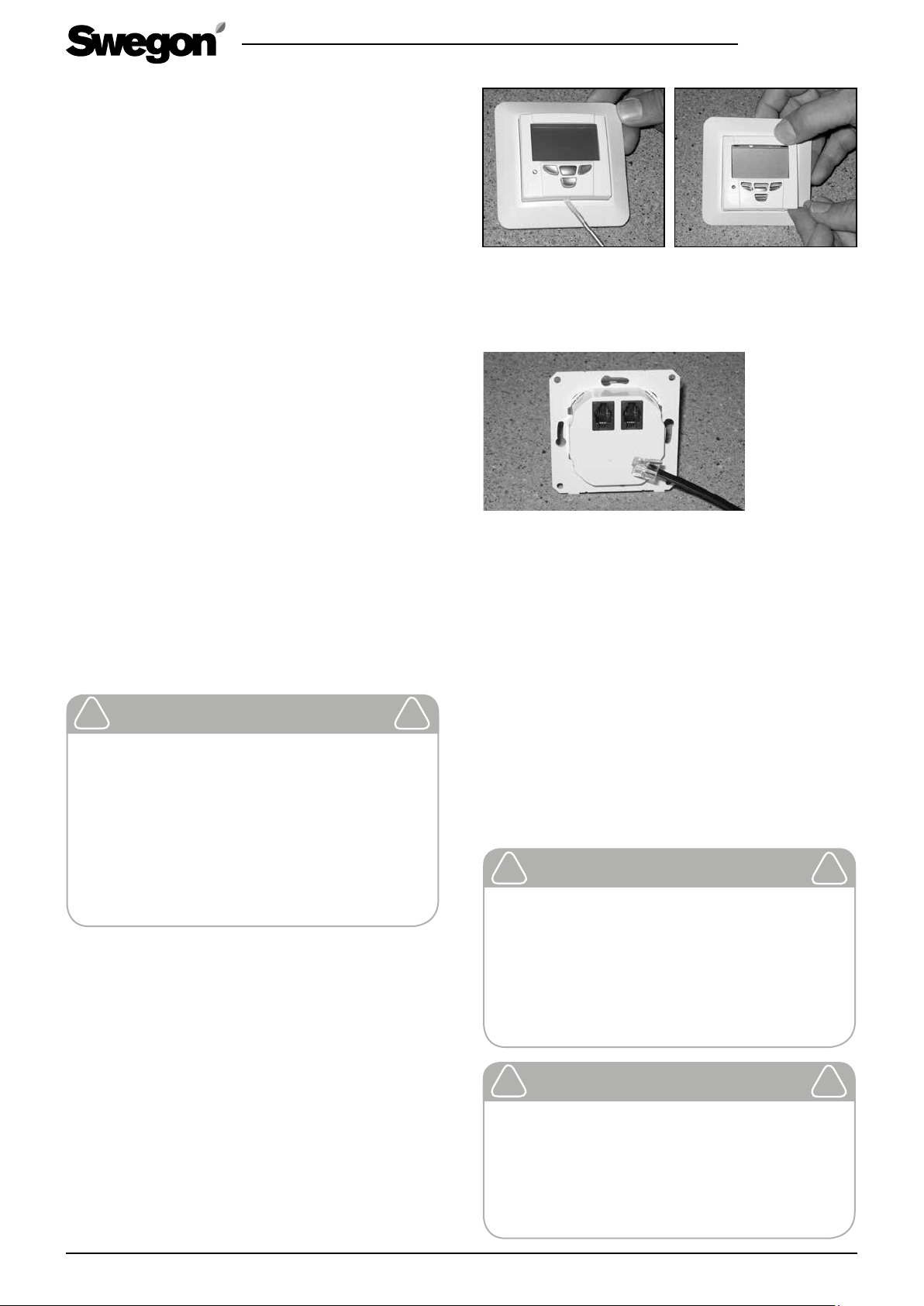
The front plate on the Premium control panel can be done
using a small screwdriver as shown in the figure. Put the front
plate back into place by first placing the upper edge of the
front plate in position and then pressing the plate firmly into
place.
To connect the modular cable. The extra plug terminal is used
for an extra control cable.
2.7 To connect water pipes in the Econo
model
The pipe connections of the Econo model should be arranged inside the ventilation unit. The connection work
will be facilitated if you temporarily remove the heat
exchanger and filter from the unit. Connect the inlet
flow pipe to the thermostat (3/8” female threads) and
the return pipe in the coupling with ∅ 15 mm on the
ball valve.
The Econo model requires a continuous circulation
of hot water during the heating season.
!
Check that the ventilation unit, filters and
ducts are clean and that there are no loose
objects in them before commissioning the
ventilation system.
The ventilation ducts should be cleaned
regularly and always when the home is
renovated.
Important
!
!
It is absolutely forbidden to operate the
ventilation system during the construction
period or if dust-raising work is carried out.
Before installing the unit, the ducts should
be blanked off with covers to prevent the
entry of impurities.
Swegon reserves the right to alter specifications. 9www.swegon.com/casa
Important
!
Page 10
3. Commissioning
3.1 To set the airflows
For estimated values for setting the airflows, use the
sizing curves in the Section entitled: ”Technical data”. A
qualified person should set the ventilation unit’s and the
ventilation equipment’s airflows using appropriate measurement equipment.
As an initial value for ventilation planning, you can use
the ventilation value 0.5 times the volume of the building per hour + 6 l/s supply air per person, when the unit
is operating in the Home mode. (Initial values can vary
in different countries.)
As a guideline in the Away fan mode, you can use 0.7 x air
volume in the Home mode. Scope for boosting should be
provided in accordance with regulations that apply in the
relevant country.
W100B.021014
3.2.4 Temperature
The supply air temperature is displayed in the main
menu if you select ”On”. (The models with electric
reheating.)
3.2.5 Measurement
Depending on the accessories connected, the following
values can be measured: carbon dioxide content (CO2),
temperature, pressure differential, the speed of the fans
and relative humidity (RH) as well as the light contact
(not on the R100).
3.2.6 Control functions
The carbon dioxide content (CO2), supervision (DDC)
weekly timer or RH control are selectable as control
means. With exception of the weekly timer, all the
control means require you to connect the accessory to
the system.
All the fan modes must be preset so that the ventilation unit will operate correctly. Fill in your entered
settings in the commissioning report.
3.2 Functions in the ’Install. and service’
menu in the Premium control panel.
From this menu, you can decide which functions you
want to be able to use from the main menu. From the
’Install. and service’ menu, you can also enter settings
that affect the ventilation system’s operation while you
commission or service the unit. Possible alarms and the
service reminder can also be acknowledged from this
menu.
3.2.1 To open the menu
To open the menu, enter code 1234.
3.2.2. Alarm
Sensor error
Alternative setting ”On” should be selected as the value
for the temperature sensors. If a possible sensor error
occurs, contact a service company. Sensor errors can
also be acknowledged from this menu.
Service reminder
After servicing, acknowledge the service reminder from
this menu with ”Service OK”. As factory setting, the service reminder is activated and the time interval for the
service reminder is sex months. The service reminder can
be deactivated and the time interval can be changed
from the Functions menu.
The freeze risk warning on the Econo models
If the air heater’s temperature drops to a risky level, the
“Freeze risk” alarm text will appear on the control panel
display. The air heater’s freeze risk warning can be acknowledged from the Freeze risk point. One prerequisite
for acknowledgement is that the temperature by sensor
T6 exceeds 16 °C.
3.2.3 Clock
The clock is displayed in the main menu if you select ”On”.
3.2.7 Fan settings
Situations
Select one of the five fan modes (1–5) for each operating
mode (Away, Home, Boost, Cool, Refresh and Heating).
The factory setting is Away 1, Home 3, Boost 5.
Speeds
For each fan mode(1–5), select fan speeds as percentage of the fan capacity (10–100 %). Enter the settings
separately for supply air and extract air.
!
Important
!
Set the fan speeds in accordance with national regulations when you commission
the ventilation system. The system should
be commissioned by a qualified person,
and the airflows must not be changed on
one’s own responsibility, since doing so
could disrupt the way the ventilation system operates.
3.2.8 Shutdown
The ventilation unit fans and the air heater, if fitted,
are switched off. The circuit card however is still being
supplied with voltage and the settings are retained in
the memory. The same function is also given in the main
menu.
3.2.9 Factory settings
All settings except the fan speeds are restored to the
factory settings.
3.2.10 Controllers
There is provision for using duct controls and valve motor if such accessories have been installed.
3.2.11 Functions
Negative pressure compensation
Put into operation if a cooker hood is connected to a
10
Swegon reserves the right to alter specifications.www.swegon.com/casa
Page 11

W100B.021014
separate power roof ventilator in the home, for instance, and a differential pressure switch for this function is located in the cooker hood’s extract air duct.
Service reminder value
Select ”On” if you want to use this function. The count
down period can be set to the length required (factory
technicians recommend 6 months).
Summer night cooling
If you set the value ”On”, the function will be displayed
in the main menu.
Heating
If you set the value ”On”, the function will be displayed
in the main menu.
Filter guard
Select the value ”On” if the filter guard accessory is
installed (not W100).
Fireplace function
Select ”On” if you want the function to be displayed in
the start menu.
Boost
Select ”On” if any of the boosting timer or presence
detector accessories are installed.
3.3 Application
Issues with reference to the usage of the ventilation
system are dealt with in the instructions for use supplied
with the unit.
3.2.12 Electric air heater
Air heater for preheating
Preheating is activated as the factory setting. Preheating
can also be deactivated, but if this is done, the ventilation unit’s protection against freezing must be ensured
in a different way.
When preheating is “In operation”, you can enter the
following:
• Required temperature limit value for the outdoor air
supplied to the ventilation unit (factory setting: -20
°C).
• Overtemperature – limit of the overtemperature
protection in the preheat chamber (factory setting:
50 °C).
When the anti-freeze protection is activated, the air
heater is always in operation.
The air heater for preheat can also be put in operation as a separate function while negative the pressure
compensation and/or fireplace function is operating.
The function can be limited based on the outdoor air
temperature, so that the air heater will not start unnecessarily. The factory setting for outdoor air temperature
is 0 °C.
Air heater for reheating (does not apply to the
Econo models)
As a factory setting, reheating is activated. It can also be
deactivated from this menu. When reheat is “In operation”, you can enter the following:
• Outdoor air temperature – you choose at which
outdoor air temperature the reheater is permitted to
start (factory setting: 15 °C).
• Overtemperature – limit of the overtemperature protection in the preheat chamber (factory setting: 50 °C).
Swegon reserves the right to alter specifications. 11www.swegon.com/casa
Page 12

4. Servicing
4.1 Service reminder
The service reminder is activated with preset time intervals and the ”Service reminder” text is displayed on the
Premium control panel. As a factory setting, the service
reminder is On. It can be taken out of operation under
the ”Service reminder” point in the ’Install. and service’
menu. As a normal value the service reminder is displayed at six month intervals, however you can change
the service reminder time.
After servicing, set the service reminder to zero from the
’Install. and service’ menu, ’Alarms’ point.
4.2 To open the ventilation unit
Before you begin any service work, isolate the power
supply voltage to the ventilation unit by pulling out its
electric plug from the wall socket. Wait a few minutes
before you open the inspection door of the ventilation
unit so that the fans have time to stop and possible air
heaters have time to cool down.
The inspection door can be opened by turning the lock
bolt with a screw driver for slotted screw heads.
4.3 Filters
The filters should be replaced twice a year; in the spring
and late in the autumn. The filters may need to be cleaned
or replaced more often in homes where there is considerable dust or if there are many particles in the outdoor air.
W100B.021014
wall of the ventilation unit.
Undo the locking devices and tilt the lower part of the
fan toward the rear wall until the fan disconnects from
the mounting bracket behind. Finally, turn the fan sideways and work it out of the ventilation unit. Be careful
not to damage the insulation on the electric cables.
If necessary, clean the fans with a soft brush. Be careful
not to dislocate the impeller balancing weights.
Reinstall the fans by inserting them and turning them
near their final positions. Tilt the lower part of the fans
toward the rear wall and move the discharge section
of the fan along the side wall toward the rear locking
device. Straighten the fan and push the locking bolt into
position though the cover in the partition wall and fasten
it at the intermediate wall with two screws. Connect
the plug-in contacts and install the heat exchanger and
extract air filter into position.
4.6 Other servicing
Clean the inner surfaces of the ventilation unit by
vacuum cleaning or with a damp cloth, if needed.
Check that the condensate discharge outlet is not
clogged and check its outflow by pouring water on
the bottom of the ventilation unit. The condensate
discharge connection is located on the rear of the unit
under the rotary heat exchanger.
The ventilation unit must not be operated without filters. Install only filters recommended by Swegon in the
ventilation unit. Check in the list of components that
you have selected correct filters.
4.4 Heat exchanger
You should check the condition of the heat exchanger
whenever you service the unit.
Withdraw the heat exchanger from the unit for inspection. Make sure that the passages through the heat
exchanger rotor are not clogged and clean them with a
brush, vacuum cleaner or running water as needed. If
you find it necessary to use detergent, choose one that
does not corrode aluminium.
Be careful not to damage the heat exchanger’s sensitive
foil structure and keep in mind that the passages should
be dry before you reinstall the heat exchanger in the
unit.
4.5 Fans
The fans can be removed from the ventilation unit for
cleaning or replacement.
Before you remove the fans, you must dismantle the
extract air filter and the heat exchanger from the ventilation unit. Then disconnect the plug-in contacts of the
fans (note the locking claws on the side of the contact.
Then unscrew the locking bolts located on the partition
12
Swegon reserves the right to alter specifications.www.swegon.com/casa
Page 13

Ventilation unit, right-hand model; on the model
in the left-hand version, the components are
mirror-inverted.
2
1
3
4
1. Extract air filter, G3
2. Supply air filter, PPI-20
3. Supply air filter, F7
4. Plate heat exchangers
W100B.021014
5
1. Extract air fan
2. Supply air fan
3. Condensate discharge connection
4. The fan’s locking device
5. The plug-in contact the fans
44
12
3
Swegon reserves the right to alter specifications. 13www.swegon.com/casa
Page 14

5. Alarms and troubleshooting
W100B.021014
5.1 Alarms from a Premium control panel
The alarms displayed on a Premium control panel are
described in the instructions for use.
5.2 Troubleshooting:
Possible malfunctions are indicated by alarm texts on
the Premium control panel. Inspect the components
related to the malfunction and remedy the malfunction.
5.2.1 The supply air is not sufficiently heated
Low temperature setting for supply air
Investigate and, if necessary, increase the temperature
from the Premium control panel or on the Econo model
with the thermostat inside the ventilation unit. At the
same time check that bypass for summertime operation
is not open.
Malfunction of the electric air heater (on the electric models only)
The air heater has overtemperature protection and one
overheating protection function. The alarm is initiated if
either of these is activated.
The overtemperature protection resets itself automatically when the temperature decreases. The overheating
protection must be reset by pressing a push button on
the air heater. If you hear a click when you press in the
button, this indicates that the overheating protection
has been reset.
Excessively high temperature may be due to too low an
air flow through the air heater. The cause can be that
a filter, outer wall grille or supply air device is clogged.
Replace and clean, if needed.
Tip: An insect net can be fitted inside the outer wall
grille. If the net has small mesh, dust and insects can
clog it. During certain conditions it is also liable to
freeze. Remove the net or replace it with a net with
larger mesh.
ventilation unit’s protective functions.
Priority 2: External supervision (DDC).
Priority 3: Normal operation from the control panel or
the cooker hood.
The control priorities are described in more detail in the
Section entitled: ”Control functions with accessories”.
!
Important
!
The ventilation unit must not be operated
without filters! Use only filters recommended by Swegon in the ventilation unit.
Find the correct filter in the Section entitled: ”Technical data”.
!
Important
!
Anti-freeze protection
During periods of cold weather, the heat
exchanger is liable to freeze if the extract
air is humid. A protective function then automatically reduces the speed of the supply
air fan. Under such conditions, variations in
the fan speed are therefore normal.
The LED on a Premium control panel flashes
green when the anti-freeze protection is
activated.
An excessively high temperature can also be due to the
supply air fan having stopped or that the temperature
sensor has been shaken loose from its position in the
suction opening of the fan.
If the bypass cover for summertime operation is not
completely closed, the air heater for reheating will not
switch on.
5.2.2 Badly isolated ventilation ducts
If the unit emits warm air but the supply air discharged
from the air diffuser feels cold, this may be due to
poorly insulated ventilation duct.
5.2.3 The ventilation unit does not obey commands
If two overlapping commands are issued, the unit obeys
the command with the highest priority, e.g. the antifreeze protection.
Priority 1: Commands from outer sensor or the
14
Reset button for the overtemperature protection on
the preheating air heater
Swegon reserves the right to alter specifications.www.swegon.com/casa
Reset button for the overtemperature protection on
the preheating air heater
(Only models with electric
air heater)
Page 15

6. List of components
11
2
2
34 9
99
6
10
5
7
8
1
W100B.021014
1. Temperature sensor
• 850 mm, without connector (T1/T8, outdoor air/exhaust air sensor): 604925
• 1,750 mm, with connector (T2, supply air sensor):
604920
• 1,100 mm, with connector (T3, extract air sensor):
604917
• 850 mm, without connector (T4, supply air sensor,
reheating): 604925
• 750 m, with connector (T7): excess temperature sensor, air heater for preheating) 604915
• 1,450 m, with connector (T6): excess temperature
sensor, air heater for preheating anti-freeze protection sensor for water-heated air heater): 604919
2. Fan package (ventilation unit, R Model)
3. Air reheater, reheat (models with electric air
4. Air heater, reheating (Econo, R model): 620220
-Supply air fan: PWEC175L
- Extract air fan: PEC119R
Fan package (ventilation unit, L Model)
- Supply air fan: PWEC175R
- Extract air fan: PEC119L
heater): 50269
Air heater, reheat (Econo, L model): 620221
5. Air heater, pre-heating: 60369
6. EC circuit card: 603010
7. Door contact: 60541
8. Condensate discharge tube: 502103
9. Set of filters: PW080FS
10. Heat exchanger: 61031
11. Door: DPW100RL
- Lock: 61957
Accessories, installation
• Set of filters: PW080FS
• Premium control panel: PSP143
• Ceiling mounting frame, PW100KA
• Wall mounting bracket: PW080SAT
• Mounting frame with vapour barrier: 10210WYP
Swegon reserves the right to alter specifications. 15www.swegon.com/casa
Page 16

7. Technical data
0
50
100
150
200
250
300
350
400
450
0102030405060708090100
100%
90%
70%
60%
50%
40%
110
80%
0
50
100
150
200
250
300
350
400
450
0102030405060708090100
110
100%
90%
80%
60%
50%
40%
70%
0
50
100
150
200
250
300
350
400
450
0102030405060708090100
110 120
60%
50%
40%
30%
70%
80%
90%
100%
0
25
50
75
100
125
150
175
200
225
0102030405060708090100
110120
250
275
30%
40%
50%
100%
90%
80%
70%
60%
0
25
50
75
100
125
150
175
200
225
0102030405060708090100
110120
250
275
30%
40%
50%
100%
90%
80%
70%
60%
0
50
100
150
200
250
300
350
400
450
0102030405060708090100
110 120
60%
50%
40%
30%
70%
80%
90%
100%
7.1 Fan Diagrams
W100B.021014
Supply airflow
Pressure differential, Pa
0
36 36072 108 144 180 216 252 288 324 396 0
Extract airflow
Airflow
Supply airflow, Econo
Available pressure, Pa
l/s
3
m
/h
36 36072 108 144 180 216 252 288 324 396
l/s
m3/h
Airflow
Extract airflow, Econo
Pressure differential, Pa
0
36 36072 108 144 180 216 252 288 324 396 432
Airflow
Power consumption
Total output, W
36 36072 108 144 180 216 252 288 324 396 432 0
0
16
Airflow
l/s
3
m
/h
Thick line = SFP 2.0 or lower.
l/s
3
/h
m
Available pressure, Pa
36 36072 108 144 180 216 252 288 324 396 432
0
Airflow
Power consumption, Econo
Total output, W
36 36072 108 144 180 216 252 288 324 396 432
Airflow
Swegon reserves the right to alter specifications.www.swegon.com/casa
l/s
m
l/s
m3/h
3
/h
Page 17

7.2 Outputs of the components
W100 EC W100 EC Econo
Connection 230 V, 50 Hz, 7.6 A 230 V, 50 Hz, 5.4 A
Fans 294 W 294 W
Air heater, preheating 1000 W 1000 W
Air heater, reheating 500 W -
Total output 1,800 W 1,300 W
Fuse protection 10 A 10 A
7.3 Acoustic data
Sound emitted to supply air duct
W100B.021014
Fan setting
%
40 61 57 53 45 44 38 31 20 50
50 67 62 62 52 48 43 37 26 56
60 70 66 61 54 52 45 42 32 58
70 73 69 65 58 55 51 48 39 62
80 75 71 68 61 57 54 50 42 65
90 78 73 71 64 59 56 53 45 67
100 79 75 75 67 60 58 55 47 70
63 Hz 125 Hz 250 Hz 500 Hz 1,000 Hz 2,000 Hz 4,000 Hz 8,000 Hz
Sound power level broken down into octave bands, L
, dB Total assessed
wokt
Sound emitted to extract air duct
Fan setting
%
40 49 49 41 35 28 20 - - 38
50 51 57 47 39 33 25 13 - 44
60 57 60 52 42 36 29 20 - 49
70 56 64 57 43 34 32 24 11 52
80 64 65 60 48 40 35 28 16 55
90 - 68 62 50 42 37 30 19 56
100 65 69 65 51 43 38 32 21 60
63 Hz 125 Hz 250 Hz 500 Hz 1,000 Hz 2,000 Hz 4,000 Hz 8,000 Hz
Sound power level broken down into octave bands, L
, dB Total assessed
wokt
sound power level
LWA, dB(A)
sound power level
LWA, dB(A)
Sound emitted to outdoor air duct
Fan setting
%
40 - - 37 30 27 17 - - 32
50 - 57 46 36 36 21 - - 44
60 59 62 51 42 36 30 17 - 49
70 59 64 55 45 40 32 22 - 51
80 66 67 58 49 41 37 28 15 54
90 - 68 61 52 44 39 32 20 57
100 59 71 64 55 47 42 36 24 60
63 Hz 125 Hz 250 Hz 500 Hz 1,000 Hz 2,000 Hz 4,000 Hz 8,000 Hz
Sound power level broken down into octave bands, L
Swegon reserves the right to alter specifications. 17www.swegon.com/casa
, dB Total assessed
wokt
sound power level
LWA, dB(A)
Page 18

Sound emitted to exhaust air duct
W100B.021014
Fan setting
%
40 59 57 47 43 42 37 28 17 47
50 65 63 54 48 47 40 36 24 53
60 70 68 58 52 50 45 41 30 57
70 68 71 62 56 53 49 45 35 61
80 78 74 66 60 56 52 49 40 64
90 79 77 70 62 57 55 51 42 67
100 79 77 71 64 58 56 52 44 68
63 Hz 125 Hz 250 Hz 500 Hz 1,000 Hz 2,000 Hz 4,000 Hz 8,000 Hz
Sound power level broken down into octave bands, L
, dB Total assessed
wokt
Sound emitted to duct for bypass from kitchen
Fan setting
%
40 - 42 42 37 33 32 19 - 40
50 58 54 50 43 39 34 27 12 46
60 56 59 55 46 43 38 33 20 51
70 59 62 59 49 45 42 37 25 54
80 - 65 63 49 48 45 41 30 57
90 - 67 66 53 50 48 43 32 60
100 66 69 67 54 50 48 44 34 61
63 Hz 125 Hz 250 Hz 500 Hz 1,000 Hz 2,000 Hz 4,000 Hz 8,000 Hz
Sound power level broken down into octave bands, L
, dB Total assessed
wokt
sound power level
LWA, dB(A)
sound power level
LWA, dB(A)
Sound emitted to the surroundings
Fan setting
%
40 42 44 37 25 27 19 - 10 33 29
50 44 46 43 32 25 22 12 - 37 33
60 43 50 45 35 27 26 18 11 39 35
70 64 53 46 34 29 29 22 11 43 39
80 65 55 49 35 31 32 25 11 45 41
90 66 58 51 39 33 34 28 13 47 43
100 62 60 53 40 37 36 29 14 48 44
Sound power level broken down into octave bands, L
63 Hz 125 Hz 250 Hz 500 Hz 1,000 Hz 2,000 Hz 4,000 Hz 8,000 Hz
*) Equivalent to a normally insulated room. If the values are changed to LWA, dB(A)-values, 4 units (dB) should be added to them.
, dB Total assessed
wokt
sound power
level
LW
dB(A)
A,
Sound pressure level
10 m² sound absorp -
tion
LP(10), dB(A)*
18
Swegon reserves the right to alter specifications.www.swegon.com/casa
Page 19

7.4 Sizing of the water-heated air heater
h
0 0,02 0,03 0,04 0,05 0,07 dm³/s
35
30
25
20
15
10
W100B.021014
Inlet flow water
°C
35
50
70
Airflow, l/s
Water flow
l/h
40
144
40 260 310 330
80 360 430 470
150 400 490 560
220 420 520 600
40 450 540 580
80 590 710 790
150 650 810 920
220 680 840 980
40 730 860 930
80 890 1070 1230
150 1000 113 0 1410
220 104 0 1280 1490
Air flow m
Capacity W
60
216
3
/h
80
288
7.5 Pressure loss in the air heater for reheating
Swegon CASA W100 Econo
Pressure loss in the air heater for reheat
Water-heated air
heater
Water-heated air heater +
thermostat
Pressure loss, kPa
5
0
0 50 100 150 200 250 dm³/
Water flow
Swegon reserves the right to alter specifications. 19www.swegon.com/casa
Page 20

7.6 Electrical wiring diagram
12
I
7.6.1 Ventilation unit
11
nput 230V 10A
S1
24
23
14
13
7
1000W
W100B.021014
6
T8
T4
T1
T7
RESET
ELECTRIC
EXHAUSTSUPPLY
TEMPINPUT
CO2I
NPUT%RHINPUT
SI
VA
KE
X21,
X21,2
X21,1
X11N
SI
X112
RU
SI
EC
AFTERHEAT
8
KE
VA
X11 -
X12 -
X21 -
X22,1
X22,2
X22,
X22 -
9
X12N
X122
EC
vastus
T6
T3
T2
2
3
4
5
1
1. Temperature sensor, see the Control diagram
2. Supply air fan plug contact
3. Supply air fan’s plug connector
4. Supply air fan’s DC contact
5. Extract air fan’s DC contact
6. Control panel (accessories)
7. Air heater, preheat, 1,000 W
7.6.2 Control functions with accessories
Priority 1: Commands from outer sensor or the ventilation unit’s protective functions.
Priority 2: External supervision (DDC).
Priority 3: Normal operation from the control panel or
the cooker hood.
14
13
S2
1S000192d
10
8. Triac controller
9. Air heater for reheat, 500 W
(only on the electrically heated models, not the
Econo)
10. Contact for bypass past the heat exchanger.
11. Door contact
To connect the modular cable.
Control priority 3
20
1. To cooker hood, control panel or Modbus gateway
2. To cooker hood, control panel or Modbus gateway
Swegon reserves the right to alter specifications.www.swegon.com/casa
Page 21

CO2 INPUT
TEMP INPUT
G+G0OUT1
OUT2MRelay
Relay
OUT4
G+
G0
OUT1
OUT2
M
Relay
Relay
OUT4
24V AC/DC
C
NC
NO
1
NC
2
3
NO
L
N
230V AC 50Hz
NC
NO
P
N
C
P
2
1
3
2
1
3
105TK
102TKC
117PK2
117HDL
117HDL
102LT
117KHH
105A1
2 x 0,5
2 x 0,5
2 x 0,5
2 x 0,5
2 x 0,5
3 x 0,5
4 x 0,5
5 x 0,5
2 x 1,5
230V AC 50Hz
2 x 1,5
2 x 0,5
2 x 0,5
M
24 VDC 2W (3,5VA)
M
24 VDC 2W (3,5VA)
1
2
3
4
5
6
7
8
9
10
Control priority 1
W100B.021014
*) Connect any of the functions, negative pressure compensation or boost to the BOOST/COMP contact. One
of the separate functions can also be wired to Input 4
on the DDC wiring terminal row. See DDC.
**) The use of the duct damper should be judged
on the basis of the specific case. The use of the duct
damper is recommended at least in the outdoor air
duct, especially on the Econo models.
1. Fireplace switch
2. Boost timer*
3. Humidity sensor
4. Timer
5. Sensor for negative pressure compensation*
6. CO
7. CO
8. Presence detector
sensor with relay
2
sensor
2
9. Damper actuator for duct damper – A outdoor
air duct**
10. Damper actuator for duct damper – B exhaust
air duct**
Swegon reserves the right to alter specifications. 21www.swegon.com/casa
Page 22

W100B.021014
Supervision (DDC)
Control priority 2
• The functions of wiring terminals 2-5 can be activat-
ed/deactivated from the control panel service menu.
• The status outputs (terminals 6 and 7) can always be
used
8: 0 V (GND)
7: The supply air temperature actual value: 0-10 V DC
(corresponds to 10–30 °C)
6: Fan speed actual value: 0-10 V DC
5: The supply air temperature control, 0-10 VDC
(corresponds to 10–30 °C) (Not on the Econo)
4: 0–10 VDC fan speed control*
3: Alarms – signal from the ventilation unit
(earthed contact)
2: Emergency stop (if contact between terminals 1-2 is
broken, the ventilation unit will stop).
1: 0 V (GND)
*) Voltages for fan speed control
Separate function via DDC terminal row
(e.g. Home/Away switch)
The following changes should be made in the functional
parameters of the ventilation unit using the Premium
control panel:
• Change the fan speed in the Boost mode from speed
5 to speed 4 from the menu::Install. and service/
fan speeds/Situations.
• Set the separate supply and extract airflow functions
to speed5 from the menu: Installation and service/
Fan speeds/Speeds.
• Activate control of the fan speed via DDC from the
menu: Install. and service/Control/DDC/Fan con-
trol system.
Speed 1 = 1–2.9 VDC
Speed 2 = 3–4.9 VDC
Speed 3 = 5–6.9 VDC
Speed 4 = 7–8.9 VDC
Speed 5 = 9–max. 24 V DC
Control priority 3
0-0.9 V DC
Alarm output
max 40V, 500mA
Close = alarm
Open = no alarm
24VDC
max 500mA
Delivery demarcation
DDC CONTROL
1 2 3 4 5 6 7 8
1 2 3 24V P2 P1 0
A2
A1
Contact broken = Activation of
the separate
function
Open contact = Normal use
of the separate
function
22
Swegon reserves the right to alter specifications.www.swegon.com/casa
Page 23

7.7 Control diagram
1
2
3
4
5
6
7
8
9
10
11
12
13
7.7.1 W100 EC
W100B.021014
1: Group electrical distribution box | 2: Electrical equipment cubicle | 3: Exhaust air | 4: Outdoor air | 5: Power supply: 230 V, 10 A
with plug-in connection | 6: The damming height of the water trap, 100 mm | 7: Supply demarcation of the ventilation unit | 8:
Extraction from cooker hood, bypasses the heat exchanger | 9: General ventilation | 10: Supply air | 11: Modular cables with RJ9
connectors | 12: Control panel | 13: Cooker hood
SYMBOL DESIGNATION EXPLANATION
T1 TEMPERATURE SENSOR Temperature sensor, outdoor air
T2 TEMPERATURE SENSOR Temperature sensor, supply air
T3 TEMPERATURE SENSOR Temperature sensor, extract air
T4 TEMPERATURE SENSOR Temperature sensor, supply air, reheating
T6 TEMPERATURE SENSOR Excess temperature sensor for the reheating air heater
T7 TEMPERATURE SENSOR Excess temperature sensor for the preheating air heater
T8 TEMPERATURE SENSOR Temperature sensor, exhaust air, anti-freeze protection
TZ01 OVERHEATING PROTECTION Overheating protection with manual reset
TZ02 OVERHEATING PROTECTION Overheating protection with manual reset
HSx.1 MANUAL TIMER SWITCH Control of the fans and the cooker hood damper
DESCRIPTION OF THE FUNCTIONS
CONTROL FUNCTIONS:
The ventilation unit can be operated from a separate Premium control panel or a Premium cooker hood.
When the ventilation unit is controlled from the cooker hood in the Home/Away/Boost modes and for local extraction, the time can be set to 30, 60
or 120 minutes.
The supply air temperature is regulated from the Premium control panel. When necessary, the reheating function can also be switched off from the
control panel.
Summer operation: In the summer, the supply air is steered past the heat exchanger when the controller opens the bypass cover.
– Overheating protection for the reheating air heater: The air heater for reheating is equipped with a manually re-settable TZ01 automatic thermo-
stat (preset limit value: 90 °C) as protection against overheating.
– Overheating protection for the preheating air heater: The air heater is equipped with a manually re-settable type TZ01 automatic thermostat
(preset limit value: 90 °C)
as protection against overheating.
– The fans have automatic overtemperature protective devices.
IF THE SAFETY EQUIPMENT TRIPS:
– If an overheating protection with manual reset trips, it can be reset by pressing a reset button above the air heater.
– The automatic overheating protection of the fan will reset itself when the temperature has dropped below the setpoint.
Swegon reserves the right to alter specifications. 23www.swegon.com/casa
Page 24

7.7.2 W100 EC Econo
W100B.021014
1: Group electrical distribution box | 2: Electrical equipment cubicle | 3: Exhaust air | 4: Outdoor air | 5: Power supply: 230 V, 10 A
with plug-in connection | 6: The damming height of the water trap, 100 mm | 7: Supply demarcation of the ventilation unit | 8:
Extraction from cooker hood, bypasses the heat exchanger | 9: General ventilation | 10: Supply air | 11: Modular cables with RJ9
connectors | 12: Control panel | 13: Cooker hood | 14: E.g. floor heating circuits
SYMBOL DESIGNATION EXPLANATION
TC1 TEMPERATURE CONTROLS Temperature control for the reheating air heater
T1 TEMPERATURE SENSOR Temperature sensor, outdoor air
T2 TEMPERATURE SENSOR Temperature sensor, supply air
T3 TEMPERATURE SENSOR Temperature sensor, extract air
T4 TEMPERATURE SENSOR Temperature sensor, supply air, reheating
T6 TEMPERATURE SENSOR The anti-freeze protection sensor of the water-heated air heater
T7 TEMPERATURE SENSOR Excess temperature sensor for the preheating air heater
T8 TEMPERATURE SENSOR Temperature sensor, exhaust air, anti-freeze protection
TZ02 OVERHEATING PROTECTION Overheating protection with manual reset
HSx.1 MANUAL TIMER SWITCH Control of the fans and the cooker hood damper
DESCRIPTION OF THE FUNCTIONS
CONTROL FUNCTIONS:
The ventilation unit can be operated from a separate Premium control panel or a Premium cooker hood.
When the ventilation unit is controlled from the cooker hood in the Home/Away/Boost modes and for local extraction, the time can be set to 30, 60
or 120 minutes.
The supply air temperature can be set with a mechanical thermostat inside the ventilation unit. Whenever necessary, the reheating function can be
switched off by setting the thermostat to the zero setting.
Summer operation: In the summer, the supply air is steered past the heat exchanger when the controller opens the bypass cover.
– Overheating protection for the preheating air heater: The air heater is equipped with a manually re-settable type TZ01 automatic thermostat
(preset limit value: 90 °C)
as protection against overheating.
– The water-heated heat exchanger is equipped with a type T6 anti-freeze protection device.
– The fans have automatic overheating protections.
IF THE SAFETY EQUIPMENT TRIPS:
– If an overheating protection with manual reset trips, it can be reset by pressing a reset button above the air heater.
– The automatic overheating protection of the fan will reset itself when the temperature has dropped below the setpoint.
– Frost damage protection a water-heated air heater: Thermostat TC1 will open the heating system’s valve completely if the air temperature is lower
than 12 °C by the thermostat sensor. If the return water temperature drops 10 °C below the temperature by the type T6 sensor, the controller will
switch off the supply air fan. The fan will starts again when the supply air temperature has risen above the value preset on the thermostat.
24
Swegon reserves the right to alter specifications.www.swegon.com/casa
Page 25

7.8 Dimensions
W100B.021014
Swegon CASA W100 R
7
377
597
0
120
298
0
130
451
2
432
3
476
597
70
493
523
599
Swegon CASA W100 L
154
3
8
1 2 3 4 5
Supply air
∅ 160
6. Radiator connections ∅ 15 mm
7. Condensate drain connection
8. Cable gland for electric and control cables
2
6
Extract air
∅ 160
Duct connections
Outdoor air
∅ 160
220
Exhaust air
∅ 160
7
Separate
extract air
∅ 125
599
6
8
7.9 Weights
Ventilation unit: 47 kg.
7.10 Ventilation unit codes
Project models
(without wall mounting bracket and control panel)
• W100 Premium
R (right-hand version) PW100SR
L (left-hand version) PW100SL
• W100 Premium Econo
R (right-hand version) PW100ER
L (left-hand version) PW100EL
Duo models
(with wall mounting bracket and control panel)
• W100 Premium Duo
R (right-hand version) PW100SRN
L (left-hand version) PW100SLN
• W100 Premium Duo Econo
R (right-hand version) PW100ERN
L (left-hand version) PW100ELN
7.11 Accessories for installation
• Mounting frame with vapour barrier (R/L): 10280YP
• Ceiling mounting frame (R/L): PW100KA
• Wall mounting bracket: PW080SAT
• Set of replacement filters: PW080FS
1 pc. G3
1 pc. F7
1 pc. PPI-20
• Building element penetration seal for duct, 5 pc. per
package
∅ 100 mm: 102LT10
∅ 125 mm: 102LT12
∅ 160 mm: 102LT16
Swegon reserves the right to alter specifications. 25www.swegon.com/casa
Page 26

W100B.021014
8. Commissioning form
Function Factory setting Setting value
Temperature, supply air (not on the Econo models) 17 °C
Base display 1
Clock On
Temperature(not on the Econo models) On
Fan speeds (situations).
Away 1
Home 3
Boost 5
Cool off 4
Refresh 4
Heating 3
Fan speeds
Speed 1, supply air fan 50 %
Speed 1, extract air fan 50 %
Speed 2, supply air fan 60 %
Speed 2, extract air fan 60 %
Speed 3, supply air fan 70 %
Speed 3, extract air fan 70 %
Speed 4, supply air fan 85 %
Speed 4, extract air fan 85 %
Speed 5, supply air fan 100 %
Speed 5, extract air fan 100 %
Negative pressure compensation Off
Service reminder In operation option
Interval 6 months
Heat(not on the Econo models) In operation option
Temp. limitation 50 °C
Control Supply air controlled
Filter guard not W100) On
Fireplace switch function (with fireplace switch) Off
Boost (with boost timer or presence detector) In operation option
Outdoor temperature limit, for activation of air heater 15 °C
26
Swegon reserves the right to alter specifications.www.swegon.com/casa
Page 27

W100B.021014
Airflows Project planning values Setting value
Supply air, total l/s m3/h l/s m3/h
Away
Home
Boost
3
Extract air, total l/s m
Away
Home
Boost
N.B.! All the fan modes should be preset.
Other comments
/h l/s m3/h
Data for the ventilation unit
Write down the data on the ventilation unit identification plate for reference when the need arises to contact a service
company.
Preset by: Date:
!
It is essential for correct ventilation unit
operation that the airflow rates are preset
according to the ventilation plan.
Swegon reserves the right to alter specifications. 27www.swegon.com/casa
Important
!
!
Remember to explain the use of the item of
optional equipment and how to service it
to the user/caretaker!
Important
!
Page 28

W100B.021014
Warranty Conditions
GUARANTOR
Swegon ILTO Oy
Asessorinkatu 10, FI-20780 St. KARINS, Finland.
WARRANTY PERIOD
The product has a two (2) year warranty as from the date of purchase.
SCOPE OF THE WARRANTY
The warranty covers defects that have arisen during the warranty period, which have been reported to the manufacturer, or been declared by the warrantor or a representative of the warrantor, and which refers to design, manufacture or material defects as well as
consequential defects that have arisen on the product itself. The above mentioned defects are to be cleared by putting the product
in working order.
GENERAL WARRANTY LIMITATIONS
The warrantor’s warranty liability is limited in accordance with these warranty conditions and the warranty does not cover damages
to property or personal injury. The warrantor is not bound to comply with verbal promises in addition to this warranty agreement.
LIMITATIONS ON WARRANTY LIABILITY
This warranty is granted on condition that the product is used in a normal way or under comparable circumstances for the intended
purpose, and that the instructions for use have been observed.
The warranty does not cover faults that have been caused by the following:
- Transport of the product.
- Careless use or overloading the product.
- Failure to follow the instructions dealing with installation, operation, maintenance and care.
- Incorrect installation of the product or incorrect location at the place where it is used.
- Circumstances which are not the fault of the warrantor, such as excessive variations in voltage, damage by lightning and fire or
other accidents.
- Repairs, maintenance or design modifications that have been done by unauthorized parties.
- Neither does the warranty cover insignificant defects from an operational standpoint such as scratches on surfaces.
- Parts, which through handling or normal wear are exposed to a greater than normal risk of failure, such as lamps, glass, porcelain,
paper and plastic parts as well as fuses are not covered by the guarantee.
- The guarantee does not cover settings, information about usage, maintenance, service or cleaning which is normally described in
the instructions for use or the work required to rectify faults caused by the user neglecting to observe the warning or installation
instructions, or investigation of such.
CHARGES DURING THE WARRANTY PERIOD
The authorized service partner will not charge the client for repairs, replaced parts, repair work, transport or travelling expenses
necessary for carrying out the repair work that are within the scope of the warranty.
This however assumes the following:
- The defective parts are handed over to the authorized service partner.
- that the repair begins and the work is carried out during normal working hours. The authorized service partner has the right to
charge the client for extra costs for urgent repairs, or repairs carried out outside of normal working hours. However if the defects
may cause a health risk or substantial economic losses, the defects will be repaired immediately without extra charge.
- A service vehicle or public means of transportation that follows a timetable (boats, airplanes or snow vehicles are not considered
public means of transportation) can be used in conjunction with the repair of the product or replacement of defective parts.
- The costs for dismantling and installation of equipment, which is securely mounted to the place where it is used, cannot be consid-
ered as being abnormal.
REMEDIAL MEASURES WHEN A FAULT HAS BEEN DISCOVERED
If a defect is discovered during the warranty period, the client must without delay report the defect to the dealer or to an authorized
service partner (www.swegon.com/casa). Specify which product has a defect (product model, type designation on the warranty card
or on the product identification plate, serial number); describe the type of defect as accurately as possible, and the circumstances
under which the defect has arisen. If there is risk that the fault may have consequential impact on the environment, the ventilation
unit must be switched off immediately.
A prerequisite for valid warranty liability is that the manufacturer or a representative of the manufacturer is given opportunity to
inspect the defects reported in the warranty claim before the repair work begins. A prerequisite for repair under warranty is also that
the client, in a satisfactory manner, can prove that the warranty is valid (= written receipt of purchase). After the warranty period has
expired, warranty claims, which have not been submitted in writing prior to the expiration date of the warranty period, are not valid.
Swegon ILTO Oy, Asessorinkatu 10, FIN-20780 St. Karins, Finland, www.swegon.com/casa, unit.warranty@swegon.fi
28
Swegon reserves the right to alter specifications.www.swegon.com/casa
Page 29

W100B.021014
EC Declaration of Conformity
We at:
Swegon ILTO Oy
Asessorinkatu 10
20780 St. Karins
FINLAND
hereby affirm that
the Swegon CASA W100B ventilation units
comply with the following EC Directives:
The machinery Directive (2006/42/EC)
Low Voltage Directive (2006/95/EC)
The EMC Directive (2004/108/EC)
and that the following harmonised standards have been applied:
EN 60335-1:2002 +A1:2004 +A11:2004 +A12:2006 +A13:2008 +A14:2010 +A15:2011 +A2:2006
EN 60204-1:2006 +A1:2009
EN 60034-5:2001 +A1:2007
EN 55014-1:2006 +A1:2009 +A2:2013
EN 55014-2:1997 +A1:2001 +A2:2008
EN 61000-3-2:2006 +A1:2009 +A2:2009
EN 61000-3-3:2008
Person authorised to compile the technical documentation:
Name: Mikko Jokinen
Address: Asessorinkatu 10, 20780 St. Karins, Finland
E-mail: mikko.jokinen@ilto.fi
Date: St. Karins, 7.5.2013
Signature:
Peter Stenström
CEO
Swegon ILTO Oy
N.B.! The document’s original language is English.
Swegon reserves the right to alter specifications. 29www.swegon.com/casa
Page 30

W100B.021014
30
Swegon reserves the right to alter specifications.www.swegon.com/casa
Page 31

W100B.021014
Swegon reserves the right to alter specifications. 31www.swegon.com/casa
Page 32

www.swegon.com/casa
 Loading...