

Swegon CASA series Installation, Operation And Maintenance Instructions
Installation, operation and maintenance instructions
for design engineers, installation engineers and service personnel
PTH_a_EN–m
Swegon CASA® Regulation for
constant duct pressure
Important information
Only qualified personnel
Only qualified personnel should carry
out installation, configuration and
commissioning.
Important details to consider
during installation
The installation point affects the
measurement result. The sensor must be
installed at a point where the airflow is as
even as possible.
Commissioning
The pressure sensor may not be installed
until all work that produces large quantities
of sanding dust or other impurities has been
completed.
Make sure that the ducts are clean and that
there are no loose objects in them before
commissioning.
NOTE! The manual’s original language is Finnish.
!
Included in the delivery:
• Pressure sensor
• Measuring tube
• Measurement tapping
• Instructions
2
PTH.191017
Swegon reserves the right to make changes.www.swegonhomesolutions.com
3.1. Installation of the sensor in the duct
system
Install the pressure sensor close to the measurement
point. When measuring the (positive) pressure on the
supply air duct, connect the measuring tube to the tapping on the pressure sensor (+). When measuring the
(negative) pressure on the extract air duct, connect the
measuring tube to the tapping on the pressure sensor (-).
3.2. Electric and control cables
Connect the 3-wire cable from the pressure sensor to
the ventilation unit’s I/O connection according to the
wiring diagram.
NOTE! Make sure that the strain relief is arranged
for the connections according to the electrical
safety directives.
3. Installation
The constant duct pressure function on the Smart ventilation unit attempts to regulate the fan speeds to maintain the duct pressure at the set value. Individual setting
values for the duct pressure should be determined for
each operating mode (away, home, boost). The operating mode can be switched as normal when the constant
duct pressure function is used.
1. General Description
2. Planning
Select the position of the measurement tapping point
in the duct with care, so that as far as possible it represents the pressure in the entire duct system. For example, a suitable location is close to the ventilation unit,
yet so the airflow is still uniform in the measurement
point. The measurement is based on the pressure difference, and therefore the other measurement sensor must
be positioned so it represents the air that surrounds the
duct, and where the air is stable.
Important
Only a qualified electrician may make the
electrical connections.
!
!
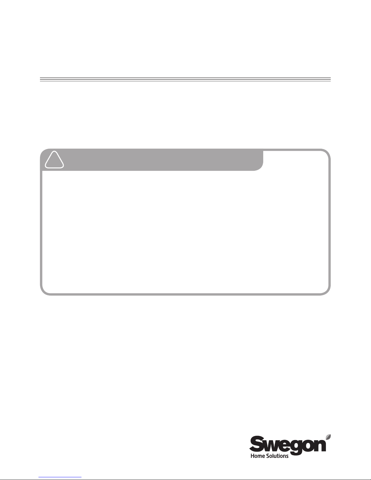
4. Commissioning
The commissioning of regulation for constant air pressure is performed with a Smart control panel. Main
menu/Settings/(1234)/IO controls
IO controls
IO 1
IO 2
IO 3 (ext.)
IO 4 (ext.)
Pa Extract - AI
Away - DI
Emg.Stop_NO - DI
Pa Supply - AI
IO 5 (ext.)
DDC control - AI
Select connections that correspond to the IO-points Pa
Supply - AI / Pa Extract - AI. Example: “Pa Supply - AI”
as a function for IO 1 and “Pa Extract - AI” as a function
for IO 2.
The pressure setting values and airflows must be adjusted for all operating modes (Home, Away, Boost), so that
the ventilation unit functions in all conditions.
NOTE! The constant duct pressure function is not
activated until you have set the values for all operating modes.
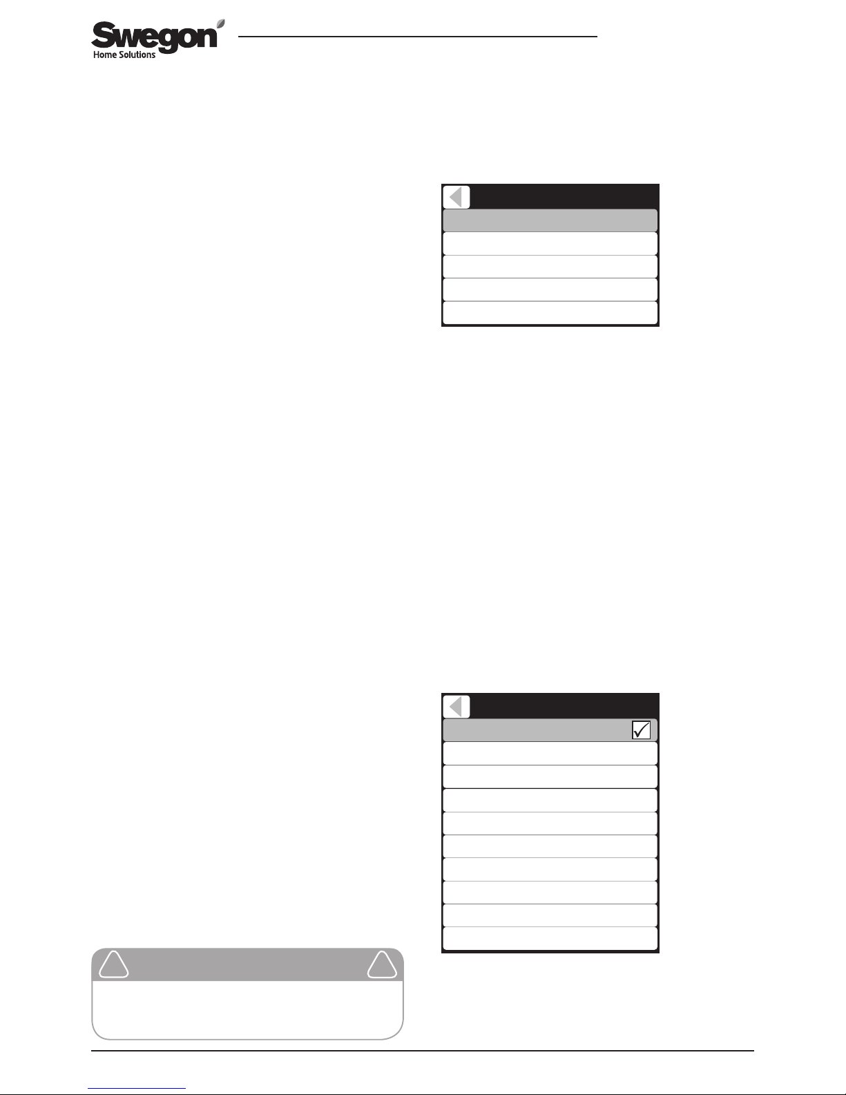
The control type for the ventilation unit is selected and
the airflow is set from the menu Main menu/settings/
(1234)/Airflow adjustments.
Airflow adjustments
Commissioning mode
Home (exhaust)
Away (supply)
Away (exhaust)
Boost (supply)
Boost (exhaust)
Travelling (supply)
Max Smart boost (supply)
50 Pa
35 Pa
38 Pa
90 Pa
92 Pa
35 Pa
82 Pa
Control type Pa
Home (supply) 48 Pa
Select “Pa” as the control type of both ducts that are to
be regulated for a constant duct pressure. If the control
type is set to “Pa Supply” or “Pa Extract”, the selected
duct is solely regulated for constant duct pressure and
5. Settings
 Loading...