

Swegon CASA R3 Smart, CASA R2 Smart Installation, Commissioning And Maintenance Instructions
Page 1
R3_g_EN-t
Installation, commissioning and maintenance instructions
CASA® R3 Smart
Page 2

2
R2.060219
All rights to changes reserved.www.swegon.com
NOTE! The manual’s original language is
English.
Contents
Technical Guide
for design engineers, installation engineers and service personnel
The section 1 describes the high lights of the unit.
All information for mechanical installation is found from section 2.
Instructions for basic commissioning is found from section 3.
Units external connections to the systems or devices like Modbus, DI, DO, AI, etc. is found from section 4.
Units functions description and usage is found from section 5.
Units periodically maintenance and service is described in section 6.
If a malfunction or alarm occurs the instructions are found from section 7.
All technical data is found from section 8.
Important information ............................................. 3
1. General Description .............................................. 4
1.1 Enclosure .........................................................................4
1.2 Fans ................................................................................. 4
1.3 Demand ventilation control ..............................................5
1.4 Filter ................................................................................5
1.5 Heat exchanger ................................................................5
1.6 Temperature ....................................................................5
1.7 External connections ........................................................ 5
1.8 Protective functions .........................................................5
2. Installation ............................................................. 6
2.1 Ventilation unit’s installation site ......................................6
2.1.1 Wall mounting ........................................................6
2.1.2 Ceiling mounting ....................................................6
2.1.3 Installation of the cooker hood directly on the
ventilation unit ................................................................. 7
2.1.4 Installation of the cooker hood separately from the
ventilation unit ................................................................. 7
2.2 Condensate discharge ......................................................8
2.3 Ducts ............................................................................... 8
2.3.1 Commissioning the bypass for the kitchen...............9
2.4 Electric and control cables ..............................................10
2.5 Installation of the Smart control panel ............................10
2.6 Accessories ....................................................................11
2.6.1 Smart sensor package ...........................................11
3. Basic commissioning ........................................... 12
3.1 Air flows ........................................................................ 12
3.1.1 Setting the basic airflows.......................................12
3.1.2 Travelling ...............................................................12
3.1.3 Maximum automatic boost....................................12
3.1.4 General notifications ............................................. 12
3.2 Cooker hood function ....................................................13
4. Units external connections................................. 14
4.1 Modbus ......................................................................... 14
4.2 Switch inputs (DI) ........................................................... 15
4.3 Voltage inputs (AI) .........................................................15
4.4 Relay outputs ................................................................. 16
4.5 Voltage outputs (AO) .....................................................16
4.6 Smart Access .................................................................16
5. Functions and use ............................................... 18
5.1 Functions ....................................................................... 18
5.1.1 Shortcuts ..............................................................18
5.1.2 Summer night cooling ........................................... 18
5.1.3 Cooker hood function ........................................... 19
5.1.4 Central vacuum function ....................................... 19
5.1.5 Fireplace function ..................................................19
5.1.6 Automatic Home/Away/Boost function ..................19
5.1.7 Automatic humidity control ...................................20
5.1.8 Automatic air quality control .................................20
5.1.9 Weekly program ....................................................20
5.2 Supply air temperature control .......................................21
5.2.1 Temperature control settings ................................21
5.2.2 Temperature measurement ....................................21
5.2.3 External heating and cooling units ......................... 21
5.3 Anti-frost protection ......................................................22
5.4 Restoring factory settings ............................................... 22
5.6 Changing settings password ..........................................22
5.7 Use ................................................................................ 22
6. Service .................................................................. 23
6.1 Service reminder ............................................................23
6.2 To open the ventilation unit ...........................................23
6.3 Filters ............................................................................. 23
6.4 Heat exchanger ..............................................................23
6.5 Fans ............................................................................... 24
6.6 Other servicing ............................................................... 24
6.7 Diagnostics ....................................................................24
7. Alarms and Troubleshooting .............................. 26
7.1 Alarm indication, cooker hood ....................................... 26
7.2 Alarm indication, control panel ......................................26
7.3 Troubleshooting ............................................................. 26
7.4 Alarm descriptions .........................................................27
8. Technical data ...................................................... 28
8.1 List of components ........................................................28
8.2 Air flows (EN 13141-4) ...................................................29
8.3 Connection outputs ....................................................... 29
8.4 Acoustic data ................................................................. 30
8.5 Electrical wiring diagram ................................................ 31
8.5.1 Ventilation unit .....................................................31
8.5.2 R3, CASA Jazz cooker hood and control panel ......31
8.6 Control diagram ............................................................32
8.7 Measurements ...............................................................33
8.8 Weights .........................................................................34
8.9 Ventilation unit’s codes ..................................................34
8.10 Accessories for installation ...........................................34
Commissioning form ............................................... 35
Page 3
R2.060219
All rights to changes reserved.
3
www.swegon.com
Important information
Installation and commissioning
Only qualified personnel should carry out installation,
configuration and commissioning. Only a qualified
electrician is allowed to make electrical installations in
accordance with national regulations.
The national standards and regulations dealing with
unit installation, configuration and commissioning
must be followed.
Do not use the ventilation unit until all work that
produces large quantities of dust or other impurities
has been completed.
The duct connections of the ventilation unit must be
covered by lids until it is mounted at its final location.
Make sure that the ventilation unit, filters and ducts
are clean and that there are no loose objects in them
before you commission the ventilation system.
Electrical work and connections
If you carry out voltage tests, measure the electrical
insulation resistance at various points or perform
other remedial measures that could damage sensitive
electronic equipment, you must first isolate the
ventilation unit from the electrical supply grid.
It is recommended that all Smart ventilation units
should be equipped with a surge protection device.
It is recommended that all Smart ventilation
units should be equipped with a residual current
circuit breaker. Comply with local electrical safety
regulations when you install electrical equipment.
Drying laundry
A tumbler dryer of extract air type or a drying cabinet
must not be connected to the system due to the high
moisture content in the air it discharges.
Models with water-based air heater
When there is a water-based post heater in the
ventilation system the system should be equipped
with damper in outdoor air duct so that the air
heater cannot freeze during a power failure and unit
freezing protection works correctly.
Separate extract air
(bypass for cooker hood)
The separate extract air duct runs past the heat
exchanger. The separate extract air duct should only
be used while cooking and the extract air from the
kitchen should be conducted to the ventilation unit’s
extract air duct. Note that separate extract air flow
affects the ventilation unit’s annual efficiency.
Condensation
The surface temperature of the ventilation unit can
drop down to 12 °C during periods of low outdoor
temperature and depending on the moisture content
of the air surrounding the unit, moisture may condense on the surface. Condensation should be taken
into account when choosing furnishings that are to
be installed in the vicinity of the ventilation unit.
Balancing functions
It is recommended to use external preheater when
balancing functions are used at temperatures below
-10 °C.
To open the ventilation unit for service
Always isolate the ventilation unit’s power supply cable
before you open the inspection door! Wait a few minutes before you open the inspection door so that the
fans are stopped and electrical heaters are cooled.
There are no components inside the electrical box
that can be serviced by the user. In case of malfunction, do not restart the ventilation unit before the cause
of the fault is identified and fixed.
Filters
The ventilation unit must not be operated without
filters! Use only original Swegon filters. Find the correct filter in the section ”Technical data”.
Warranty conditions
Warranty conditions are included in delivery of the
unit as a separate document.
Declaration of conformity
Link to the declaration of conformity:
www.swegonhomesolutions.com
(Toolbox/Find a pdf)
!
This document is intended for everyone involved in the installation work for or the use of a Swegon CASA ventilation unit. Read this Instructions for Use before you use the ventilation unit. Save the Instructions for Use for
future use. This document is available in our website.
The ventilation unit is not designed to be used by children (below 8 years old) or by persons whose senses, physical or mental capacity or a lack of knowledge and experience limits safe use of the ventilation unit. Such persons
may use the ventilation unit if supervised by a person who is responsible for their safety, or according to the
instructions.
Page 4

4
R2.060219
All rights to changes reserved.www.swegon.com
1. General Description
The most important function of the ventilation system
is to ensure clean and fresh indoor air and to remove
moisture. The air in the home should be changed at
a continuous and sufficient rate to ensure a pleasant
indoor climate and avoid damage to building elements
caused by dampness.
Swegon CASA R3 is designed for detached houses,
multi-dwelling houses and holiday cottages less than
150 m
2
. The ventilation unit can be used both for new
construction and renovation projects. The R3 ventilation
unit can also be installed together with a cooker hood
instead of a spice rack above the cooker.
• Air flow interval: 25–80 l/s
• Heat exchanger temperature efficiency up to 86 %
(EN 308)
• Built-in humidity sensor as standard.
• Continuous control of the supply air temperature
• Energy-efficient and quiet EC fans
• Available in right and left hand design (supply air)
• Can be installed directly above the cooker together
with the cooker hood.
• The ventilation unit has modular dimensions and
can be mounted together with a standard kitchen
cabinet.
• CASA Smart control system
• The ventilation unit can be controlled from a control
panel, from the cooker hood, via external switches or
Modbus.
• Energy class A according to the Ecodesign directive
1.1 Enclosure
The ventilation unit conforms to enclosure class IP34
when the cover is closed.
1.2 Fans
Swegon CASA R3 is equipped with energy efficient EC
fans.
The fans can be controlled in four operating modes and
steplessly with Smart functions:
• Boost = maximum commissioned air flow is used
when the ventilation requirement increases, e.g. for
cooking, showering or drying laundry.
• Home = normal air flow. In normal cases guarantees
healthy indoor air quality.
• Away = low air flow. Reduces power consumption
when no one is in the house.
• Travelling = very low air flow and lower supply air tem-
perature. Used when house is empty long period. (Can
only be selected from a Smart control panel.)
The unit’s weekly timer can change operation modes
and temperature setpoint at the preset times. It is always
possible to override the weekly timer and change the
operation mode from a control panel or a Smart cooker
hood.
The delivery includes:
• Ventilation unit, R3
• Wall mounting bracket
• Cover plate for locks (2 pcs.)
• Instructions for Use (FI, SE, EN, NO, DE)
• Installation, commissioning and maintenance
instructions (FI, SE)
• Warranty Conditions
• “Remember to change the filter” decal
• Product information sheet
Standard connections:
• Power cord with earthed plug (2 m)
• Modular cable with RJ9 connector (2 pcs., 1.5 m)
• Freely configurable I/O contacts for connection of
accessories (2 pcs.)
Accessories:
• Modular cable, 20 m, adapter
• Smart control panel
• Roof mounting frame
• Mounting frame with vapour barrier
• Water trap
• Condensate discharge hose
• Cover plate for inspection door (white or stainless
steel):
• SEC: IO extension cable with Modbus RTU
• SEM: IO extension module with relay and Modbus
RTU (input and output connections)
• Waterborne air heater/air cooler for installation in
ducts
• Electric air heater for installation in ducts
• Smart sensor (RH, RH+CO
2
, RH+VOC)
• Set for constant duct pressure
• Smart Access mobile user interface
Page 5

R2.060219
All rights to changes reserved.
5
www.swegon.com
You can select an air flow boost time of 30, 60 or
120 minutes or continuous boost from a Smart control
panel. When the unit is controlled from a cooker hood,
the fan’s air flow boost time is 60 minutes.
1.3 Demand ventilation control
Ventilation can be controlled by demand with following
Smart functions:
• Stepless Home/Away/Boost Control = ventilation
level is controlled according to the CO
2
level.
• Humidity Control = ventilation is boosted steplessly
according to the moisture load caused by people.
• Air Quality Control = ventilation is boosted steplessly
according to VOC level.
• Smart Balancing Functions = supply and extract air
flow balance is controlled to maintain room pressure
level constant. i.e. cooker hood, fireplace or central
vacuum cleaner functions.
• Smart Cooling Boost = ventilation is boosted
according to cooling need.
1.4 Filter
The ventilation unit is equipped with supply and extract
air filters according to filter class ISO ePM1 55 % (F7).
The need of filter replacement is indicated on the
control panel and on a CASA Smart cooker hood.
1.5 Heat exchanger
The ventilation unit is equipped with a efficiency controlled rotary heat exchanger. Heath exchanger is
controlled either to maintain constant supply air temperature or to achieve maximum energy efficiency.
1.6 Temperature
The supply air temperature is controlled with heat exchanger and if needed with heating or cooling element.
In Comfort mode constant supply air temperature is
maintained by rotor efficiency control and heating and
cooling control.
In Eco mode maximum heating / cooling efficiency is
maintained. Supply air temperature is controlled only in
heating or cooling period.
The temperature control setpoint can be adjusted from
user panel, weekly timer, by operating mode or by room
temperature.
Automatic summer night cooling detects the need
for cooling. Function lowers supply air temperature setting and controls the rotor to achieve the best possible
cooling effect.
1.7 External connections
All connections can be made without opening the
electrical box. Plug-in modules are available for external
connections. Wide variety of IO functions are available.
The ventilation unit is equipped with In-build Modbus.
Modbus cabling can be made easily with external cable
(SEC) or module (SEM). Unit can be fully controlled
with Modbus and all external IO´s can be configured to
Modbus usage.
1.8 Protective functions
The heat exchanger freeze protection
The defrosting function guarantees continuous ventilation and maintains units performance even during
extreme conditions.
The fan overheating protection
The fan overheat protection stops the fan if the temperature rises too high and is reseted automatically. If protection stops the fans an alarm is generated.
Rotor quard
Rotor quard detects that the rotor is working.
Malfunction generates an alarm.
Electric air heaters
The electric heater is equipped with automatic and
manual overtemperature protection. Overheat cuts the
heating circuit and generates an alarm.
Water-based air heaters
The ventilation unit with water-based air heater/cooler
has a temperature sensor that protects the coil from
freezing. Protection generates the alarm and starts
freezing prevention. If freezing prevention is not enough
the unit is stopped and demanded shut-off dampers are
closed. Freezing prevention is reseted automatically.
Cold supply air
The ventilation unit has built-in condensation protection.
If the supply air is too cold, the ventilation unit stops and
an alarm is generated
High temperature
If supply air or units internal temperature is detected
dangerously high the unit is stopped and an alarm is
generated.
Temperature sensors
If a sensor fault is detected, the ventilation unit runs in
restricted mode. The ventilation unit’s returns to normal
mode once the fault has been corrected.
Page 6
6
R2.060219
All rights to changes reserved.www.swegon.com
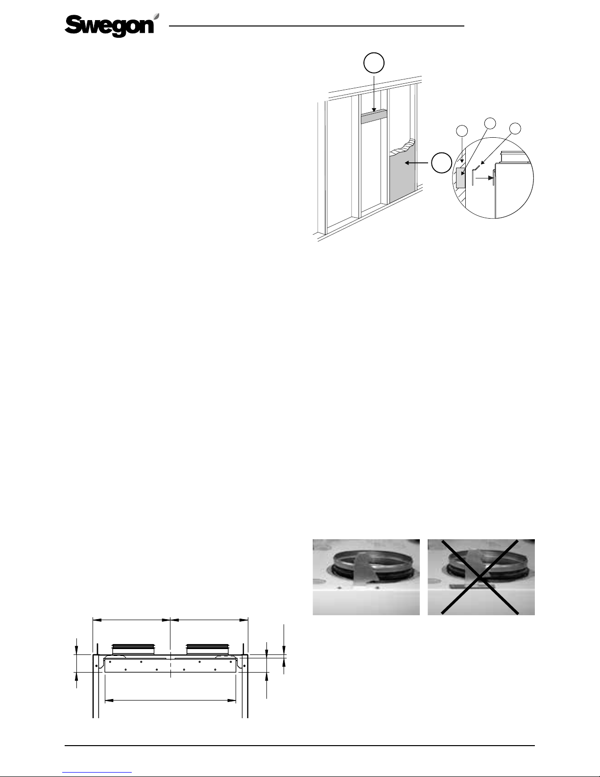
2.1.2 Ceiling mounting
The ventilation unit can also be mounted in a ceiling
mounting frame on the ceiling (can be ordered as an
accessory).
Fasten the ceiling mounting frame in ceiling anchor
sleeves with four M8 threaded rods. The length of rods
must be adjusted so that they will be positioned approx.
15–20 mm under the inner surface of the ceiling
mounting frame. Install the ceiling mounting frame
approx. 35–55 mm below a suspended ceiling.
The ceiling mounting frame must not be used as
part of a support structure for the ducts, the duct
support must be sufficient even without the support
effect provided by the ceiling mounting frame.
Secure the locking hooks in mounting openings on
the ventilation unit’s top side by means of pop rivets.
Position the hooks so that the sharp point is facing the
rear side of the ventilation unit.
The hooks must absolutely not be secured with
rivets directly above the ventilation unit.
The points of the hooks face the rear part of the ventilation
unit and they are to be slipped into the unit’s notches before
you secure them with rivets.
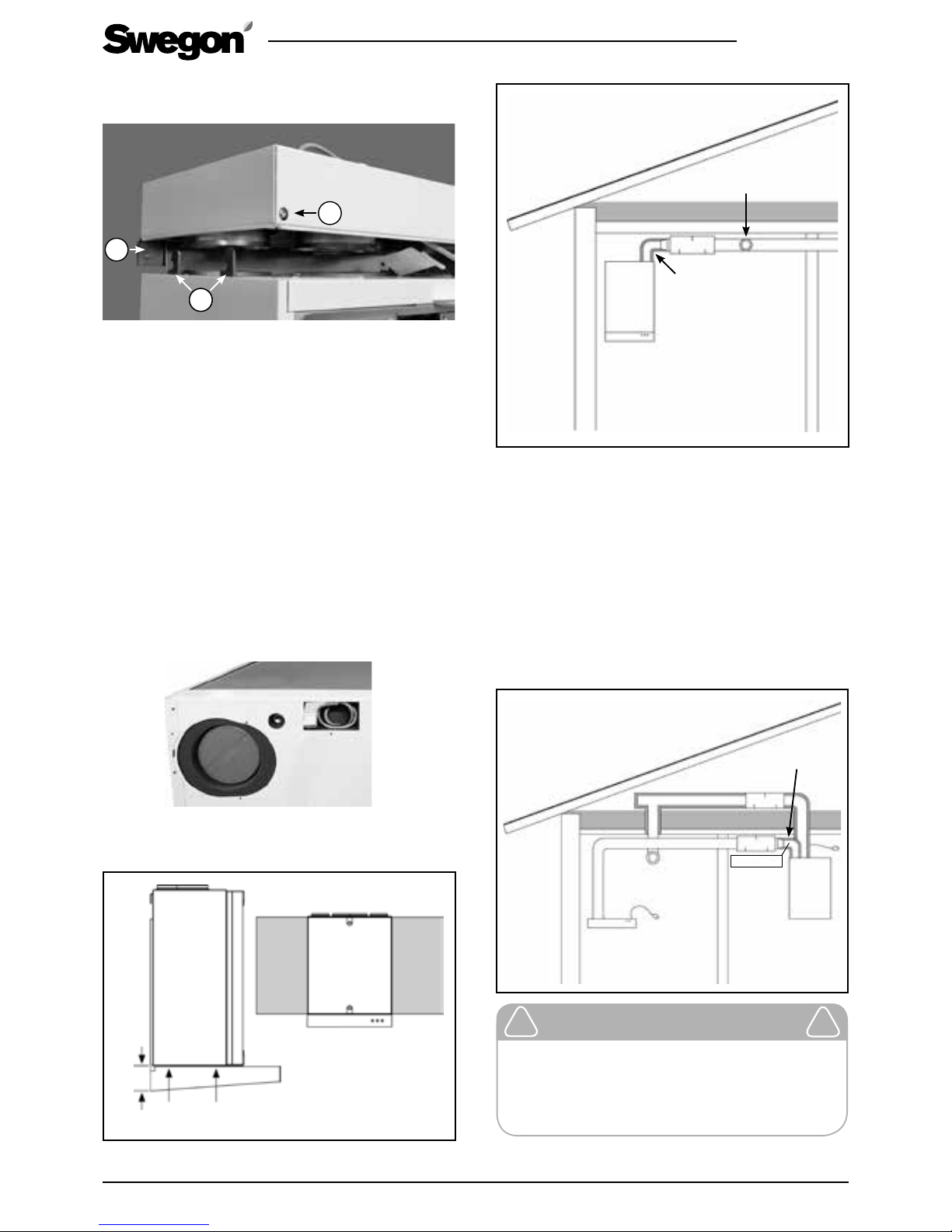
Hang the ventilation unit up in the mounting frame
so that the rear of the unit engages in the suspension
plate. Lift the ventilation unit up against the ceiling
mounting frame so that the locking hooks on both sides
engage into position. The unit is firmly secured if the
screw heads on the front part of the ceiling mounting
frame return to their original positions. The ventilation
2.1 Ventilation unit’s installation site
The temperature in the space where the unit will be
installed must be more than +10 °C. The ventilation unit
can be installed in a machine room, laundry room, store
room, etc.
The ventilation unit can also be mounted in the kitchen
above the cooker. Swegon CASA Jazz cooker hood can
be connected directly to/below the ventilation unit.
Due to the risk of disruptive noise, the ventilation unit
should not be installed on the wall towards the living
room or bedroom.
Make sure it is easy to access the power and control
cables as well as accessories.
The ventilation unit can be mounted either on the wall
with a wall mounting bracket included in the supply or
on the ceiling with a ceiling mounting frame which is
available as an optional extra.
The unit should be mounted as near as possible to a
wall or ceiling. The space between the ventilation unit
and the wall/ceiling must be insulated to prevent the
transmission of sound through the wall behind the unit
to the adjacent room.
2.1.1 Wall mounting
A wall mount is supplied together with the ventilation
unit.
If it is a question of a light partition wall, the wall must
be reinforced with horizontal studs that support the
weight of the ventilation wall. In addition, Swegon also
recommends that the wall be insulated with mineral
wool or similar insulation for preventing sound from
propagating to other rooms.
Screw the wall mount firmly in horizontal position onto
the wall where a wall stud will support the weight
of the unit. Lift up the ventilation unit onto the wall
mounting bracket so that the ears on the bracket
engage in the corresponding notches at the top on the
backside of the unit.
The door of the ventilation unit and the fans can be
dismantled to facilitate lifting the ventilation unit. See
the ”Servicing” Section.
2. Installation
1
2
1. Horizontal stud for the ventilation
unit’s mounting bracket
2. Acoustic insulation
1
2
3
1. Insulated wall
2. Horizontal stud
3. Wall mounting
bracket
Wall mounting bracket’s dimensions
299 299
505
68
54
14
Page 7
R2.060219
All rights to changes reserved.
7
www.swegon.com
unit can then be secured into position by screwing in
the locking screws to their end positions.
1
2
3
1. Suspension plate
2. Locking hooks
3. Lock screw
2.1.3 Installation of the cooker hood directly on
the ventilation unit
Swegon CASA Jazz cooker hood can be connected
directly below the ventilation unit. In this case, a twosocket socket is required. Make sure that the spacing
between the cooker hood and cooker corresponds with
local regulations.
Connect the control and power cables that come out
of the bottom of the ventilation unit to the connector
on the cooker hood. Secure the cooker hood to the
ventilation unit with the screws supplied.
The ventilation unit can be controlled from the cooker
hood control panel.
The electric and control cables as well as the connection
for the cooker hood’s extract air are located under the
cover plates in the bottom of the unit.
99 mm
The fan’s
mounting screws
The kitchen airflow from the
cooker hood during operation in
the boosted flow mode
Condensation/sound
insulation
The kitchen’s general
ventilation via extract air
register
∅ 125 mm
2.1.4 Installation of the cooker hood separately
from the ventilation unit
All compatible Swegon CASA cooker hoods can be
mounted separately from the ventilation unit, the
extract air is then led from the cooker hood via a duct to
an extra duct connection on the top of the ventilation
unit. The duct between the cooker hood and the
ventilation unit must be installed in such a way that
makes it possible to clean it.
The ventilation unit can be controlled from the cooker
hood control panel.
∅ 100 mm
∅ 125 mm
∅ 125 mm
The kitchen’s general
ventilation via extract
air register
The kitchen airflow from
the cooker hood during
operation in the boosted
flow mode
Condensation/sound
insulation
Important
The 100 mm duct outlet on the kitchen
bypass should be fitted with a taper piece
for transition to 125 mm as near to the unit
as possible.
!
!
Page 8
8
R2.060219
All rights to changes reserved.www.swegon.com
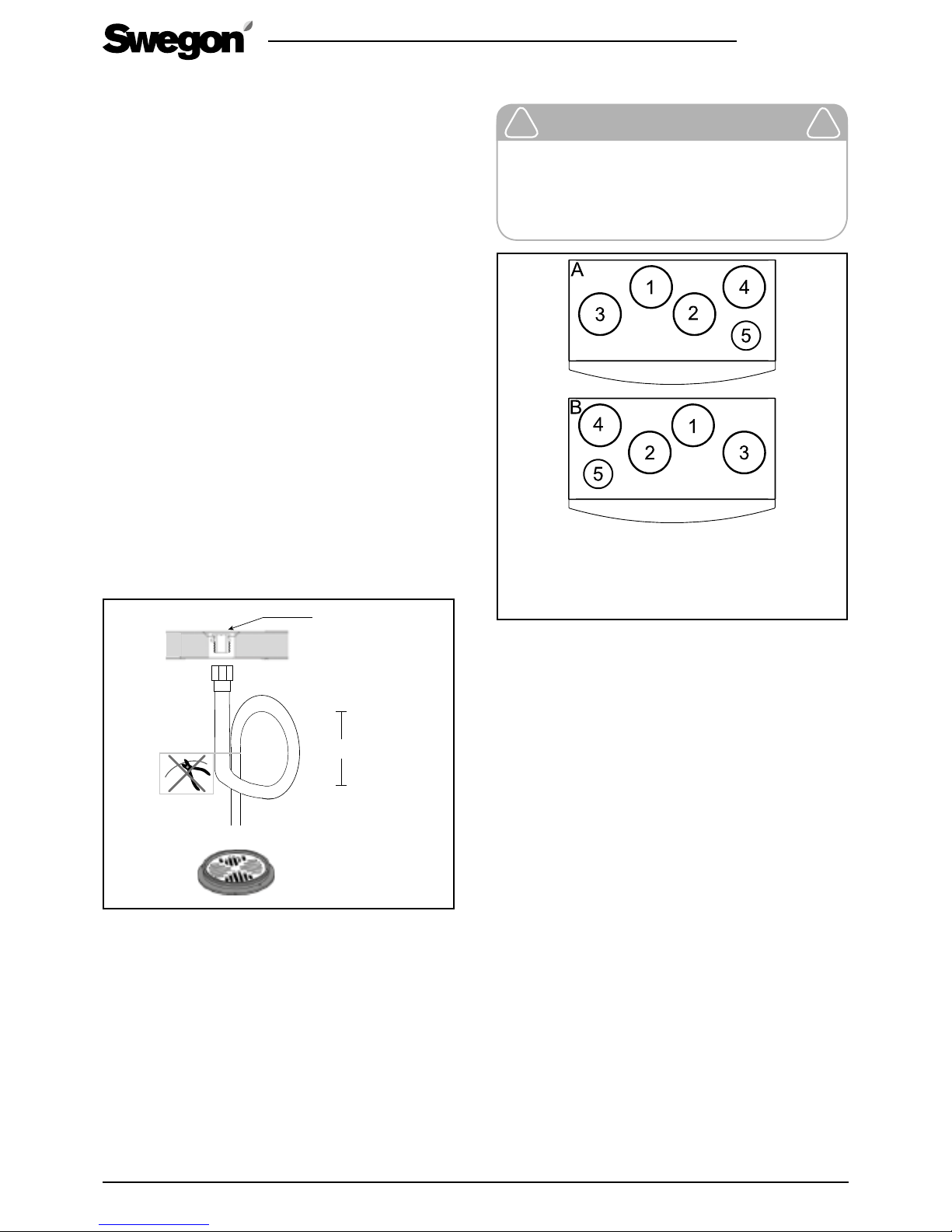
2.2 Condensate discharge
As a rule, no condensate discharge connection
is needed under dry ambient conditions and in
combination with a rotary heat exchanger. A certain
humidity load exists in homes and a condensate
discharge line should be connected to the ventilation
unit, if considerable moisture is produced in the home.
Connect the discharge hose to the ventilation unit’s
condensate discharge connection (3/8” male threads).
The condensate must be channelled to a floor drain,
the water trap of a sink or the equivalent by means of
a tube or a pipe having an inner diameter of at least 12
mm. The tube must not be connected directly to the
sewer. The tube must not have a second water trap or
be run horizontally. The damming height of the water
trap should be at least 100 mm.
The condensate discharge connection is plugged
from the outside of the ventilation unit. Remove
the plug when you begin using the condensate
discharge connection. Check that the condensate
discharge outlet is not clogged and check its outflow
by pouring water on the bottom of the ventilation unit.
The condensate discharge connection is located on the
rear of the unit under the rotary heat exchanger.
A hose to lead off the condensate is available as an
accessory (product: CDH3). The hose has a ready-made
loop that serves as a water trap.
200 mm
3/8" male
thread
There is a metal water trap available as an accessory
(UVL).
2.3 Ducts
Important
Check whether the ventilation unit is in
a left or right-hand version, to be sure to
connect the ventilation ducts to the correct
duct connections.
!
!
A. Right-hand version
B. Left-hand version
1. Supply air
2. Extract air
3. Outdoor air
4. Exhaust air
5. Extract air from the cooker hood
Install the ducts according to the ventilation drawings.
Do not mount ducts directly against structural elements
to avoid the propagation of sound.
Insulate the ventilation ducts to prevent leakage of heat,
cold and sound, as well as water condensing. Fire insulate
the ducts according to national regulations. Pay particular
attention to insulate cold ducts without gaps in the
insulation, so that moisture cannot condense.
The thickness of the insulation must be sufficient for the
insulation material, for the climate area and according
to local regulations. Most manufacturers of insulation
material offer calculation programs for the calculation of
correct and sufficient insulation.
Supply air duct should be fitted with acoustic insulation
along the stretch between the unit duct outlet and
the sound attenuator, so that fan sound will not be
propagated out into the room.
Generally, ventilation ducts should be insulated as follows:
• Insulate the outdoor ducts that pass through warm
spaces.
• Exhaust air ducts should always be insulated in
accordance with national regulations.
• Insulate supply air ducts in cold spaces.
• Insulate extract air ducts in cold spaces.
• If the air inside the duct is colder than in the
surroundings; the insulation should be protected by a
vapour barrier.
Page 9
R2.060219
All rights to changes reserved.
9
www.swegon.com
It is important to the ensure the tightness of the vapour
barrier at the penetration collars. We recommend the
use of a mounting frame with vapour barrier designed
for the ventilation unit (accessory, PR085YP) for sealing
the vapour barrier.
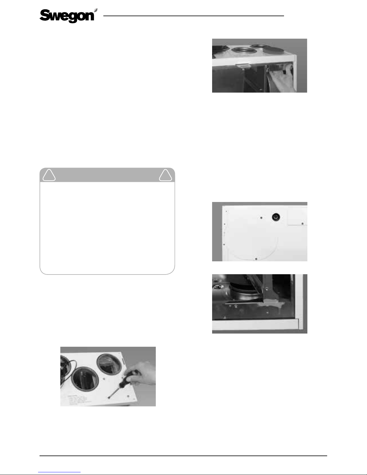
2.3.1 Commissioning the bypass for the kitchen
The ventilation unit has extra duct connections for
extract air from the cooker hood on its top and
bottom sides. The extract air from the cooker hood
flows directly out through the unit’s extract air fan and
does not pass the heat exchanger. For this reason, the
kitchen's general ventilation must not take place via the
cooker hood. On delivery, both of the duct outlets that
bypass the heat exchanger are fitted with covers.
If the duct connection designed for bypass from the
kitchen is used, the duct between the cooker hood and
the unit must be installed in such a way that makes it
possible to clean it.
Important
The kitchen bypass is intended for use
when the air flows from the cooker hood/
kitchen are boosted. The kitchen’s general
ventilation must take place via the extract
air duct. If the general ventilation takes
place continuously via the cooker hood, the
supply air and extract air flows through the
heat exchanger will be out of balance, and
this will lower the efficiency and impair
the ventilation unit’s anti-freeze protection
functions during the winter.
!
!
Dismantle the cover panel on the top of the
ventilation unit
How to open the ventilation unit and remove the guard
plates are described in the section entitled: ”Service”.
• Open the ventilation unit’s inspection door and
remove the guard plates in front of the heat
exchanger.
• Remove the screws of the guard plate that covers the
duct connection.
• Pull out the cover together with its insulation.
• Secure the guard plates for the extract air fan and
the heat exchanger with screws at their positions
and close the inspection door. The duct connection
spigots are now ready for connection to ducting.
Dismantle the cover panel on the bottom of the
ventilation unit
How to open the ventilation unit as well as how to
remove the guard plates and heat exchanger are
described in the Section entitled: ”Service”.
• Open the ventilation unit’s inspection door and
remove the heat exchanger guard plates. Withdraw
the heat exchanger from the unit.
• Remove the screws of the guard plate that covers the
duct connection.
• Pull out the cover together with its insulation.
• Push the heat exchanger back into the unit, secure
the guard plate with screws at its position and close
the inspection door.
Page 10
10
R2.060219
All rights to changes reserved.www.swegon.com
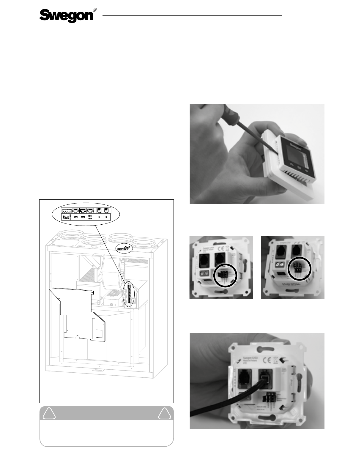
2.4 Electric and control cables
The ventilation unit has a power cable with earthed plug.
The plug serves as the ventilation nit’s main switch and
should be connected to an easily accessible wall socket.
There is a modular cable on top of the ventilation unit
to control the unit. The modular cable for the cooker
hood is located under the cover plate at the bottom
of the ventilation unit. The maximum length of the
modular cable is 40 metres. If you route the modular
cable within a building element, the cable must be
routed in a ∅ 20 mm conduit, bearing in mind any
subsequent cable replacement.
Ensure during the installation of the ventilation unit that
it is easy to access the cable connectors, among others,
for servicing and setting up.
Accessories are either connected to the ventilation
unit’s four-way connector (2 extra functions) or to the
external connection modules (3 extra functions). The
cables are routed through the cable entries that are
inside and on top of the ventilation unit. The connection
of accessories is described in the section “External
connections”. Connection cables to connection modules
and accessories are not included in the supply.
A. Cable entry for accessory cables.
B. Terminal blocks for connection of accessories.
B
A
Important
According to national regulations only a
qualified electrician may carry out electrical
installations.
!
!
2.5 Installation of the Smart control panel
A maximum of two Smart control panels can be connected to the ventilation unit. These should be configured with different ID numbers (Settings/Display/
Display ID). A Smart control panel can be mounted up
to 40 metres from the unit (using 2 x 20 metre long
modular cables).
The front panel on the Smart control panel is released
using a screwdriver to push the retaining clips through
the holes on either side.
If several control panels are connected in chain, the
middle panel’s bus termination is moved to the “Open”
position. The jumpers do not need to be adjusted if only
one control panel is used.
The modular cable can be connected to any outlet
socket on the panel.
Finally, refit the front panel.
Bus termination: OpenBus termination: Terminated
Page 11
R2.060219
All rights to changes reserved.
11
www.swegon.com
2.6 Accessories
Installation instructions for accessories are included in
the delivery of the each product.
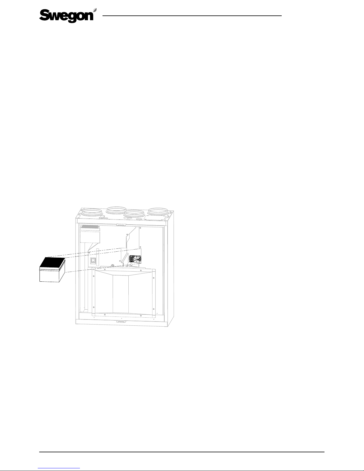
2.6.1 Smart sensor package
Smart Sensor package is a combination sensor:
• Humidity sensor (SRH)
• Humidity and carbon dioxide sensor (SRHCO2)
• Humidity sensor and VOC sensor (SRHVOC).
The ventilation unit has a connection cable for the
sensor package. The sensor package is attached using
the supplied screw. On the R3 ventilation unit, the
installation position for the Sensor package is located
under the extract air filters in the extract air chamber.
The position of the sensor package in the ventilation
unit is shown in the image below. The extract air filter
must be dismantled from the ventilation unit while the
installation is performed.
All sensor combinations are encapsulated in the same
way. If there is a sensor package version installed in the
ventilation unit, you can replace it with an optional
sensor package. See the section Functions and use for
information about the sensor functions.
Page 12
12
R2.060219
All rights to changes reserved.www.swegon.com
3. Basic commissioning
Commissioning is made from the password-protected
“Settings” menu on a Smart control panel. To open the
menu, enter code 1234. (The code can be changed).
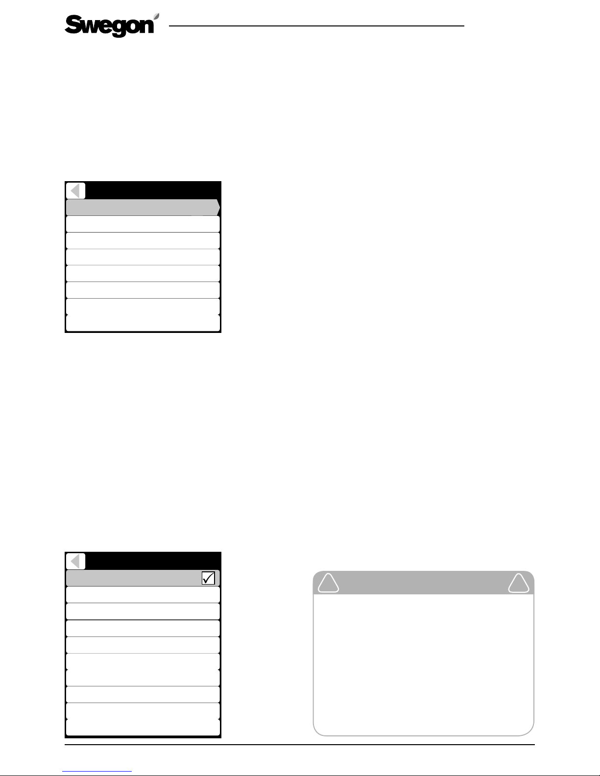
Settings
Airflow adjustments
IO controls
Smart functions
Heating / Cooling
Defrost settings
Modbus
Reset factory settings
Change service code
3.1 Air flows
Particular airflows should be found from house
ventilation plan. The units air flow curves are found in
the section “Technical data”. A qualified person should
adjust the ventilation air flows with the help of measurement
equipment so that they correspond with the ventilation plan.
Air flows for all basic operating modes must be set
so that the ventilation unit works correctly! Enter
the settings in the commissioning report.
Before you start to adjust the air flows, ensure that the
filters are clean and that there are no foreign objects or
debris inside the ventilation unit.
3.1.1 Setting the basic air flows
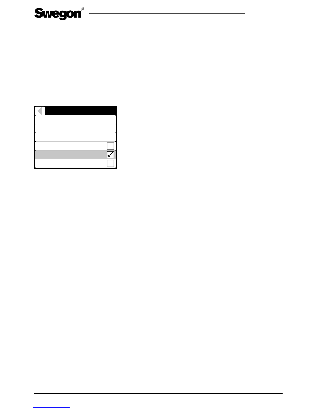
Choose commissioning mode. The ventilation unit’s fans
run at the selected speed and functions, such as anti-freeze
protection and heat exchanger by-pass, are disabled.
Airflow adjustments
Commissioning mode
Home (extract)
Away (supply)
Away (extract)
Boost (supply)
Boost (extract)
Travelling (supply)
Max Smart boost (supply)
50%
35%
38%
90%
92%
35%
82%
Control type Fan control
Home (supply) 48%
Adjust the fan control (%) for the operating modes
Home, Away and Boost so that the planned air flow
rates are reached.
3.1.2 Travelling
Travelling mode reduces ventilation unit’s power consumption. Travelling mode can be used when the home
is empty for long periods.
Adjust the supply fan control (%) for the Travelling
mode. The extract air flow is defined automatically
based on the basic air flows.
3.1.3 Maximum automatic boost
Automatic boost level can be limited if it’s disturbing.
Adjust the supply fan control (%) for the max Smart
boost. The extract air flow is defined automatically
based on the basic air flows.
3.1.4 General notifications
In new homes, there is still construction moisture and the
higher ventilation level is needed to remove the moisture.
If there is a sauna, pool or other moisture producer in
the home, It is recommended to boost ventilation on
demand. This can be managed with Smart humidity
control or active use the ventilation unit’s boost mode.
Before commissioning, all tasks in Installation section must be completed. Before the ventilation system can be taken in
use, the basic supply and extract air flows must be adjusted. If cooker hood is used, the cooker hood function boost air
flow and balancing should be adjusted. If the automatic Home/Away/Boost Smart function is used it must be commissioned, see section 4.
Important
The system should be commissioned by a
qualified person. The air flows must not be
changed by the user, because it could disrupt the ventilation system operation.
Air flows must be adjusted according to the
local regulations.
Never adjust the air flows under the units
specified minimum.
!
!
Page 13
R2.060219
All rights to changes reserved.
13
www.swegon.com
3.2 Cooker hood function
The cooker hood function balances the air flows when the
cooker hood is used. This will help to prevent house negative pressure and improves fume extraction capability. The
ventilation boost level during the function can be defined.
The function starts automatically when the damper in a
Swegon CASA cooker hood is opened or when a cooker
hood defined IO is active.
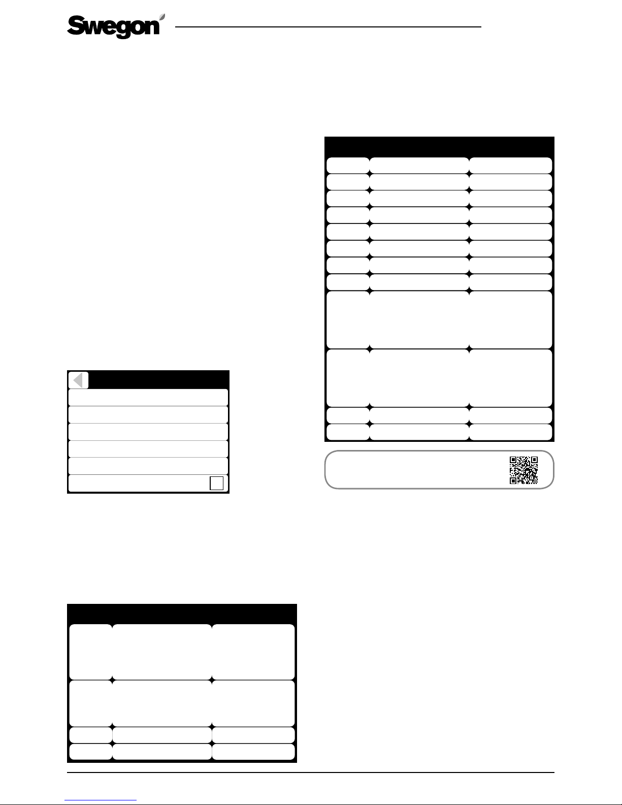
The function and the air flows can be commisioned
from the menu Settings/(1234)/Smart functions/Cooker
hood boost.
Enable the function by selecting it In use.
Cooker hood function
Home state Compensation
Boost state Compensation
10%
Hood boost
0%
Roof fan
85%
In use
Commissioning mode
Choose commissioning mode. The ventilation unit’s fans
run at the selected speed and functions, such as anti-freeze
protection and heat exchanger by-pass, are disabled.
Open the cooker hood damper.
Define the cooker hood air flows in order to adjust
function values.
Home state Compensation. Adjust the Home mode
compensation value so that the supply and extract +
cooker hood air flows are in balance. Compensation
increases supply air flow. (If roof fan compensation is
selected, the extract air flow is first reduced).
Boost state Compensation. Fine tune Boost mode
compensation value if necessary.
Hood boost adjusts the ventilation level during the function, for example, to achieve sufficient discharge velocity
or odour extraction.
Choose Roof fan when using a cooker hood which is
connected to the roof fan. Compensation is achieved by
slowing the extract air fan.
Page 14
14
R2.060219
All rights to changes reserved.www.swegon.com
4. Units external connections
4.1 Modbus
Unit has in build Modbus RTU interface (slave) and it’s
available in a SEC* or SEM* module. SEC IO-extension
cable Modbus interface is designed for single point
connection. SEM IO-extension module Modbus interface
is designed for easy connection to large network with in
and out connectors for A, B and for two shield or ground
connectors.
Installation
Install Modbus network cabling as described in external
connections diagram.
NOTE! Install bus termination to chains last unit (in SEM
use bus terminated jumper, JP1).
NOTE! Shielded cable must be grounded only from one
point (master). SEM has two internally connected connectors for shield/ground chaining.
Settings
Modbus settings can be changed in Settings/(1234)/
Modbus menu.
Modbus
Address
Baud
1
Data bits
38 400
Stop bits
8
Parity
1
Smart Access
None
If Smart Access is connected to the SEC/SEM module
select Smart Access for correct settings. Normally Smart
Access cable should be connected inside electrical box.
Register access
Modbus registers defined in registers list are direct accessible without password. All defined registers are PLC
addresses (base 1). Most commonly used registers are
listed below.
Holding control registers
4x5001
38 400
Operating mode 0 = Stop
1 = Away
2 = Home
3 = Boost
4 = Travelling
4x5018
38 400
Emergency stop 0 = Disabled
1 = Active
2 = Over
pressurising
4x5101 Temperature setpoint°C
4x5406 Reset all alarms 1 = Reset
This section contains information to connect ventilation unit to external devices or system. The unit has in build Modbus
RTU interface to complete control. The units operating modes and functions can be controlled with switch inputs (DI)
or with voltage (0...10 V). The unit state can be monitored from relay outputs or voltage output (0...10 V).
*) Accessory
Input registers
3x6201 Fresh air temperature 0,1 °C
3x6203 Supply air temperature 0,1 °C
3x6204 Extract air temperature 0,1 °C
3x6213 CO2 PPM
3x6214 RH %
3x6217 VOC PPM eqv.
3x6205 Supply fan RPM 1/s
3x6206 Extract fan RPM 1/s
3x6301 Unit state 0 = Ext. stop
1 = User stop
2 = Start
3 = Normal
4 = Commissioning
3x6302 Operating mode 0 = Stop
1 = Away
2 = Home
3 = Boost
4 = Travelling
3x6136 Combined alarm See full list
3x6137 Combined info See full list
Full register list:
www.swegonhomesolutions.com
Page 15

R2.060219
All rights to changes reserved.
15
www.swegon.com
4.2 Switch inputs (DI)
Unit operating modes and functions can be controlled
with switch (digital) inputs. All inputs are configurable to
any operation, and input polarity (NC/NO) can be selected. The unit has two inputs (IO1 and IO2). SEC/SEM*
modules has three inputs more (IO3, IO4 and IO5).
Installation
Install switch devices to selected inputs (IO1-IO5) and
ground.
Settings
IO settings can be changed in Settings/(1234)/IO controls
menu. Configure input type to switch input. Select active state according to application. Closed selection will
active function when input is connected to ground (NO).
Operations
Select required switch function:
1. Emergency stop
Emergency stop when input active.
2. Stop
Unit stopped when input active.
3. Fireplace
Fireplace function activated by input pulse, function
time defined in Smart settings.
4. Hood
Cooker hood function active when input active.
5. Central vacuum (CVC)
Central vacuum cleaner function active when input
active.
6. Boost force
Boost mode active when input active, overrides
Away mode.
7. Away
Away mode active when input active.
8. Boost
Boost mode active when input active.
9. Modbus (not priority)
Input status can be read from Modbus.
10. Relay control (not priority)
Input status can control relay output.
11. Emergency stop resettable
Emergency stop activation. Emergency stop is reset
from user panel.
12. External alarm.
Alarm indication for external devices.
*) Accessory **) Instructions are supplied with accessory
4.3 Voltage inputs (AI)
Unit operating modes can be controlled with analog
voltage (0...10V) and different sensors can be connected
to voltage inputs. The unit has two inputs (IO1 and IO2).
SEC/SEM* modules has three inputs more (IO3, IO4 and
IO5).
Installation
Install control or sensor cable to selected inputs (IO1-IO5)
and ground.
Settings
IO settings can be changed in Settings/(1234)/IO controls
menu. Configure input type to voltage input.
Operations
Select required analog input function:
1. Operating mode
Operating mode control 0...10 VDC (+/- 0.5 V)
0 V = Control disabled
1 V = Travelling
2 V = Away
5 V = Home
8 V = Boost
10 V = Stopped
2. Operating mode, stepless
Operating mode control 0...10 VDC (+/- 0.5 V)
0 V = Control disabled
1 V = Travelling
2 V = Away
Stepless control between Away and Home
5 V = Home
Stepless control between Home and Boost
8 V = Boost
10 V = Stopped
3. Modbus AI
Analog voltage can be read from Modbus.
4. PA supply air**
5. PA extract air**
6. l/s (supply air)**
7. l/s (extract air)**
8. RH AI**
9. CO
2
AI**
10. VOC AI**
Page 16

16
R2.060219
All rights to changes reserved.www.swegon.com
4.4 Relay outputs
External devices or systems can be controlled with relay
control outputs (+ 24 VDC). The units two inputs (IO1
and IO2) can control external relays. SEM* module has
one inbuilt relay (IO3) and two outputs for external relays
(IO4 and IO5). IO5 is grounding digital output for direct
connection to automation system.
Installation
Install external relay or system according to drawings.
NOTE! The control card can be damaged if you shortcircuit the IO connection selected by the relay output.
Settings
Relay settings can be changed in Settings/(1234)/IO con-
trols menu. Configure input type to relay output. Select
active state according to application. Closed selection
will close/activate the relay output when function is
active (NO).
Operations
Select required relay function:
1. Damper
Output is active when unit is running.
2. Away
Output is active when unit is in Away mode.
3. Boost
Output is active when unit is in Boost mode.
4. Modbus
Output is controlled with Modbus.
5. DI control
Output is controlled with digital input. Switch input
must be defined as relay control. Relay output minimum and/or maximum active time can be defined
from IO controls menu.
6. Manual on
Output is always on.
7. Travelling
Output is active when unit is in Travelling mode.
8. Service.
Output is active when service reminder is active.
9. Critical alarm
Output is active when critical alarm is active. Unit is
operating in restricted mode.
10. Alarm
Output is active when any alarm is active.
4.5 Voltage outputs (AO)
External devices or systems can be controlled with analog
output (0...10 V). SEM/SEC* module has one analog
output (AO4).
Installation
Install device or control cable to AO4 and ground.
Settings
IO settings can be changed in Settings/(1234)/IO con-
trols/AO4 menu.
Operations
Select required output function:
1. Operating mode
Operating mode output 0...10 VDC
0 V = NA
1 V = Travelling
2 V = Away
5 V = Home
8 V = Boost
10 V = Stopped
2. Operating mode, stepless
Operating mode output 0...10 VDC
0 V = Control disabled
1 V = Travelling
2 V = Away
Stepless output between Away and Home
5 V = Home
Stepless output between Home and Boost
8 V = Boost
10 V = Stopped
3. Temperature setpoint
Temperature setpoint (10-30 °C) corresponds to 0...10 V.
4. Modbus
Output is controlled with Modbus.
4.6 Smart Access
Unit can be controlled, monitored and commissioned
with web service Smart Access*. Smart Access allows
automatic alarm and service notifications through email.
Smart Access provides unit specified links to spare parts
and filter web shop and to Casahelp.
Installation
Install Smart Access device cable to unit internal connector or connect cable to SEC/SEM (Modbus and IO4).
Connect Smart Access to public internet with ethernet
cable (ETH connector).
Settings
If Smart Access is connected to internal connector no
settings are required.
If Smart Access is connected to SEC/SEM module select
Smart Access enabled in Settings/(1234)/Modbus menu.
Operations
Read the QR code from Smart Access device with smart
device and follow the instructions.
*) Accessory
Smart Access:
More information
Page 17
R2.060219
All rights to changes reserved.
17
www.swegon.com
IO2
IO1
GND
24V / (5V)
8
9
A1
A2
A1
A2
2 x 0,5
2 x 0,5
5-24V
IO5
IO1-IO4
GND
3
2
BUS TERMINATIONBUS TERMINATION
5
4
10
102TKC
2 x 0,5
IO1 - IO5
GND
11
2
1
3
117KHH
2 x 0,5
IO1 - IO5
GND
12
1
NC
2
3
NO
230V AC 50Hz
105A1
2 x 0,5
2 x 1,5
IO1 - IO5
GND
14
G+
G0
OUT1
OUT2
M
Relay
Relay
OUT4
117HDL
4 x 0,5
IO1 - IO5
GND
GND
24V
15
G+
G0
OUT1
OUT2
M
Relay
Relay
OUT4
117HDL
3 x 0,5
IO1 - IO5
GND
24V
13
P
117PK2
2 x 0,5
IO1 - IO5
GND
2
1
3
16
102LT
2 x 0,5
2 x 0,5
IO1 - IO5
GND
IO1 - IO5
GND
24 V
Smart Extension
Modbus module
Smart unit
SEM
Modbus in
8 7 6 5 4 3 2 1
+5VIO5 IO4(IO3) AO4
max 250 V / 6 A
Relay X1
NC
4 3 2 1
NC
1 2 3 4
AB oo
1 2 3 4
AB oo
Modbus out
JP1
Bus
terminated
JP1
SEM
OPEN
TERMINATED
OPEN
TERMINATED
1
7
L
N
2 = Modbus B
1 = Modbus A
3 = IO 3
4 = IO 4
5 = IO 5
6 = AO 4
7 = 5 V Out
8 = GND
SEC
6
1 = GND
2 = AO 4
3 = GND
4 = (IO 3)
5 = IO 4
6 = IO 5
7 = GND
8 = 5 V Out
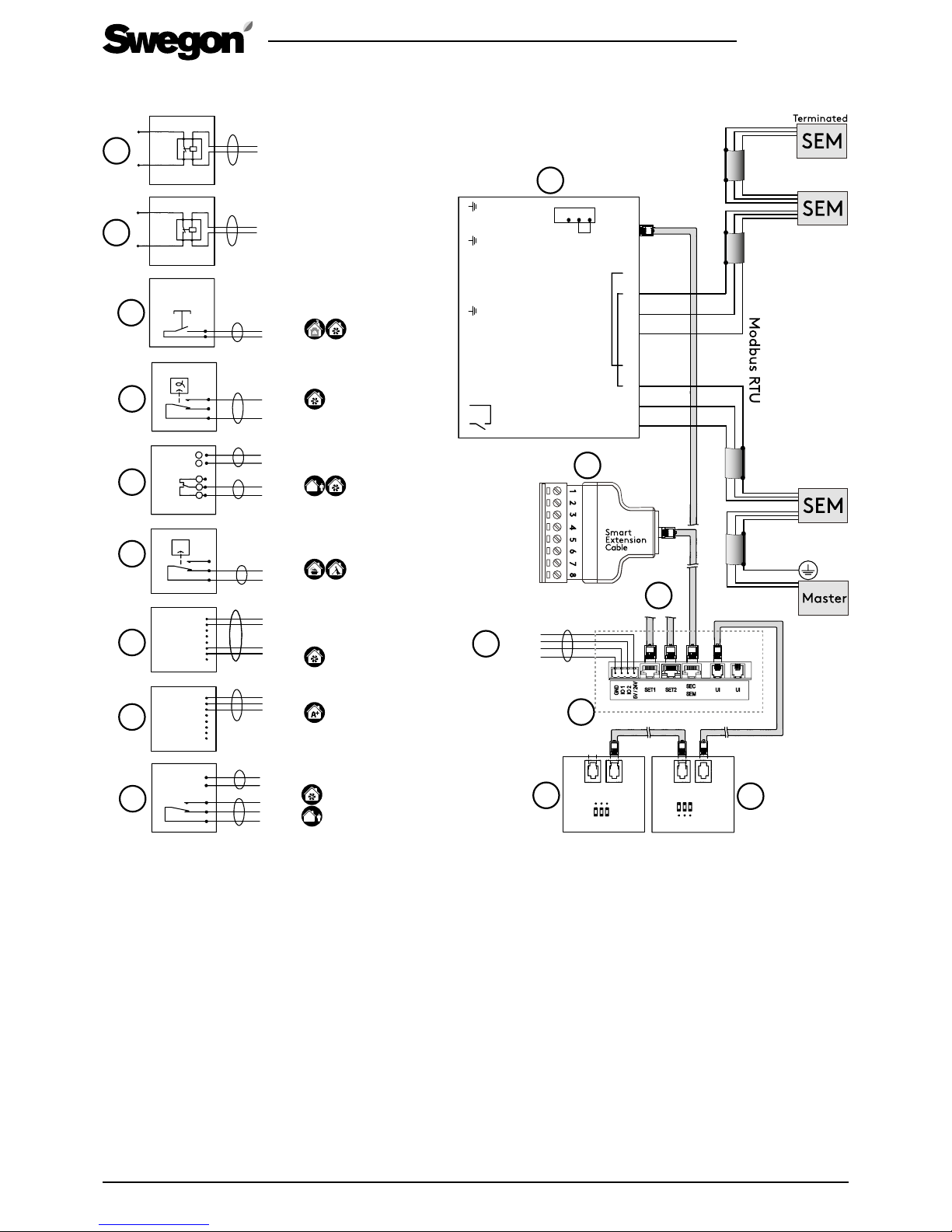
1. Air handling units external connections
2. Swegon CASA Smart control panel (UP1)
3. Swegon CASA Smart control panel (UP2)
4. Connection points on the ventilation unit: IO1, IO2, 24 V / (5 V), selection from circuit board
5. SET-module, Smart Extension Temperature module, connection card for external duct equipment
6. SEC Smart Extension Cable, IO-extension cable with Modbus RTU (single point connector)
7. SEM Smart Extension Modbus module, IO-extension module with relay and Modbus RTU (in and out connectors)
8. External relay control, alarm signal, duct damper, status signal, Modbus
9. External relay control (earthed output), alarm signal, duct damper, status signal, Modbus
10. Fireplace/boost switch, for control of the fireplace function or boosting
11. Humidity sensor, for control of boosting
12. Timer, for control of the Away/Boost mode
13. Pressure switch, for control of the cooker hood/central vacuum cleaner function.
14. CO
2
sensor with relay, for activate the boost mode
15. CO
2
sensor, for control of Automatic Home/Away/Boost system
16. Presence sensor
External connections diagram
Page 18
18
R2.060219
All rights to changes reserved.www.swegon.com
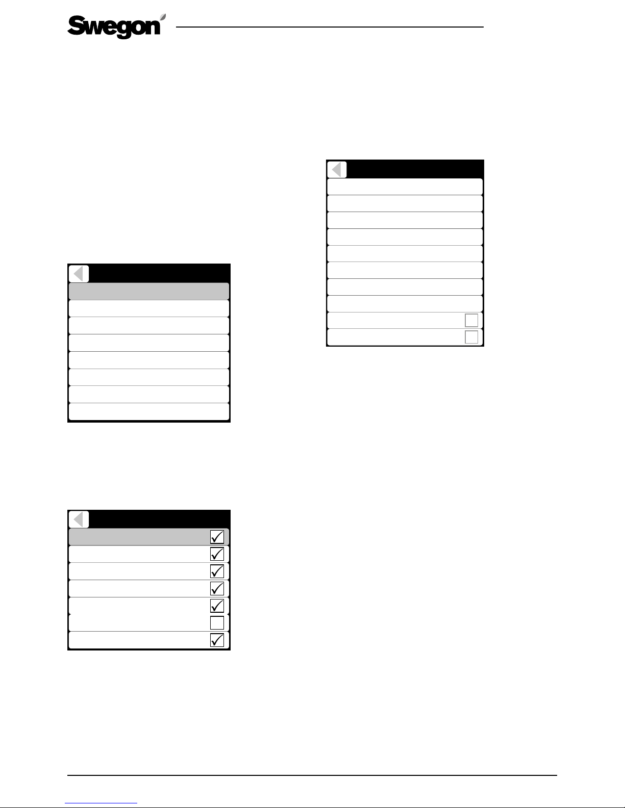
Summer night cooling
Level
Fresh air limit
Fresh air start limit
5°C
User
14°C
Room temperature start limit Off
Supply air limit
Boost
Boost limit (room)
User
14°C
23°C
Full boost limit (room) 26°C
Use in away mode
Hood boost
In the shortcut menu only preset level and Boost are
selectable. To define advanced function settings select
“User”.
Summer night cooling level
Summer night cooling level is defined by cooling need
detection limits and by lowering supply air temperature
setpoint. With preset values the user can select cooling
level: off, low, normal, high or full. Fresh air limit deter-
mines at which outdoor air temperature the function is
allowed.
By default the cooling need is defined by outside temperature calculations and room temperature changes.
If advanced settings (User) is selected the fresh air start
limit can be changed which effects to the cooling detection limits.
If “Room air temperature limit” is selected, the cooling
need is based on fixed room temperature start limit.
The supply air temperature setpoint is defined with
supply air limit during function. If the limit is changed,
the risk of condensation on the pipes must take into
consideration.
Summer night cooling stepless boost
Summer night cooling effect is enhanced with boosting
the ventilation if supply air temperature is relatively low.
With preset values the user can select boosting level:
off, low, normal, high or full.
If advanced settings (User) is selected the boost level can
be defined with room temperature boost limit and full
boost limit.
Select Use in Away mode to allow boost in Away mode.
Select Hood boost to open the damper on CASA Smart
cooker hood when summer night cooling is active.
5.1 Functions
The Smart functions can be activated from the control
panel shortcuts, Modbus or via external inputs. Some of
the functions are so-called background functions which
work by demand. Advanced settings can be accessed
from the “Settings/(1234)/Smart functions” menu.
Note, some settings may not be visible depending units
configuration.
Smart functions
Shortcuts
Summer night cooling
Cooker hood function
Central vacuum function
Fireplace function
Auto Home/Away/Boost
Auto RH control
Auto Air Quality control
5.1.1 Shortcuts
From the “Shortcuts” menu you can set which functions
are to be visible to the user. Boost selection effects to
Auto RH control, Auto air quality, Auto Home/Away/
Boost functions which are available.
Shortcuts
Fireplace function
Travelling
Central vacuum function
Boost
Summer night cooling
Heating boost
Shut down
5.1.2 Summer night cooling
Automatic Summer night cooling detects cooling need
and decreases the supply air temperature, if possible,
and boosts the ventilation. Temperature control is
applied with heat exchanger efficiency control and with
external cooling battery (accessory). Summer night cooling is most efficcient when the outdoor air temperature
is relatively low.
5. Functions and use
This section contains functions detailed description, advanced settings and use. The advanced settings for the functions
can only be accessed from Smart settings with password (1234 / changeable). The normal user settings can be limited.
In the User manual the functions are only covered from the user point of view. User settings are accessed from the
Smart shortcut menu.
Page 19
R2.060219
All rights to changes reserved.
19
www.swegon.com
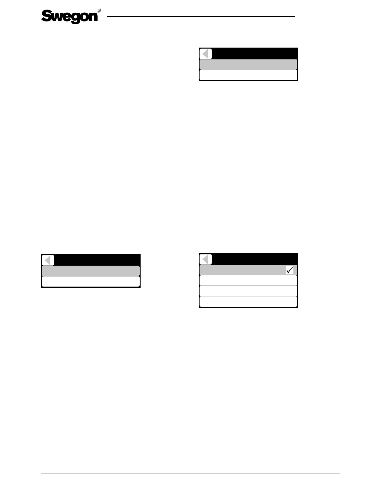
The function’s settings can be adjusted from the
Settings/Smart Functions/Fireplace function menu.
Fireplace function
Run time
Speed difference 15 %
15 min
The function’s maximum level can be adjusted with the
Speed difference setting (max 25 %). The function is
applied by demand with first decreasing the extract air
flow and increasing the supply air flow if needed.
If problems occur with the chimney draught when
lighting the fire, the percentage value can be increased
slightly from the default value.
Use of the fireplace function repeatedly in extreme cold
can cause forming of ice in the ventilation unit.
5.1.6 Automatic Home/Away/Boost function
The function is available only on models equipped with
a CO
2
sensor. The function controls the ventilation
steplessly between away and boost levels by demand.
When the unit is controlled to away mode temperature
setpoint can be decreased to save even more energy.
The function should always be adjusted to ensure optimal performance.
The function can be activated and adjusted from the
Settings/(1234)/Smart Functions/Home/Away/Automatic
Boost menu or from Smart shortcuts menu.
Auto Home/Away/Boost
In use
A+ now
Home limit
Away limit
750 ppm
900 ppm
600 ppm
The function is adjusted by defining the CO2 limits for
Home and Away. When measured CO2 value is between these values the air flow is controlled accordingly
between Away and Home. If CO2 value is above Home
limit the air flow is boosted lineary and if CO2 value is
below Away limit the Away mode is activated.
A suitable Home limit value can be defined by reading
the measured CO
2
level (A+ now) from the menu when
a planned number of people are in the house. Similarly
the Away limit value can be defined by reading the
measured CO2 level (A+ now) from the menu when a
house is empty and the CO2 level is settled.
The ventilation can be raised when people are at home
by decreasing the Home limit. The away mode can be
activated earlier by increasing the Away limit.
NOTE! The function is only visible if the CO
2
sensor has
been detected.
NOTE! Measured CO2 value depends on the ventilation
system but the function is calibrated with the limits.
5.1.3 Cooker hood function
The cooker hood function balances the air flows when the
cooker hood is used. This will help to prevent house negative pressure and improves fume extraction capability. The
ventilation boost level during the function can be defined.
The function starts automatically when the damper in a
Swegon CASA cooker hood is opened or when a cooker
hood defined IO is active.
The balancing is applied with increasing the supply air
flow. If cooker hood is connected to separate extract
duct and roof fan is selected the balancing is first decreasing the extract air flow and increasing the supply
air flow if needed.
Commissioning and settings for the cooker hood function
is described in Basic commissioning section.
5.1.4 Central vacuum function
The central vacuum function balances the air flows
when the a central vacuum cleaner is used. This will
help to prevent house negative pressure and improves
the cleaning result. The function can be started by external switch connected to input configured as the CVC.
The function will then be activated automatically when
the central vacuum is on.
The function can also be started from a Smart control
panel, the function runs until the set time has elapsed
(Run time).
The function’s settings can be adjusted from the Settings/
(1234)/Smart Functions/Central vacuum function menu.
Central vacuum function
Run time
Compensation 20%
30 min
The function's balancing level can be adjusted with
the Compensation setting (max 50 %). The balancing
is applied with first decreasing the extract air flow and
increasing the supply air flow if needed.
5.1.5 Fireplace function
The fireplace function helps lighting the fire and ensures that no excess under pressure is generated. The
function can be started from Smart shortcuts menu or
by external switch connected to input configured as the
fireplace function (IO-control).
Problems caused by too little draught in a fireplace
usually occur in the autumn, when the temperature
difference between the indoor and outdoor air is slight
and the chimney is cold. The Fireplace function attempts
to help the situation by giving a temporary positive pressure in the home when the fireplace is lighted.
After the lighting phase the function prevents the excess
under pressure formation. The function Run time can be
changed from the settings (max. 60 min). The function
can be stopped from the control panel.
Page 20
20
R2.060219
All rights to changes reserved.www.swegon.com
5.1.7 Automatic humidity control
The function is available only on models equipped with
a humidity sensor. The function boosts the ventilation
steplessly by demand. For example if humidity in the
house rises due to showering.
If the humidity level (RH) remains above 60 % for a long
period, we recommend that the ventilation is boosted
and the humidity source is investigated.
The function can be activated and level selected from the
Settings/(1234)/Smart Functions/Auto RH control menu or
from Smart shortcuts menu.
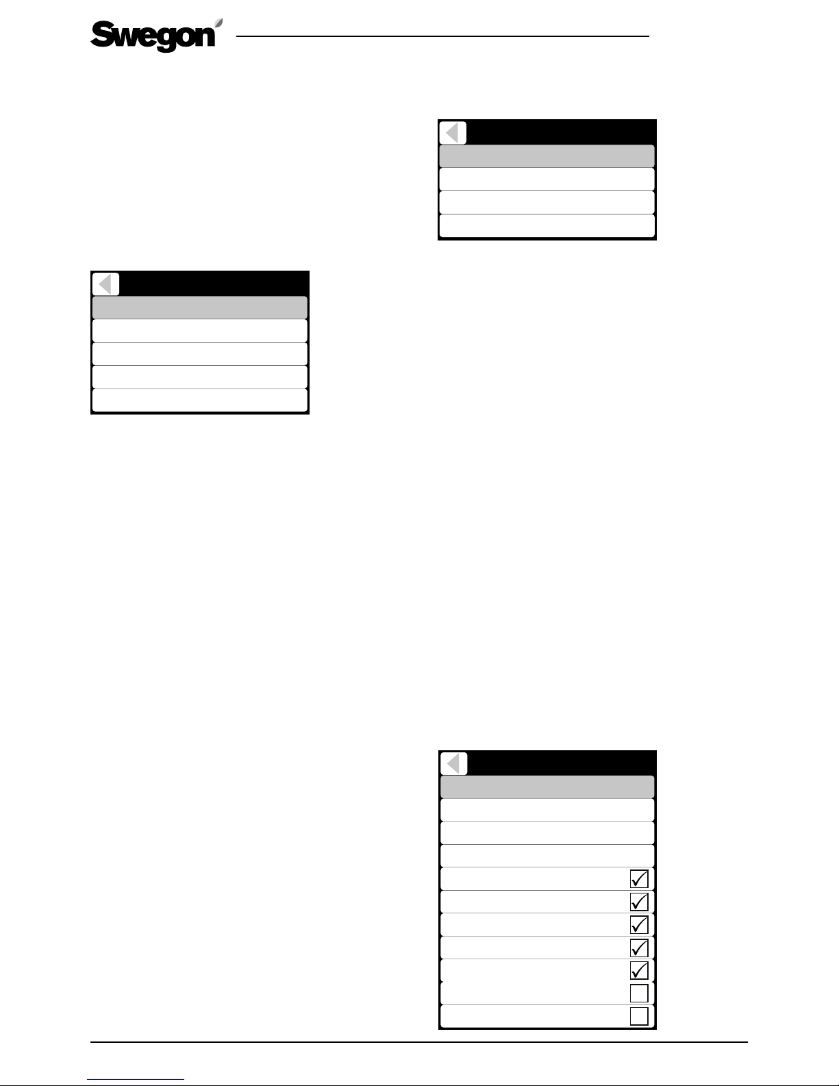
Auto RH control
Level
Boost limit
Full boost limit
Boost delay
30 % + RH
Boost during dela
y5
%
5 % + RH
User
0 min
The user can select preset boost levels in the shortcut
menu (off, low, normal, high or full). The preset levels
define Boost limit and Full boost limit. To define these
limits manually select “User” level.
The ventilation is boosted steplessly when the humidity
has risen from average Boost limit defined amount. The
maximum ventilation boost is reached when the humidity has risen the Full boost limit defined amount from the
average.
The boost can be increased by decreasing the Full boost
limit.
The boost start can be delayed with Boost delay. (The
delay is started when humidity is stabilized after shower or sauna.) Fixed boost level during the delay can be
defined.
NOTE! The function is only visible if the sensor has been
detected. The function is enabled automatically when
the sensor is detected.
NOTE! Humidity is measured from extract air and it
represents average of the whole house.
5.1.8 Automatic air quality control
The function is available only on models equipped with
VOC sensor. The function boosts the ventilation steplessly according to air quality level.
The function can be activated and level selected from
the Settings/(1234)/Smart Functions/Auto Air Quality
control menu or from Smart shortcuts menu.
Auto Air Quality control
Level
AQ now
Boost limit 800 ppm
750 ppm
User
Full boost limit 1500 ppm
The user can select preset boost levels in the shortcut
menu (off, low, normal, high or full). The preset levels
define Boost limit and Full boost limit. To define these
limits manually select “User” level.
The ventilation is boosted steplessly when the VOC has
risen over Boost limit. The maximum ventilation boost is
reached when the VOC has risen to the Full boost limit.
Appropriate values can be established based on the AQ
now value shown in the menu.
The boost can be increased by decreasing the Full boost limit.
NOTE! The function is only visible if the sensor has been
detected.
NOTE! VOC measurement reacts on air quality changes
and absolute value can vary highly but by selecting suitable boost level the function works effectively.
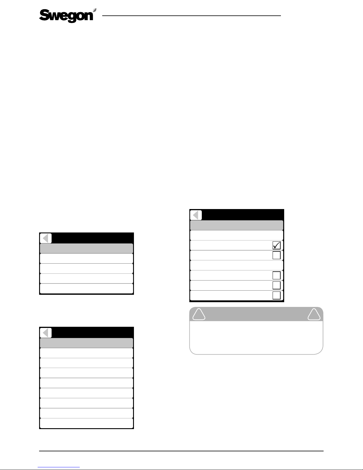
5.1.9 Weekly program
The ventilation unit’s functions can be controlled with a
maximum of four different weekly programs.
Operating mode and temperature for each program can
be selected. Time limits and weekdays for the programs
can be selected.
Smart boost can be disabled for a desired time, e.g.
during the night by selecting Silent mode.
Weekly programs can be enabled and settings can be
made from Main menu/Weekly programs menu.
NOTE! Program 1 has highest priority and program 4
lowest. Highest priority overrides other active programs.
Program 1
State
17°CTemperature
Start time
Stop time
Monday
Tuesday
Wednesday
Thursday
Friday
Saturday
Away
Sunday
07:00
16:00
Page 21
R2.060219
All rights to changes reserved.
21
www.swegon.com
5.2 Supply air temperature control
The supply air temperature is controlled with heat
exchanger and if needed with heating or cooling
element*.
In Comfort mode constant supply air temperature is
maintained by rotor efficiency control and heating or
cooling control.
In Eco mode maximum heating / cooling efficiency is
maintained. Supply air temperature is controlled only in
heating or cooling period.
The temperature control set point can be adjusted from
user panel, weekly timer, by operating mode or controlled by room temperature.
Automatic summer night cooling detects the need
for cooling. Function lowers supply air temperature setting and controls the rotor and cooling coil* to achieve
the best possible cooling effect.
5.2.1 Temperature control settings
The user can change temperature set point from
settings menu. By default temperature setpoint is for
supply air temperature. If room temperature based
control method is selected temperature setpoint defines
preferred room temperature.
Supply temperature control settings can be accessed
from the Settings/(1234)/Heating / Cooling/Supply tem-
perature control menu.
Control method
Control method
Setpoint
Supply air
Setpoint (away)
Setpoint (travelling)
17°C
17°C
16°C
Control mode
ECO
If control method Supply air is selected the base setpoint
and lowered setpoints for Away and Travelling modes
can be set. The heat exchanger Control mode can be
selected.
Control method
Control method
Supply control min value
Room air
Supply controller max value
Cooling min setpoint
17°C
17°C
14°C
Cooling max setpoint
25°C
Setpoint
Setpoint (away)
Setpoint (travelling)
21°C
21°C
20°C
Control mode
ECO
If control method Room air is selected min and max values for heating and cooling (if external cooling device*
is installed) periods can be set. The room temperature
control method aims to control room temperature by
controlling supply air temperature between min and
max values.
The Room temperature setpoint and lowered setpoints
for Away and Travelling modes can be set. The heat
exchanger Control mode can be selected.
NOTE! The Automatic summer night cooling can lower
supply air temperature setpoint.
5.2.2 Temperature measurement
The supply and room temperature measurements can be
fine tuned from settings menu (Settings/(1234)/Heating /
Cooling/Sensors / Controls).
If SET module is attached supply, room, outside or water
radiator temperature sensor inputs can be selected.
5.2.3 External heating & cooling units
Commissioning and setting of the heating and cooling
equipment* connected to the ventilation unit are performed from Settings/(1234)/Heating / Cooling menu.
Detailed instructions are supplied together with accessories. By default the ventilation unit normally has internal
post heating.
Heating / Cooling
Adj. method
Sensors / controls
Supply air
Int. post heater
Ext. post heater
Post heater out limit
Ext. post cooling
Ext. electric preheater
Ext. liquid coil
8°C
Important
Turning off the internal post heating
or lowering the Post heater out limit is
not recommended, due to the risk of
condensation.
!
!
*) Accessory
Page 22
22
R2.060219
All rights to changes reserved.www.swegon.com
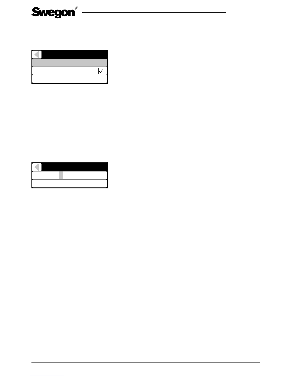
5.3 Anti-frost protection
Anti-frost protection in the ventilation unit works automatically. The level of the anti-frost protection can be
changed from the Settings/(1234)/Defrost settings menu.
Defrost settings
Level
Supply air limit (min.)
14°C
Supply air limit
Normal
Supply air limit function changes airflows if supply air
temperature decreases below minimum limit or below
setpoint.
5.4 Restoring factory settings
Resets all settings made from the control panel, except
commissioned air flows.
5.6 Changing the settings password
Settings password can be changed from Settings/
(1234)/Change service code menu. By changing the
service code commissioned functions can be protected.
Changed password is possible to reset (Casahelp).
Enter code
Accept
[ 1 2 3 4 ]
5.7 Use
The instructions for normal use is described in user manual supplied with the unit.
The unit is designed to work automatically once the
unit is commissioned. Normal use case is that operating
mode is selected. This can be done automatically with
Smart sensors.
Page 23
R2.060219
All rights to changes reserved.
23
www.swegon.com
6.1 Service reminder
The service reminder is activated with preset time
intervals and the symbol is displayed on the control
panel’s screen and cooker hood indication LEDs. As a
factory setting, the service reminder is not in operation.
It can be activated from Main menu/Diagnostics /
Service reminder menu. The recommended service
interval for the ventilation unit is six months.
When servicing has been performed, the service reminder is reset from “Alarm” in the main menu. Service
reminder can always be reset under the main menu item
“Diagnostics / Service reminder”.
Service reminder
Service reminder
Service interval
Next service
Reset counter
6 m
6,0 m
6.2 To open the ventilation unit
Always isolate the power supply by pulling out the plug
from the wall socket before you begin any service work.
Wait a few minutes before you open the inspection
door on the ventilation unit, so that the fan will have
time to stop and the air heaters can cool down.
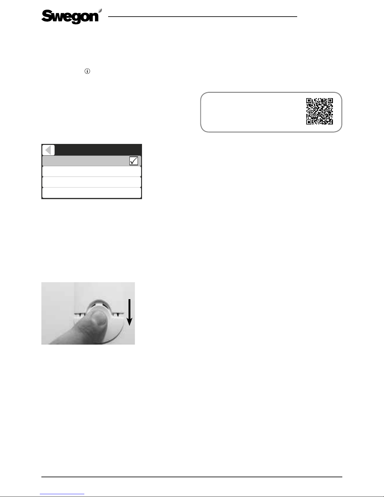
The lock bolts of the inspection doors are located in the
upper and lower edge of the door under the cover plates.
The cover plates can be removed by pressing them in and
sliding to one side as shown in the image below.
Open the inspection door by turning the two lock bolts
with a screw driver for slotted screw heads. The door
can then be carefully lifted off when the lock bolts have
been opened.
Turn the service switch to the 0-position prior to
commencing servicing.
6.3 Filters
The filters should be replaced at least every six months.
The filters may need to be replaced more often in homes
where there is considerable dust or if there are many
impurities in the outdoor air.
In a new home, there is still moisture from the construction
period, and the filters can become soiled more quickly
than usual. The first filter change should therefore be
made more often.
6. Service
The ventilation unit must not be operated without
filters. Use only filters recommended by Swegon.
This is important, as filters with exactly the same
appearance and size can have very different pressure
losses and filter capacity. If an incorrect filter is used, the
ventilation unit may not work as designed and Swegon
can’t be responsible for possible mailfunction. Check
correct filters from the list of components.
How to change filters,
instruction video:
www.swegonhomesolutions.com
Toolbox / How to change a filter
6.4 Heat exchanger
Check the condition of the heat exchanger whenever
you service the unit.
You must ensure that the heat exchanger has not frozen
to the air handling unit’s frame during cold spells. When
necessary the ventilation unit’s inspection door should
be kept open for a time before the heat exchanger is
removed from the unit, so that the temperatures have
time to equalize and to prevent damage to the seals.
Remove the screws of the heat exchanger’s guard plate
and pull the heat exchanger out to inspect it. If you
want to withdraw heat exchanger completely out of the
unit, you must also disconnect the quick-fit connector.
The contact is located under the extract air filter. When
you mount the heat exchanger back in the unit, be
sure to reconnect the connector and arrange the cable
where it won’t become worn by moving parts in the
rotary heat exchanger.
There is an opening in the front plate of the heat
exchanger through which you can see the drive belt.
Carefully rotate the heat exchanger rotor one revolution
to inspect the condition of the drive belt. Do not
damage the heat exchanger fins.
Check the condition of the brushes along the rotor
periphery. Replace the brushes if they are worn.
Make sure that the passages through the heat
exchanger rotor are not clogged and clean them e.g.
with running warm water if required. Never use cleaning
agents. Inside the heat exchanger enclosure there is an
electric motor that must not be exposed to dampness.
The passages of the heat exchanger should be dry
before you reinstall the heat exchanger in the unit.
Page 24
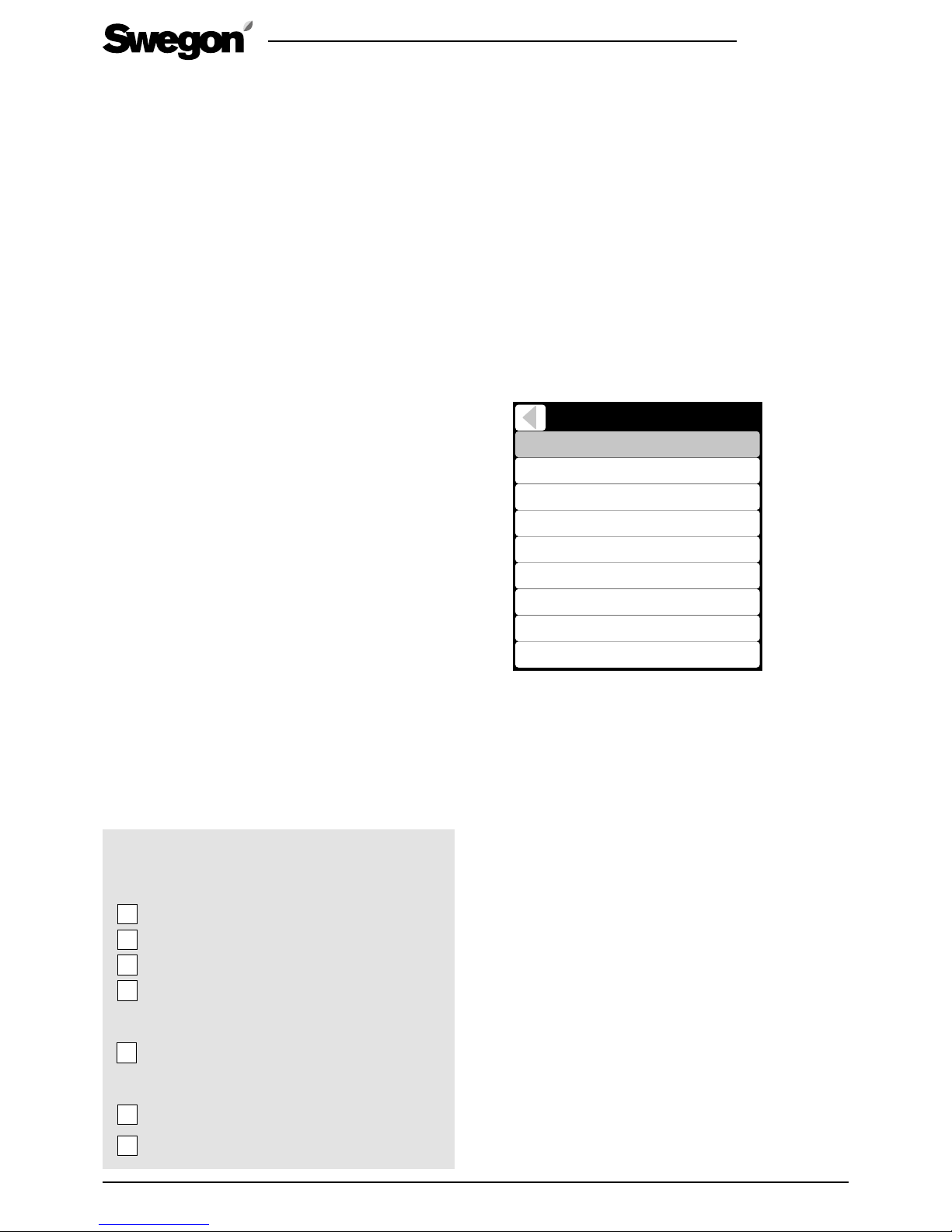
24
R2.060219
All rights to changes reserved.www.swegon.com
6.5 Fans
The ventilation unit’s fans must be checked at least
every two years. In particular, if the cooker hood is
mounted directly on the ventilation unit grease and dust
can accumulate on the extract air fan impeller and on
the walls of the ventilation unit’s fan chamber. If dirt
builds up in the fans this can affect the functionality of
the ventilation unit.
Dismantling the fans from the ventilation unit for
cleaning
• Dismantle the guard plate from the heat exchanger.
• Dismantle the guard plates.
• Remove the fan.
• If necessary, clean with a soft brush. Be careful not
to dislocate the balancing weights. If the fan is very
dirty, allow a professional carry out the cleaning.
• Slide the fan into position.
• Fit the guard plates.
• Fit the guard plate on the heat exchanger.
The ventilation unit fans must be dismantled for
cleaning.
6.6 Other servicing
Clean the interior surfaces of the ventilation unit with a
vacuum cleaner or damp cloth.
Check that the condensate discharge outlet is not
clogged and check its outflow by pouring water on
the bottom of the ventilation unit. The condensate
discharge connection is located on the rear of the unit
under the rotary heat exchanger.
Ensure that dirt has not collected in the air heater, clean
if necessary.
Check that the ventilation unit works normally and that
no alarms are shown on the screen.
Service check list
Every six month
Change filters, reset service reminder
Clean the inner surfaces
Check alarms from user panel
Clean the cooker hood crease filter
Every 2 years
Check and clean fans
Every 10 years
Clean the ducts
Check and adjust the air flows
6.7 Diagnostics
Unit operation can be monitored from Main menu/
Diagnostics menu.
• Service reminder.
Service reminder activation and service interval
setting. The menu also displays the time for the next
service.
• Temperatures.
The temperature values shown in the menu vary
according to which sensors are used in the unit.
NOTE! Fresh air temperature is measured inside
the unit and it may not correspond to outside
temperature.
• Smart functions.
The values shown in the menu vary according to
which Smart sensor is used in the unit.
Smart functions
A+
AQ
RH
AH
AH setpoint
A+ control
RH control
AQ control
830 ppm
770 ppm
41 %
11,8 g/m
-3 %
0 %
4 %
Smart contro
l1
%
3
12,6 g/m
3
The A+, AQ and RH corresponds CO2, VOC and
humidity measurements. The AH an AH setpoint are
absolute humidity values used by auto humidity
control. Humidity boost starts when AH is above AH
setpoint.
The control information shows how much different
automatic Smart functions boost the ventilation with
respect to Home mode. The “Smart control” value
shows the total boost effect for all Smart functions.
• Fan speeds.
The menu shows the fan control values and
measurements.
• Heating and cooling.
The heating and cooling controls, the supply air setting and the supply air temperature are shown on the
menu. In addition, the menu displays indicates the
state of the summer night cooling and preheating.
• Anti-frost protection.
Operating status for automatic defrosting and supply
air limiting.
• External control functions.
The menu includes external input statuses.
Page 25
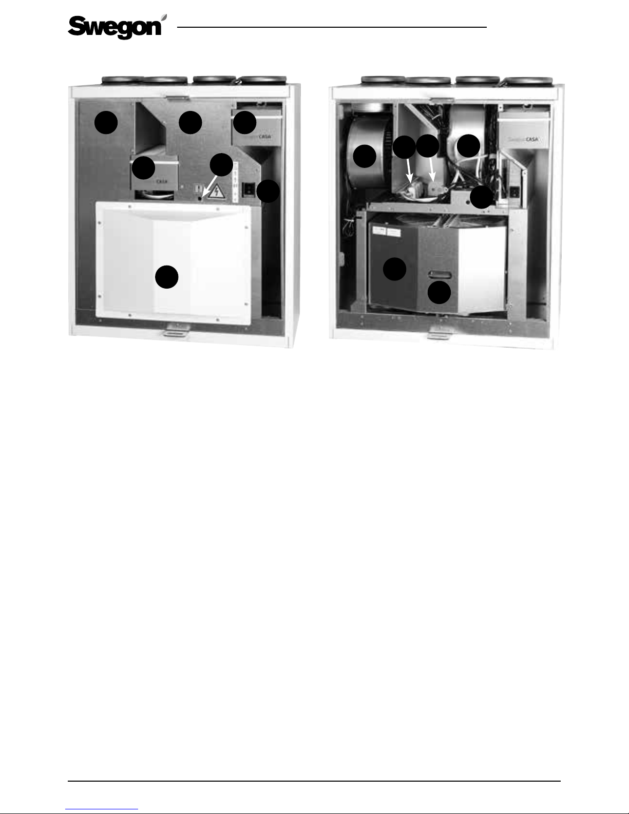
R2.060219
All rights to changes reserved.
25
www.swegon.com
1
Swegon CASA R3 Smart
2
3
5
6
1
2
3
4
5
1. Supply air filter
2. Extract air filter
3. Service switch
4. Resetting the re-heater’s over temperature protection
5. Heat exchanger guard plate
6. Guard plate
4
6
1. Extract air fan
2. Supply air fan
3. Heat exchanger
4. Heat exchanger drive belt
5. Air heaters for reheating
6. Sensor package
7. Heat exchanger’s power connection
6
7
Page 26
26
R2.060219
All rights to changes reserved.www.swegon.com
7. Alarms and Troubleshooting
7.1 Alarm indication, cooker hood
If the ventilation unit detects critical alarm, all signal
lamps on the cooker hood blinks three times every 30
seconds.
Following alarms are indicated:
• Sensor fault
• Supply air hot
• Internal overheat
• Supply air cold
• Water radiator freezing protection shutdown
• Repeating post heater fail
• Repeating preheater fail
NOTE! The service reminder is indicated with one blinking damper timer signal lamp.
7.2 Alarm indication, control panel
If the ventilation unit detects alarm or info message it is
indicated in the user panel main screen. The symbol for
an active alarm is . The malfunction that has caused
the alarm is shown in the menu (Main menu / Alarm).
Info message indicates unconfirmed alarms when the
malfunction is fixed. Info message also indicates the set
service interval has elapsed. The Info message can be
reset from the Alarm menu.
Important
Frost protection function
Ice can form in the heat exchanger during
periods of cold weather if the extract air
is humid. A protective function then automatically reduces the speed of the supply
air fan. Under such conditions, variations in
the fan speed are therefore normal.
Under such conditions, small amounts of
ice can form inside the ventilation unit.
!
!
The unit has inbuild diagnostics for malfunction and protective functions to prevent damage. Malfunction is indicated
with alarm in cooker hood, user interface and with digital relay outputs. This section contains description of alarms, actions and troubleshooting. Most of the actions listed in alarm description table is allowed only for qualified person with
needed permissions.
7.3 Troubleshooting
A ventilation system is composed of several system
components which all influence how the system
operates. A malfunction in ventilation performance
could be caused by any system component or fail in
installation, commissioning or service.
The unit warranty is valid during the warranty period
if unit installation, commissioning and service is done
according this manual. If despite proper usage there are
functional disruptions in the ventilation unit, register
these using the response form at the address www.
casahelp.fi.
There are also instructions, service videos and frequently
asked questions on the same website. You directly
access a web page with model specific instructions by
reading the QR code on the door of the ventilation unit
with a smartphone.
If a problem or a fault occurs on the ventilation system after the warranty period, contact our network of
authorised service companies on www.swegonhomesolutions.com, your real estate company’s service division
or another service company that is fully conversant with
ventilation repairs.
Troubleshooting and service
instructions:
www.casahelp.fi
Page 27
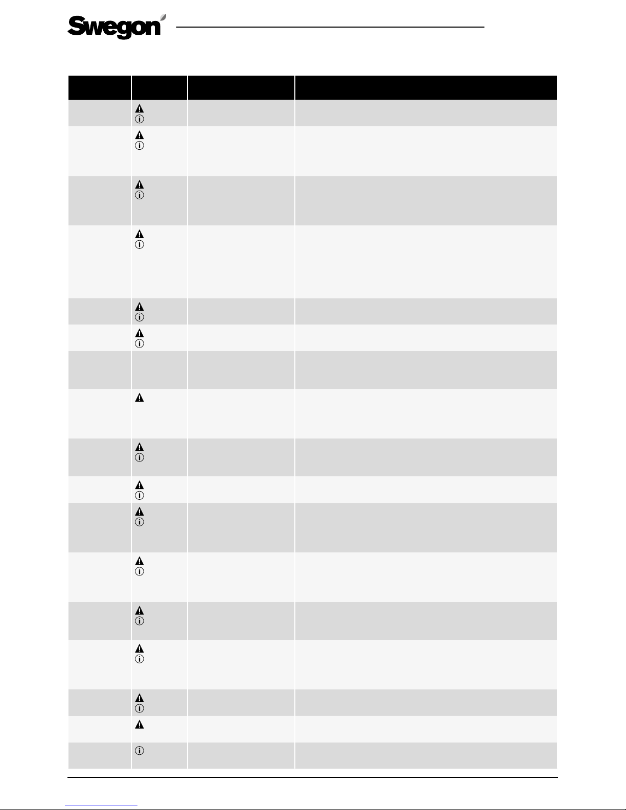
R2.060219
All rights to changes reserved.
27
www.swegon.com
Alarm Modbus
register - bit (LSB)
Cause Action
T1, T2...T9
sensor fault*
3x6136-6
3x6137-6
Sensor reading is out of
range.
The ventilation unit runs in a restricted operating mode. Check
cable connections and configuration. Change sensor if faulty.
Post heater
fail (*)
3x6136-0
3x6137-0
Post heater control diagnostics has detected
open circuit or control
fail.
The ventilation unit runs normally but post heating may not work.
Check manual overheating protection. Check post heating
circuit.
Preheater fail
(*)
3x6136-1
3x6137-1
Preheater control diagnostics has detected
open circuit or control
fail.
The ventilation unit runs normally but preheating may not work.
Check manual overheating protection. Check preheating
circuit.
Water radiator freezing
warning
3x6136-3
3x6137-3
Water temperature is
critically low (12 °C) and
outdoor temperature is
below 0 °C.
The ventilation unit runs normally but freezing protection is activated (electrical heater is activated and valve is fully opened).
If water temperature is below 10 °C the unit is stopped. Unit is
started when water temperature rises over 15 °C.
Ensure that the heating system circulation pump is running
and the water is warm.
Supply fan
fail
3x6136-4
3x6137-4
No fan speed signal. The ventilation unit runs normally.
Check fan and cabling.
Extract fan
fail
3x6136-5
3x6137-5
No fan speed signal. The ventilation unit runs normally.
Check fan and cabling.
Connection
fail
Control panel does
not communicate with
ventilation unit.
Restart the ventilation unit.
Check cabling. Test other connector.
Emergency
stop
3x6136-7
Emergency stop or
emergency stop resettable input activated.
The ventilation unit is stopped by the emergency stop function.
The emergency stop alarm is reset and unit is started when
the input is deactivated.
The emergency stop resettable alarm is reset from user panel.
Internal
failure
3x6136-10
3x6137-10
Internal temperature
critical high. Memory
read error.
The ventilation unit runs in a restricted operating mode.
Restart the ventilation unit.
Rotor fail
3x6136-14
3x6137-14
No rotor speed signal. The ventilation unit runs normally.
Check rotor motor, belt and cabling.
Fan control
3x6136-15
3x6137-15
Constant duct pressure
control error.
The ventilation unit runs normally but without constant duct
pressure control.
Check pressure measurement and settings in commissioning
mode.
Supply air
hot*
3x6136-12
3x6137-12
Supply air temperature
critical high (50 °C).
The ventilation unit runs normally but all electrical heaters are
controlled off.
Inspect the cause for high temperature. Do not use the unit
before problem detected and fixed.
Supply air
cold*
3x6136-11
3x6137-11
Supply air temperature
critical low (10 °C) over
5 minutes.
The ventilation unit is stopped.
The unit is started when supply temperature rises over 10 °C.
Internal
overheat
3x6136-13
3x6137-13
Internal temperature
critical high (50 °C).
The ventilation unit runs normally but all electrical heaters are
controlled off.
Inspect the cause for high temperature. Do not use the unit
before problem detected and fixed.
Elect. preheater fail
3x6136-2
3x6137-2
External electrical preheater control fail.
The ventilation unit runs normally.
Check over heating protection, cabling and settings.
External
alarm
3x6138-1
External alarm input is
active.
The ventilation unit runs normally.
Service
reminder*
3x6137-9
Service interval has
elapsed.
Service the ventilation unit and reset the service reminder.
7.4 Alarm descriptions
*) Indicated in Smart cooker hood
Page 28
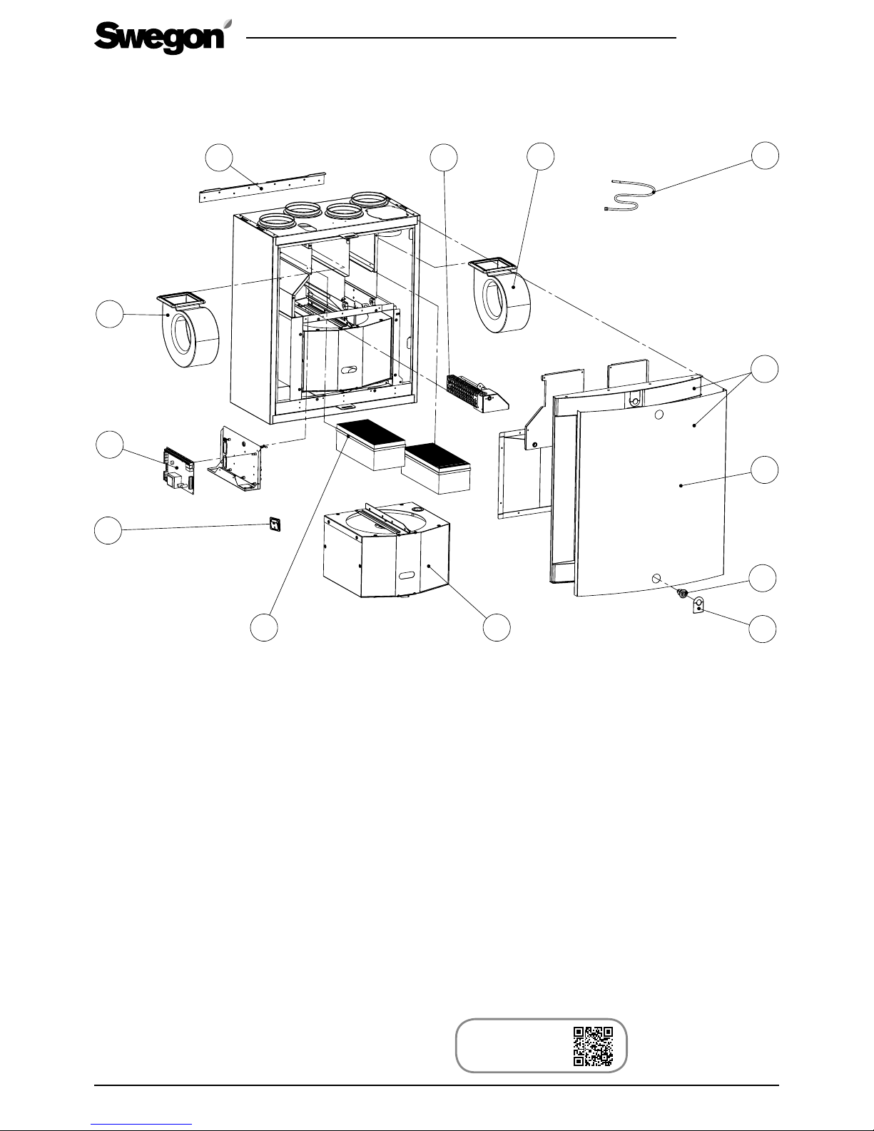
28
R2.060219
All rights to changes reserved.www.swegon.com
Buy online:
www.casabutiken.se
www.casastore.fi
8. Technical data
8.1 List of components
9
10
11
2
2
4
5
6
3
7
8
12
1
1. Temperature sensor *
2. Fan (R Model): PEC119R
2. Fan (L Model): PEC119L
3. Reheating cassette: R3RVM
4. EC circuit card: 6030107
5. Service switch: 50319
6. Set of filters: PR085FS
7. Rotor package (R Model): RP85BR
7. Rotor package (L Model): RP85BL
8. Complete door with white front plate:
DR85BRL1
9. Front plate of the front cover (white): PR085B6V
10. Lock: 61954
11. Cover plate of the lock (white): 61371
12. Wall mounting bracket: WRWMB
Accessories
• Smart control panel: SC10
• Modular cable: PMK20
• Mounting frame with vapour barrier (R/L): PR085YP
• Condensate discharge tube: CDH3
• Water trap: UVL
• Ceiling mounting frame (R): PR085RKA
Ceiling mounting frame (L): PR085LKA
• Set of replacement filters: PR085FS
• Front cover’s cover plate (white): PR085B6V
Front cover’s cover plate (stainless steel): PR085B6R
• Cover plate of the lock (black): 61372
• Swegon CASA Jazz cooker hood for location below
the ventilation unit (stainless steel, white)
• Smart sensor:
- RH: SRH
- RH + CO
2
: SRHCO2
- RH + VOC: SRHVOC
Page 29
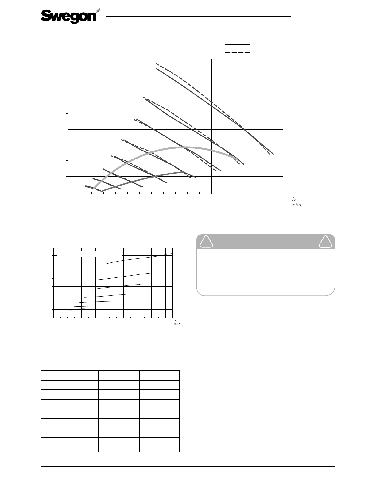
R2.060219
All rights to changes reserved.
29
www.swegon.com
8.2 Air flows (EN 13141-4)
Total capacity, W
Air flow
Power consumption
8.3 Connection outputs
* Swegon CASA Jazz cooker hood connected below R3.
R3 R3 with reheating
Connection 230 V, 50 Hz, 1.0 A 230 V, 50 Hz, 3.2 A
Fans 230 W 230 W
Heat exchanger motor 10 W 10 W
Air heaters for reheating - 500 W
Total output 250 W 750 W
Cooker hood 15 W 15 W
Total output with cooker
hood*
265 W 765 W
0
25
50
75
100
125
150
175
200
225
01020304050607080
100%
90%
80%
70%
60%
50%
40%
30%
03672 108 144 180 216 252 288
Applies to both the fans
0
50
10
0
15
0
20
0
25
0
30
0
35
0
40
0
0102030405060708
09
0
60%
80%
90%
70%
50%
40%
03672 108 144 180 216 252 288 324
100%
30%
SFP 2.0
SFP 1.5
Supply air flow
Extract air flow
Air flow
Pressure differential, Pa
Important
As air flows in Boost mode, you need to
set at least 45 l/s or + 30 % in relation to
the air flow in Home mode, depending on
which of these options gives the greatest
air flow.
!
!
Page 30
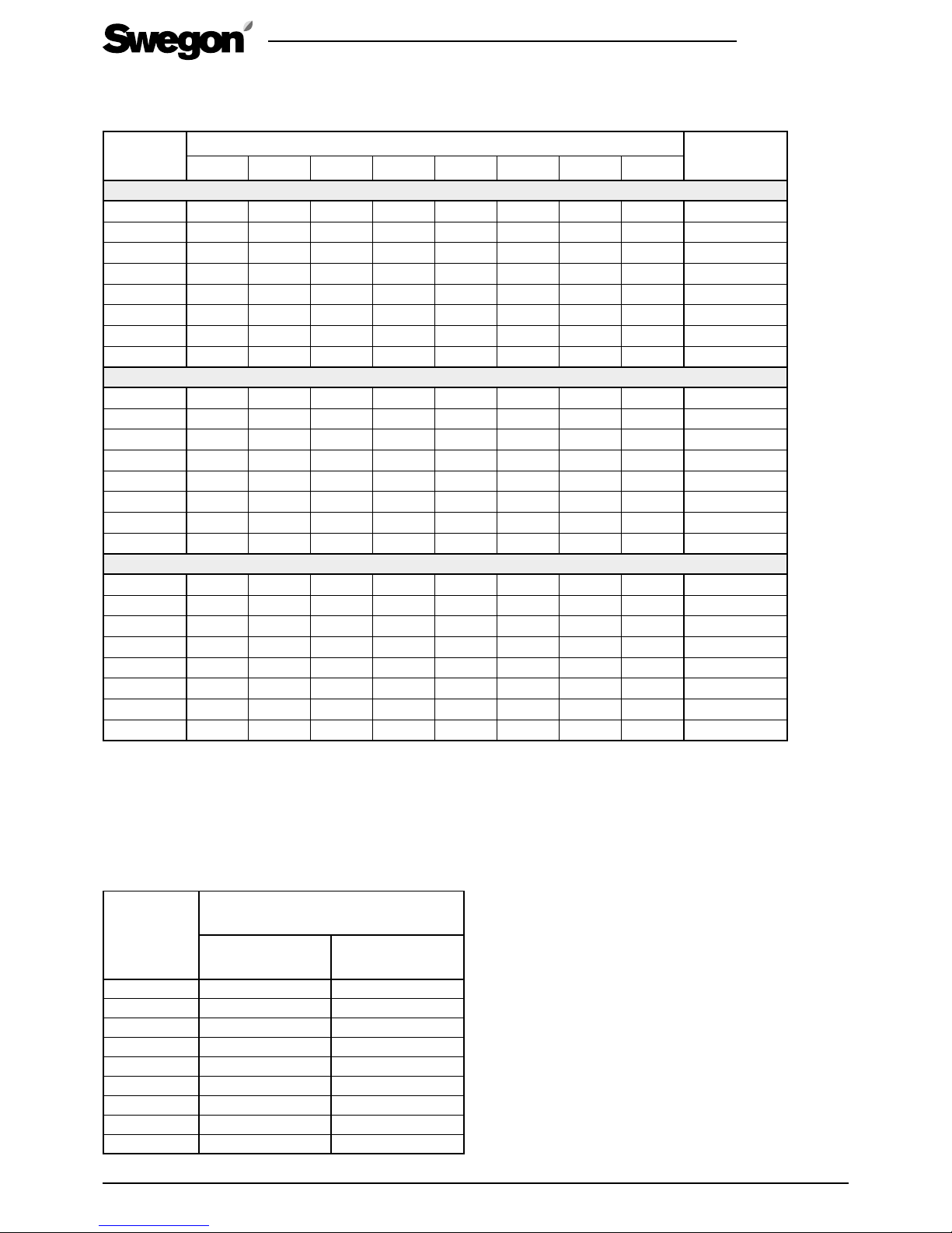
30
R2.060219
All rights to changes reserved.www.swegon.com
Fan setting
%
Sound power level broken down into octave bands, L
wokt
, dB Weighted sound
power level
LWA, dB(A)
63 Hz 125 Hz 250 Hz 500 Hz 1 000 Hz 2 000 Hz 4 000 Hz 8 0 00 Hz
Sound emitted to supply air duct
30
57 44 40 39 34 26 13 - 40
40
60 53 46 45 42 36 26 12 47
50
60 57 49 49 46 41 33 20 51
60
64 63 53 52 50 46 40 28 55
70
68 67 57 56 53 50 45 35 60
80
71 71 61 59 56 54 49 41 63
90
74 75 64 62 58 57 52 45 65
100
77 77 67 64 60 60 55 49 68
Sound emitted to extract air duct
30
57 46 31 29 24 17 12 - 35
40
57 47 36 34 26 18 12 - 37
50
57 47 40 35 27 18 12 - 37
60
58 48 44 39 31 21 14 - 40
70
58 56 48 42 33 24 17 - 45
80
59 62 52 45 35 27 20 - 49
90
60 65 55 48 38 30 23 13 52
100
62 68 57 50 40 32 25 15 55
Sound emitted to kitchen bypass duct
30
60 55 37 33 27 12 - - 41
40
61 56 43 39 33 23 12 - 44
50
59 57 46 42 37 28 19 - 45
60
61 59 51 46 41 33 26 - 49
70
61 63 55 50 44 37 30 16 52
80
67 66 59 53 47 40 35 22 56
90
69 69 62 56 49 43 37 26 59
100
70 72 65 59 51 45 41 30 61
8.4 Acoustic data
Sound emitted to the surroundings
*) Equivalent to a normal dampened room. If values are converted to LWA, dB (A) values, the 4units (dB) need to be added to the table values.
Fan setting
%
Sound pressure level
10 m² sound absorption
L
P
(10), dB(A)*
Mounted between
cabinet together with
the cooker hood
Mounting on a wall
20 22 27
30 23 27
40 24 29
50 25 30
60 30 32
70 31 35
80 34 38
90 36 40
100 40 43
Page 31
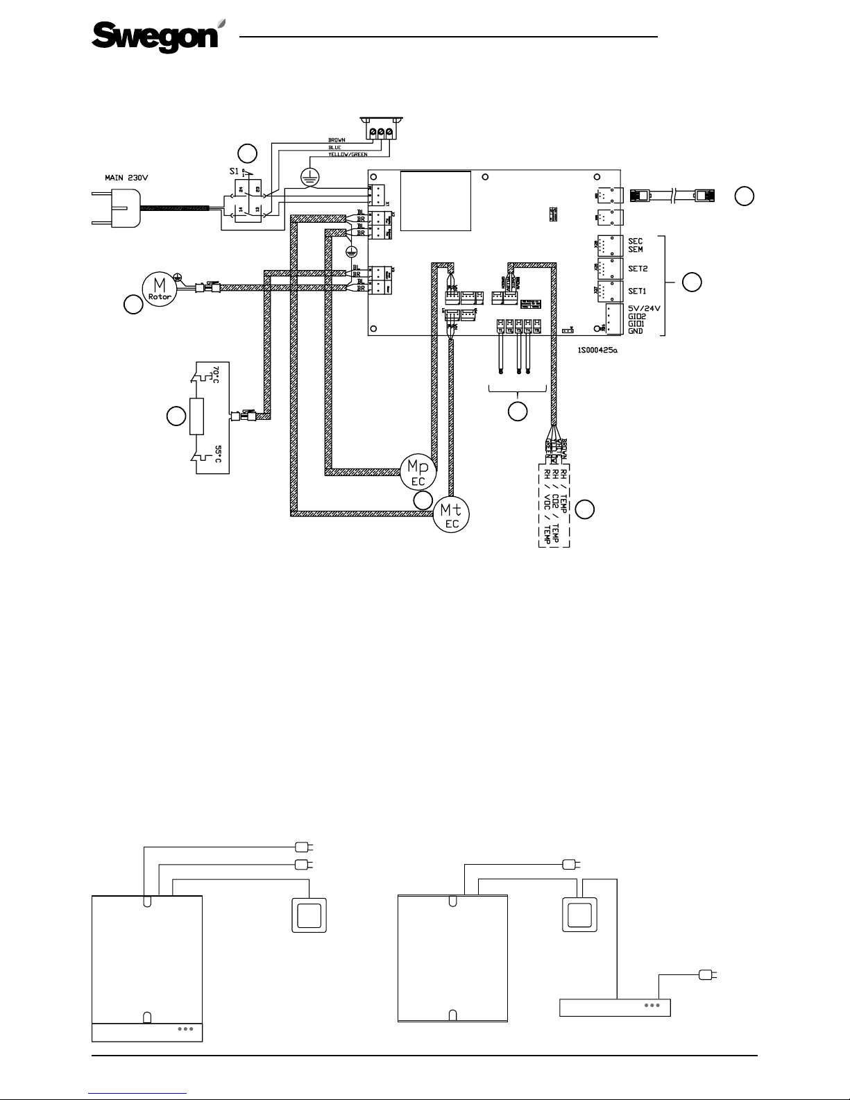
R2.060219
All rights to changes reserved.
31
www.swegon.com
8.5 Electrical wiring diagram
1. Temperature sensor:
T1 Outside air temperature
T3 Extract air temperature
T4 Supply air temperature
2. Connection for Smart control panel
3. External connections. See the section “External
connections”.
4. Service switch
5. Rotor’s motor
8.5.2 R3, CASA Jazz cooker hood and control panel
X15
X14
X12
X10
X9
T1
X29
5V/24V
1
T4T1 T3
2
UI
3
4
5
6
7
8
8.5.1 Ventilation unit
6. Reheating air heater, 500 W (option)
7. Fans
Mp extract air fan
Mt supply air fan
8. Smart sensor package
RH
RH + CO
2
(accessory)
RH + VOC (accessory)
Page 32
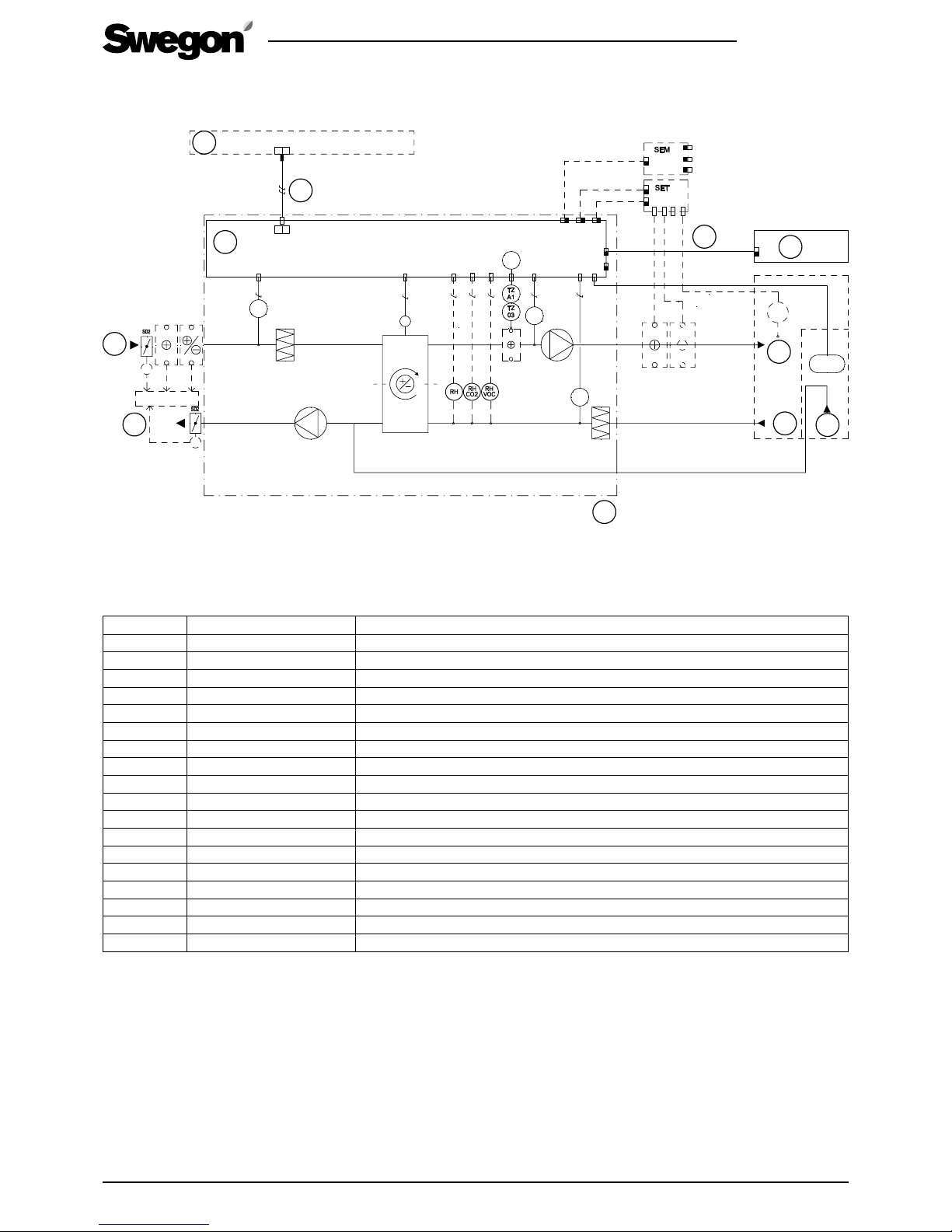
32
R2.060219
All rights to changes reserved.www.swegon.com
1: Group electrical distribution box | 2: Electrical equipment cubicle | 3: Exhaust air | 4: Outdoor air | 5: Supply: 230 V, 10 A plug-in
connection | 6: Supply demarcation of the ventilation unit | 7: Extraction from cooker hood, bypasses the heat exchanger | 8: Extract
air | 9: Supply air | 10: Modular cables with RJ9-connectors | 11: Control panel
SYMBOL DESIGNATION EXPLANATION
TC01 THERMOSTAT Reheating control/diagnostics for control
T1 TEMPERATURE SENSOR Temperature sensor, outdoor air
T3 TEMPERATURE SENSOR Temperature sensor, exhaust air
T4 TEMPERATURE SENSOR Temperature sensor, supply air
T6–T9 EXTERNAL TEMPERATURE SENSOR Connected to SET, the functions are determined through the programming of the SET unit (accessory)
TZ03 OVERHEATING PROTECTION Overheating protection, manual reset
TZA1 OVERHEATING PROTECTION Automatic overheating protection
CH COOKER HOOD SWITCH Cooker hood function
SET CONNECTION UNIT Extension module SET, Smart Extension Temperature module (accessory)
SEM CONNECTION UNIT Extension module SEM, Smart Extension Modbus module (accessory)
HR HEAT EXCHANGER Heat exchanger
SD2 DAMPERS Shut-off dampers (accessory)
SK AIR HEATER External electric air heater
HU AIR HEATER External air heater (accessory)
CU AIR COOLER External air cooler (accessory)
RH SENSOR Humidity sensor
RH + CO2 SENSOR Humidity and carbon dioxide sensor (accessory)
RH + VOC SENSOR Humidity and VOC sensor (accessory).
8.6 Control diagram
DESCRIPTION OF FUNCTIONS
CONTROL FUNCTIONS:
The ventilation unit can be controlled from a separate Smart control panel or a Smart cooker hood.
When the ventilation unit is controlled from a cooker hood, you can select Home/Away/Boost mode. You can select a damper-open period of 30, 60 or 120 minutes. The
damper inside the cooker hood will then be open for this period.
The setting value for the supply air temperature can be selected from a Smart control panel. Reheating can be shut off from the control panel.
PROTECTIVE SAFETY FUNCTIONS:
– Overheating protection for air heaters for reheating: An electric air heater is equipped with automatic overheating protection TZA1 and manual overheating protection
TZ03 (setting value 60 °C).
– The fans have automatic overheating protections.
ACTIONS IF PROTECTIVE DEVICES TRIP:
– If the manual overheating protection trips, find and rectify the fault, and then press the acknowledgement button inside the ventilation unit.
– The automatic overheating protections of the fans will reset themselves when the temperature has dropped below the setting value.
REMOTE CONTROL: Read the instructions for the ventilation unit and familiarize yourself with the Modbus parameter list.
CH
(500W)
M
T
1
HR
T
3
01
01
T6-T9
T
4
TC
01
HU
CU
M
M
SET
SK
LP/VP
I03-I05
A04
ModBus
I01-I02
1
2
3
5
6
7
8
9
10
11
4
Page 33
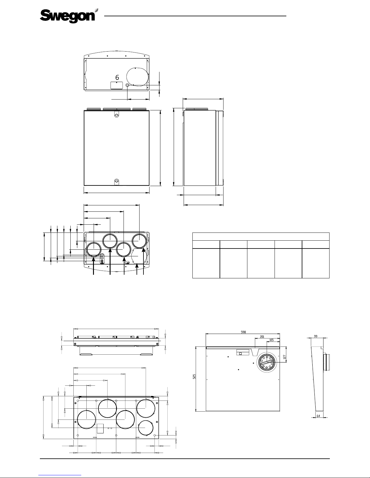
R2.060219
All rights to changes reserved.
33
www.swegon.com
Duct connections
1 2 3 4 5
Supply air
∅ 125
Extract air
∅ 125
Outdoor air
∅ 125
Exhaust air
∅ 125
Extract
air from
cooker
hood
∅ 100
599
700
719
361
369
293
45
201
91
239
364
508
79
157
207
217
235
263
1 23 45
8.7 Measurements
Swegon CASA R3
Swegon CASA Jazz cooker hood
The illustration shows the right-hand version. On the left-hand
version, the duct connection is on the left-hand side.
Ceiling mounting frame, (R-model)
302
91
239
364
508
87
166
224
33 244
25
30
130 140 140 130
30
599
34
52
6: Condensate connection
Page 34

34
R2.060219
All rights to changes reserved.www.swegon.com
8.8 Weights
• Ventilation unit R3 50 kg.
• R3 + Swegon CASA Jazz cooker hood: 57.5 kg.
8.9 Ventilation unit’s codes
• R3 Smart R, RH R03VR00S00H
R3 Smart L, RH R03VL00S00H
• R3 Smart R, 500 W, RH R03VR05S00H
R3 Smart L, 500 W, RH R03VL05S00H
8.10 Accessories for installation
• Smart control panel (SC10). Smart control panel
with Exxact frame.
• Smart humidity sensor (SRH). For Auto humidity
control.
• Smart CO2 + humidity sensor (SRHCO2). For Auto
Home/Away/Boost function and Auto humidity
control.
• Smart VOC + humidity sensor (SRHVOC). For Auto
Air Quality control and Auto humidity control.
• Smart Extension Modbus module (SEM). IOextension module with relay and Modbus RTU (in and
out connectors).
• Smart Extension Cable (SEC). IO-extension cable
with Modbus RTU (single point connector).
• Humidity switch (117KKH). For the Boost operating
mode activation.
• Fireplace function switch (102TKC). A push button
or remote Fireplace function activation.
• Presence sensor (102LT). For Boost or Away mode
activation by movement detection.
• Operation mode switch. (any potential free switch)
For Travelling, Away, Home or Boost mode activation.
• External CO2 sensor (117HDL). For Auto Home/
Away/Boost function.
• Pressure switch (117PK2). For cooker hood or
central vacuum cleaner function activation if state
signal is not available.
Air cooler for cooling the supply air
• For 160 mm ducts; SDCW 160
• For 200 mm ducts; SDCW 200
• For 250 mm ducts; SDCW 250F
Air heater for heating the supply air
• For 125 mm ducts; SDHW 125
• For 160 mm ducts; SDHW 160
Air heater in combination with ground source heat
pump
• For 200 mm ducts; SDHW 250F
Electric air heater for outdoor air duct
• For 125 mm duct; SDHE125-1T
• For 160 mm duct; SDHE160-1T
• For 200 mm duct; SDHE200-1T
Page 35
R2.060219
All rights to changes reserved.
35
www.swegon.com
Commissioning form
Function Planned air flow Default Setting
Basic air flows l/s m3/h % %
Home (supply) 50 %
Home (extract) 50 %
Away (supply) 40 %
Away (extract) 40 %
Boost (supply) 65 %
Boost (extract) 65 %
Travelling (supply) 20 %
Max Smart boost (supply) 65 %
Cooker hood function
Home state compensation (difference) 20 %
Boost state compensation correction (difference) 0 %
Hood boost (supply) 0 %
Commissioned ventilation unit serial number | User panel: Main menu/Information/Serial number.
Commissioned by: Date:
Page 36
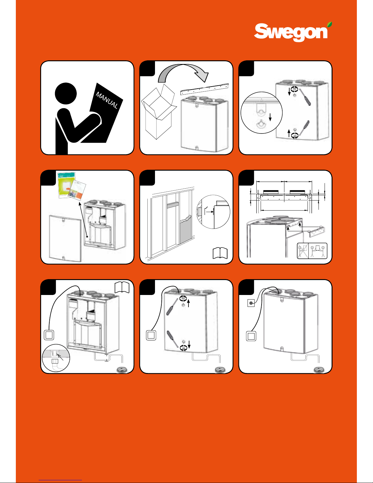
Quick Guide
1
3 5
50 kg
x
2
1
2
2
1
1
7
1
1
2
2
8
230 V
10 A
4
i
6
i
≥ 100 mm
3/8”
299 299
505
68
54
14
 Loading...