

Page 1

Swegon CASA® R120
Instructions for installation, operation and maintenance
R120_g_EN-m
Page 2
Content
Instructions for Use
For the user
Important information ����������������������������������������� 3
Control from a Premium control panel ����������������� 4
Control from a Premium cooker hood ������������������ 4
To replace the filters ��������������������������������������������� 5
Alarms ����������������������������������������������������������������� 5
Installation, operation and maintenance
R120.211112
For fitters and service personnel
1. Installation instructions ........................................ 6
Important information �����������������������������������������������������������6
1�1 General ����������������������������������������������������������������������������7
1�2 To install the ventilation unit ��������������������������������������������7
1�3 Ceiling installation �����������������������������������������������������������7
1�4 Installation in ceiling mounting frame ������������������������������8
1�5 Condensate discharge ������������������������������������������������������8
1�6 To connect the cooker hood ���������������������������������������������9
1�7 Electric and control cables ������������������������������������������������9
1�8 Ducts ����������������������������������������������������������������������������� 10
1�9 Moisture barrier against cold timber frames �������������������10
2. Operation ............................................................ 11
2�1 Basic functions ��������������������������������������������������������������� 11
2�1�1 Fans ���������������������������������������������������������������������������� 11
2�1�2 Temperature ���������������������������������������������������������������11
2�1�3 Protective functions ����������������������������������������������������11
2�2 Optional items of equipment – automated control system
��������������������������������������������������������������������������������������������11
3. Application .......................................................... 12
3�1 To set the airflows ����������������������������������������������������������12
3�2 Premium control panel ���������������������������������������������������12
3�3 Premium cooker hood ����������������������������������������������������12
3�4 Start menu ���������������������������������������������������������������������14
3�4�1 Fireplace switch function ���������������������������������������������14
3�4�2 Fan speed �������������������������������������������������������������������14
3�5 Main menu �������������������������������������������������������������������� 14
3�5�1 Language ��������������������������������������������������������������������14
3�5�2 Installation and service ������������������������������������������������ 14
3�5�3 Clock �������������������������������������������������������������������������� 14
3�5�4 Summer night cooling� ������������������������������������������������14
3�5�5 Temperature ���������������������������������������������������������������14
3�5�6 Basic display ����������������������������������������������������������������14
3�5�7 To switch off the unit ��������������������������������������������������14
3�5�8 Fireplace switch function ���������������������������������������������14
3�5�9 Weekly timer ��������������������������������������������������������������14
3�5�10 Ventilation unit model �����������������������������������������������15
3�6 Installation and service ��������������������������������������������������� 15
3�6�1 Sensor fault ����������������������������������������������������������������15
3�6�2 Service reminder/alarms ����������������������������������������������15
3�6�3 Clock �������������������������������������������������������������������������� 15
3�6�4 Temperature ���������������������������������������������������������������15
3�6�5 Measurement �������������������������������������������������������������15
3�6�6 Control �����������������������������������������������������������������������15
3�6�7 Fan speeds ������������������������������������������������������������������ 15
3�6�8 To switch off the unit ��������������������������������������������������15
3�6�9 Factory settings ����������������������������������������������������������� 15
3�6�10 Actuators ������������������������������������������������������������������ 15
3�6�11 Functions ������������������������������������������������������������������ 15
3�6�12 Electric air heater ������������������������������������������������������15
4. Servicing .............................................................. 16
4�1 Service reminder ������������������������������������������������������������16
4�2 To open the ventilation unit �������������������������������������������16
4�3 Filter change ������������������������������������������������������������������ 16
4�3 Other servicing ���������������������������������������������������������������16
5. Alarms and troubleshooting .............................. 17
5�1 Alarms ��������������������������������������������������������������������������� 17
5�1�1 Alarms from a Premium control panel �������������������������17
5�2 Troubleshooting: ������������������������������������������������������������17
5�2�1 The supply air is not sufficiently heated ����������������������� 17
6. List of components ............................................. 18
7. Technical data ...................................................... 19
7�1 Sizing �����������������������������������������������������������������������������19
7�2 Wiring diagram, ventilation unit ������������������������������������� 21
7�3 Power consumption ������������������������������������������������������� 21
7�4� Wiring diagram, optional equipment ����������������������������22
7�5 Control diagram ������������������������������������������������������������24
7�6 Dimensions �������������������������������������������������������������������� 25
7�7 Weight ��������������������������������������������������������������������������25
7�8 Optional equipment ������������������������������������������������������� 25
8. Commissioning .................................................... 26
Plant data to be given when requesting service
Project planning
See separate project planning instructions, www�swegon�com�
N.B.! The manual was originally written in Finnish.
2 www�swegon�com
Swegon reserves the right to alter specifications.
Page 3
Instructions for Use
Important information!
R120.211112
Airflows
The air in the home should be changed at a
continuous and sufficient rate to ensure a pleasant indoor climate and avoid damage to building
elements caused by dampness� The ventilation
unit should be stopped only while service work
is in progress�
The airflow from the ventilation unit can be
controlled to generate the various airflows from
a Premium control panel or a Premium cooker
hood�
• Away = a low airflow, which can be utilized
when no one is in the home and there is no
need for the same ventilation that is normally
in use, e�g� for moisture-removal�
• Home = normal airflow�
• Boost = a high airflow, used in connection
with cooking, taking a sauna bath, showering,
drying laundry and similar activities�
The Away/Home operating modes and the temperature of the supply air can be controlled with
the ventilation unit’s built-in weekly timer; however the operating mode can always be changed
from the Premium control panel or the Premium
cooker hood�
A low airflow when the home is unoccupied
means economical operation� This saves on fan
energy and the home heating system does not
have to heat as much air during the cold season�
The most important function of the ventilation system is to ensure that the indoor
air will be continuously fresh and to remove impurities and moisture from the air.
You should therefore make an appraisal of
whether a low airflow is sufficient while the
home is unoccupied. The low airflow mode
must absolutely not be used when someone
is in the home.
If the load on the home is greater than
you’ve anticipated, then you should increase
the normal airflow to a correspondingly
higher rate.
Drying laundry
A tumbler dryer of extract air type or a drying
cabinet must not be connected to the system
due to the high moisture content in the air leaving them� We recommend a condensing tumbler
dryer without duct connection�
Freeze protection
During periods of cold weather, the heat exchanger is liable to freeze if the extract air is
humid� A protective function then automatically
reduces the speed of the supply air fan� Under
such conditions, variations in the fan speed are
therefore normal�
Filters
The ventilation unit must not be operated without filters� Use only filters recommended by
Swegon in the ventilation unit�
Commissioning
The ventilation should not be commissioned until
all work that produces large quantities of grinding dust or other impurities has been completed�
Swegon reserves the right to alter specifications.
www�swegon�com 3
Page 4
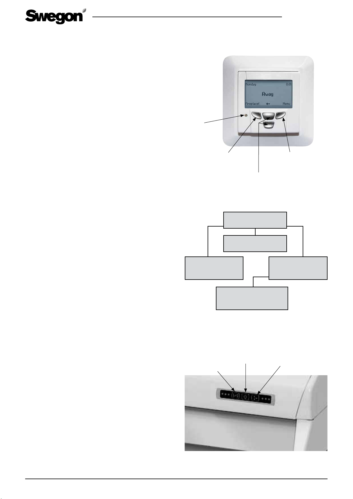
Control from a Premium control panel
When the power is switched on, the ventilation unit
starts up in the Home operating mode� The start time
is approx� 1 minute� After that, the control panel can
be used� Likewise after a power failure, the ventilation
unit starts up in the Home operating mode, if the power
failure has cleared the memory�
The functions of the push buttons are described in the
image to the right�
R120.211112
Fireplace switch function
The speed of the extract air fan decreases and the speed
of the supply air fan increases for a few minutes� This
produces excess pressure in the home and in this way
"creates" an updraught in the chimney, which makes it
easier to light the log-fire�
Selection of fan speed
The fans inside the unit can be controlled to operate at
three speeds: Home/Away/Boost� Select the required fan
speed from the control panel�
You can select an airflow boost time of 30, 60 or 120
minutes, or continuous boosted airflow�
The operating mode can be manually changed, even
when the fan speed is controlled by the weekly timer�
Menu/Installation and service
You can enter settings that affect the operation and
functions of the ventilation unit from the Installation
and service menu and submenu� You should normally
enter these settings when you install the ventilation sys-
tem� The settings are described in Sections 3�5 and 3�6�
Signal lamp
The indicating lamp on the control panel indicates the
functions and alarms of the ventilation unit with various
colours� This is described in Section 5�
Signal lamp
Fireplace switch function
Return to previous menu
level
Move to the left
Menu structure
Selection of fan speed
Move upward/downward
Entering values
Fireplace switch
function
Installation and service
(See Section 3.6)
Menu
Move to the right
Setting function
Start menu
Fan speed
Menu
(See Section 3.5)
Control from a Premium cooker hood
The ventilation unit fan speeds and other settings
should be entered via the Premium control panel� When
you have entered these settings, the functions below
will be available from the cooker hood control panel�
• The cooker hood damper� When preparing food or
carrying out a similar activity, a 30, 60 or 120 minute
damper-open period can be selected� One single
press of the button will change the setting to the
next damper-open period� The fourth press of the
button cancels the setting and closes the damper�
• The cooker hood lighting� On/Off�
• The ventilation unit fan speed� The fans inside the
unit can be controlled to operate at three speeds:
Away/Home/Boost� One single press of the button
will increase the fan speed one step� The period for
the boost speed is preset to 60 minutes, after which
the ventilation unit will return to normal airflow�
4 www�swegon�com
Control of the cooker hood shutoff damper
Indication: 30/60/120 min�
The control panel of the Premium cooker hood
Lighting Ventilation unit fan speed
Away, home, boost
Swegon reserves the right to alter specifications.
Page 5

R120.211112
To replace the filters
The home owner can change the fil-
ters himself or herself. Other service work
must be carried out by qualified service
personnel.
Extract air filter
The filter should be cleaned every six months and should
be replaced at least once per year� It may be necessary
to clean or replace the filter more often in homes where
there is considerable dust�
Supply air filter
The filter should be cleaned every six months and should
be replaced at least once per year� If the air is highly
polluted, e�g� due to heavy traffic, the filter should be
replaced more often�
Service reminder
The ventilation unit’s control system is normally preset
for displaying a service reminder every six months� This
time setting can be changed by qualified service personnel�
The locations of the filters in a ventilation unit in
the right-hand version.
The locations of the filters are mirror-inverted in a
ventilation unit in the left-hand version.
Wide-meshed filters
and fine filter
Fine filter
Alarms
Alarms from a Premium control panel
• The indicating lamp is flashing red: The automated
protection system has stopped the fans due to a
malfunction� The alarm text is shown in the display�
Contact service!
• The indicating lamp is lit with a steady red glow:
Alarm or a service reminder� The alarm text is shown
in the display� Contact service!
• The indicating lamp indicates certain unit functions
with other colours� See Section ”3�2 Premium control
panel”
The ventilation unit must not be op-
erated without filters!
Use only filters recommended by Swegon
in the ventilation unit.
Find the correct filters in Section 6.
List of components
.
Swegon reserves the right to alter specifications.
www�swegon�com 5
Page 6

1. Installation instructions
Important information!
R120.211112
Qualified personnel only
The installation work, the entering of settings
and commissioning should be carried out by
qualified personnel only�
Standards and requirements
The pertinent national standards and regulations dealing with installation, the entering of
settings and commissioning must be followed if
the equipment is to operate correctly�
You will find the document entitled “Project
design instructions for ventilation” at the web
address www�swegon�com/casa, in which
requirements on electric power, noise, airflows
and duct systems are presented� Each country
has specific national requirements which must
be observed�
Right-hand or left-hand version
Check whether the ventilation unit has been
supplied in the right-hand or left-hand version
to make certain that you are connecting the air
ducts to the correct duct connection spigots on
the unit� See also the dimensional drawings in
Section 7, Technical data�
Drying laundry
A tumbler dryer of extract air type or a drying
cabinet must not be connected to the system
due to the high moisture content in the air leaving them� We recommend a condensing tumbler dryer without duct connection�
The covered duct connection spigots
The duct connection spigots of the ventilation
unit must be covered by lids during transport,
storage and installation�
Filters
The ventilation unit must not be operated
without filters� Use only filters recommended by
Swegon in the ventilation unit�
Commissioning
The ventilation should not be commissioned
until all work that produces large quantities
of grinding dust or other impurities has been
completed�
6 www�swegon�com
Swegon reserves the right to alter specifications.
Page 7

1.1 General
You can install the ventilation unit in a scullery, storage space, attic, etc� If the ventilation unit is located
in a cold space, it should be have thermal insulation, if
required�
The ventilation unit conforms to enclosure class IP 44
when the cover is closed�
Connect the extract air from the Premium cooker hood,
if the need arises, via a duct to the extra duct connection spigot on the top side of the ventilation unit�
Otherwise, blank off the connection spigot�
To make it easier to lift the ventilation unit, the inspection cover can be removed and the heat exchanger
can be dismantled from the unit� The fans can also be
removed if necessary� See Section 4, Service�
1.2 To install the ventilation unit
Secure the ventilation unit to the wall using the wall
mounting bracket supplied with the unit�
R120.211112
Horizontal stud for the ventilation unit’s mounting bracket
Acoustic insulation
On delivery, the package containing
the wall mounting bracket is inside the
bypass duct.
The ventilation unit should not be secured to a
wall that borders to a living room or a bedroom.
If the wall is composed of vertical studs and building
boards, the wall must be reinforced with horizontal
studs to enable it to support the weight of the unit�
Swegon also recommends that the wall be insulated
with mineral wool or similar insulation for preventing
sound from propagating to other rooms�
Secure the mounting bracket horizontally to the wall
with screws, using a suitable means of anchoring that
can support the weight of the ventilation unit�
Lift the ventilation unit into place, so that the wall
bracket tips engage into the corresponding slots on the
backside of the ventilation unit�
Make sure that the electric and control cables are
visible. See also Section 1.7 Electric and control
cables.
Wall mounting bracket’s dimensions
Horizontal reinforcement
Wall mounting bracketInsulated wall
The ventilation unit can also be mounted in a mounting
frame on the ceiling� See Optional Equipment�
1.3 Ceiling installation
Fasten the ceiling mounting frame with four M8 threaded rods in the ceiling anchor sleeves so that at least
three of the threaded rods are aligned with the corners
of the ceiling mounting frame� To avoid a possible collision with the ducts, one of the threaded rods can be
located in the hole next to the corner� Screw in the M8
nuts onto the threaded rods to such a height that the
Swegon reserves the right to alter specifications.
The points on the locking hooks on
the edge of the ceiling mounting frame
should be bent back.
The bottom of the ceiling mounting frame
should be positioned approx. 15 mm below the ceiling surface. If ceiling moulding
is fitted around the frame, it should be
mounted after the unit has been installed.
www�swegon�com 7
Page 8
R120.211112
ceiling mounting frame will be horizontal when the top
of the frame goes against the nuts� Fit the mounting
frame through the selected holes against the nuts on
the threaded rods and lock the frame into position with
nuts from below� The ends of the threaded rods are permitted to stick out max� 3 cm from the ceiling mounting
plate� If they stick out farther, they will protrude against
the unit’s upper casing section�
1.4 Installation in ceiling mounting frame
Run the power supply and data cable through the ceiling mounting frame before you lift the unit into position� Lift the ventilation unit into the ceiling mounting
frame so that all four locking hooks will fit correctly in
the notches at the top of the unit� The locking hooks
have two catches; the lower one locks the unit to
facilitate connection to the ducts and the wiring of the
electric cables� When the unit is at the correct position
in relation to the duct and the electric cables have been
run inside the unit, lift up the upper catches� When
the catches are locked the screws of the upper section
spring out� Finish by ensuring that the ventilation unit is
mounted at its location by tightening the screws in the
upper casing section�
Make sure that no wires
or the like come to rest
between the ventilation
unit and the mounting
bracket.
The R120 lifted up on
the lower catches.
Lock the R120 into
place by tightening
the screws in the front.
1.5 Condensate discharge
As a rule, no condensate discharge is needed under dry
ambient conditions and in combination with a rotary
heat exchanger� A certain amount of humidity load is
common in homes� If substantial moisture is produced
in the home, connect the ventilation unit’s condensate
drain connection to discharge piping�
Connect the condensate discharge hose to the condensate discharge connection of the unit (3/8”, Male
threads)� The condensate must be channelled to a floor
gulley, the water trap of a sink or the equivalent by
means of a stiff hose or a pipe having an inner diameter
of at least 12 mm� The water must not be led away
directly to the sewer�
Vertically mount the water trap on the hose supplied
with the unit and fill it with water� The hose must not
have a second water trap or be run horizontally� The
damming height of the water trap should be at least
100 mm�
Do not use the cooker hood for basic
kitchen ventilation; use it only when you
prepare food.
Condensate discharge
Ø 125 mm
The electric and control cables of the
ventilation unit are located on the top side
of the unit. Make sure that the electric cable can be connected to a wall outlet.
8 www�swegon�com
Swegon reserves the right to alter specifications.
Page 9

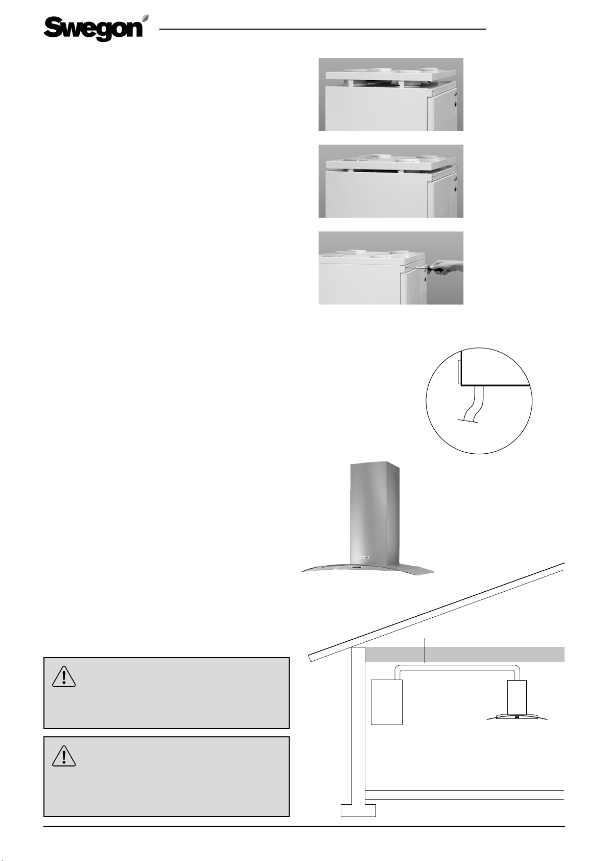
1.6 To connect the cooker hood
Connect a duct from the cooker hood duct connection spigot to the connection spigot on the top side
of the ventilation unit, which is intended for separate
extract air and which conveys the air to bypass the heat
exchanger�
The duct between the cooker hood and the ventilation
unit must be mounted in such a way that makes it possible to clean it�
R120.211112
If the bypass from the kitchen is not used, the outlet
spigot must be blanked off�
1.7 Electric and control cables
The unit has an earthed plug contact for connection to
the mains power� The mains plug serves as the ventilation unit’s main switch and it should be connected to an
electric socket at an easily accessible spot�
The room unit is equipped a 1�5 m long cable with plugin contact, installed from the topside of the ventilation
unit� Arrange the wall outlet at an easy-to-reach location� For power requirement particulars, see Section 7,
Technical data�
Connect the ventilation unit to the Premium control
panel via a modular cable� Install the Premium control
panel at a place of your choice� Two modular cables are
included in the supply: one approx� 3 m long cable and
one 20 m long cable�
When installing the unit, make sure that you provide
adequate access to the connector of each cable (loose
ones as well), e�g� for servicing and adjusting the unit, if
and when the need arises�
The diameter of the modular cable wiring tube should
be 20 mm�
To dismantle the front plate on a Premium control panel.
To connect the modular cable. The extra contact is used for
connection of an extra control panel.
The electric and control cables are
located on the top side of the ventilation
unit. Make sure that the electric cable can
be connected to a wall outlet without obstruction.
The connection of possible optional equipment is
described in the wiring diagram in Section 7, Technical
data� The cables for the optional items of equipment are
not included in the supply�
If you lengthen the modular cable
within some building element (e.g. in a
wall), you should lengthen the cable in a
20 mm dia. conduit, anticipating a possible
later change of cabling.
Swegon reserves the right to alter specifications.
www�swegon�com 9
Page 10
R120.211112
1.8 Ducts
Install the air ducts, sound attenuators, supply air diffusers, air intake grilles and exhaust air ducts as shown in
the ventilation drawings� To prevent the propagation of
sound, do not install the ducts directly against structural
building elements�
Insulate the air ducts in order to reduce loss of heat or
cooling energy and to prevent water from condensing
on surfaces�
In general, ventilation ducts are insulated in the following manner:
• Outdoor air ducts are insulated in warm spaces and
in attics that are used�
• Exhaust air ducts should always be insulated in accordance with national regulations� See separate project planning instructions (for example Fire resistance
classification requirements)�
• Insulate supply air ducts in cold spaces�
• Insulate extract air ducts in cold spaces�
• If the air inside the duct is colder than the air in the
surroundings, the insulation should be protected by
a moisture barrier (e�g� outdoor air and exhaust air in
interior spaces, or chilled supply air)�
1.9 Moisture barrier against cold timber
frames
It is important that the moisture barrier between cold
stud work and the warm ceiling maintains its tightness
at duct penetration points� A duct penetration piece
(optional extra) will facilitate this�
The thickness of the insulation and
the nature of the surface layer of the ventilation ducts vary depending on insulation
material, climate zone and national standards in force. For this reason, Swegon does
not offer any general recommendations.
Most manufacturers of insulation material
offer calculation programs for the calculation of sufficient and correct insulation.
In renovation projects, it is advisable to
examine the existing ducts to determine
whether they are sufficiently and correctly
insulated.
It is essential that the ventilation
ducts are clean in order for the ventilation
unit to operate as it should. The ventilation ducts should be cleaned regularly
and always when the home is renovated.
10 www�swegon�com
Insulating in the right way is necessary for
the ventilation unit to operate correctly.
When the freeze protection function
is activated, you cannot change the ventilation unit fan speeds from the control
panel.
Swegon reserves the right to alter specifications.
Page 11

R120.211112
This item is available in sets of 5 for size 100, 125 and
160 mm dia� ducts� It can be fastened with tape in the
moisture barrier�
We recommend the use of a mounting frame (optional
extra) for sealing the moisture barrier in the attic tie
beams�
Cut up the openings with approx� 10 mm smaller
diameter than that of the ducts� Secure the mounting
frame in the ceiling with screws through the holes on
the sides� The plastic film of the moisture barrier should
either be stretched and fastened between the mounting
frame and the structural element of the building, or be
taped tightly against the mounting frame�
2. Operation
2.1 Basic functions
How to activate and set the functions is described in
Section 3, Application.
2.1.1 Fans
The fans can be controlled to different operation modes
from a control panel or a Premium cooker hood�
• Away = a low airflow, which can be utilized when no
one is in the home and there is no need for the same
ventilation that is normally in use, e�g� for moistureremoval�
• Home = normal airflow�
• Boost = a high airflow, used in connection with cook-
ing, taking a sauna bath, drying laundry and similar
activities�
The Away/Home operating modes are controllable with
the ventilation unit’s built-in weekly timer; however the
operating mode can always be changed from a Premium control panel (or from the control panel on a cooker
hood�
The airflow boost time can be selected manually to 30,
60 or 120 minutes, or for continuous boosted airflow,
from a Premium control panel� When the unit is controlled from a Premium cooker hood, the fan’s boost
time is 60 minutes and the time that the damper is open
can be selected to 30, 60 or 120 minutes�
2.1.2 Temperature
The user sets the desired temperature, and the ventilation unit then strives to reach this temperature if
possible� In general, the user should set a temperature
between 13 and 20 °C� The temperature should be
lower than the room temperature, so that the supply air
will thoroughly mix with the room air� Note that a high
temperature setting will increase the ventilation unit’s
consumption of electric power� The factory-preset supply air temperature is 17 °C�
When the heat exchanger’s heating capacity is insufficient for reaching the preset supply air temperature, the
speed of the supply air fan will decrease and the supply
air temperature will rise� The fan will stop if the supply
air temperature drops despite this measure�
If there is an electric air heater inside the ventilation
unit, it will be activated when the heat exchanger’s
heating power is insufficient, and the air heater will
strive to reach the supply air temperature setting� If no
heating is required, the air heater can be switched off
from a Premium control panel�
The function for summer night cooling can be used
for utilising the cool night air to cool down the home�
The automatic function for summer night cooling stops
the rotary heat exchanger when heat recovery is not
needed� The heat exchanger starts up and makes use of
the extract air if the indoor air is cooler than the outdoor air� The limit values of the function are adjustable
from a Premium control panel�
2.1.3 Protective functions
The electric air heater has two protective functions�
One automatic excess temperature cutout switches off
the air heater if a fault situation arises� This protective
function automatically resets itself when the air heater
has cooled down�
The excess temperature cutout with manual reset can
be reset by pressing a button inside the ventilation unit�
The location of the button is marked in the adjacent
illustration� The excess temperature cutout is reset when
you sense a click on pressing the button�
The heat exchanger is equipped with a freeze protection� The speed of the supply air fan decreases when
cold weather involves risk that the heat exchanger will
freeze� If the supply air temperature drops further, the
controller switches off the supply air fan� This protective
function automatically resets itself when the temperature rises�
The fans have a thermal overload cutout, which stops
them if the temperature rises too high� The controller
also stops the fans if a serious malfunction occurs in the
ventilation unit� The protective function resets itself automatically when the temperature drops or the malfunction has been remedied�
2.2 Optional equipment – automated
control equipment
How to activate and set the functions is described in
Section 3, Application. The connection of optional
equipment is described in the wiring diagram in Section
7, Technical data.
The optional items of equipment can be used
for achieving the type of control required in the following way:
• Boost timer. The boosted operation mode can be
switched in from a control panel or a Premium cooker
hood� A separate boost timer (push button) can be
installed in another place, e� g� in a sauna, bathroom,
scullery, etc�
• Humidity sensor. Detects whether a preset limit
Swegon reserves the right to alter specifications.
www�swegon�com 11
Page 12

R120.211112
value, e�g� 60 % relative humidity (RH), is exceeded
and switches the fan to operate in the boosted flow
mode� It can be placed in a sauna, a bathroom, a
scullery, etc� The sensor voltage is 24 V DC�
• Separate fireplace switch. The function can be
switched in from a control panel or a Premium cooker
hood� A separate fireplace switch (push button) can
be installed in another place, e� g� next to an open
fireplace� The speed of the extract air fan decreases
and the speed of the supply air fan increases for a
few minutes� This produces excess pressure in the
home and in this way "creates" an updraught in the
chimney, which prevents smoke from entering the
room when you light the log-fire�
• Occupant detection sensor. The sensor detects
movement in the home and increases the fan speed
to the Home value�
• Carbon dioxide sensor. It is suitable for use when-
ever the number of occupants varies� The sensor
increases the fan speed to the Boost value, when a
preset maximal value is exceeded, e�g� 900 ppm�
• Negative pressure compensation. Negative pres-
sure arises in the home when a separate cooker hood
or central vacuum cleaner is used, since the extract
airflow becomes substantially higher than the supply
airflow� A separate sensor (e�g� one that senses the
difference in pressure) can transmit a signal to the
controller to increase the supply air flow from the
ventilation unit to restore balance�
• Supervision (DDC). Certain functions can be con-
trolled from the automated building management
system of the building� See the connection schedule
for optional items of equipment in Section 7, Technical data�
• Home/Away switch.
from a cooker hood, generally have a separate Home/
Away switch (optional extra) by the front door� The
switch starts the Away function in the ventilation unit�
The switch can be a standard switch of optional type�
See Section 7�
For example, systems controlled
3. Application
3.1 To set the airflows
The home should have continuous air change to ensure
a pleasant indoor climate and avoid damage to building
elements due to humidity� The ventilation unit should be
stopped only while service work is in progress�
The airflows should be set according to the ventilation
plan and applicable regulations� For estimated values,
use the sizing curves in Section 7, Technical data� A
qualified person should set the ventilation unit’s and the
ventilation equipment’s airflows using appropriate measurement equipment�
A low airflow when the home is unoccupied means
economical operation� This saves on fan energy and the
home heating system does not have to heat as much
air during the cold season� An assessment of whether a
low airflow is sufficient for removing emissions, moisture, etc� from the air should be made�
3.2 Premium control panel
When the power is switched on, the ventilation unit
starts up in the Home operating mode� The start time
is approx� 1 minute� After that, the control panel can
be used� Likewise after a power failure, the ventilation
unit starts up in the Home operating mode, if the power
failure has cleared the memory�
The functions of the push buttons are described in the
image�
The indicating lamp on the control panel shows the various functions of the ventilation unit in different colours�
1� Steady green glow: The ventilation unit is operating
normally�
2� Flashing green glow: The freeze protection has been
activated�
3� Orange flashing glow: The electric air heater has been
activated� (Reheating is optional equipment�)
12 www�swegon�com
4� Flashing red glow: The automated protection system
has stopped the fans due to a malfunction�
5� Steady red glow: Alarm or a service reminder�
3.3 Premium cooker hood
The ventilation unit fan speeds and other settings
should be entered via the Premium control panel� When
you have entered these settings, the functions below
will be available from the cooker hood control panel�
• The ventilation unit fan speed� The fans inside the
unit can be controlled to operate at three speeds:
Away/Home/Boost� One single press of the button
will increase the fan speed one step� The period for
the boost speed is preset to 60 minutes, after which
the ventilation unit will return to normal airflow�
• The cooker hood damper� When preparing food or
carrying out a similar activity, a 30, 60 or 120 minute
damper-open period can be selected� One single
Swegon reserves the right to alter specifications.
Page 13

R120.211112
press of the button will change the setting to the
next damper-open period�
• The cooker hood lighting� On/Off�
Before commissioning the ventilation
system, check that the ventilation unit, filters and ducts are clean and that there are
no loose objects inside them.
Premium control panel
Signal lamp
Fireplace switch function
Return to previous menu
level
Move to the left
Selection of fan speed
Move upward/downward
Entering values
Menu
Move to the right
Setting function
Control panel, Premium cooker hood
Control of the cooker hood shutoff damper
Indication: 30/60/120 min�
Lighting Ventilation unit fan speed
Away, home, boost
Swegon reserves the right to alter specifications.
www�swegon�com 13
Page 14

R120.211112
3.4 Start menu
3.4.1 Fireplace switch function
The fireplace switch function decreases the extract air
fan speed and increases the supply air fan speed for
approx� 10 minutes� This produces excess pressure in
the home and in this way "creates" an updraught in the
chimney, which prevents smoke from entering the room
when you light the log-fire�
An unnecessary or longterm use of the fireplace switch
function in the wintertime may easily activate the frost
protection function during an unnecessarily long time,
which creates negative pressure in the house and smoke
can be drawn into the house via the chimney� You can
cancel the fireplace switch function by pressing the
fireplace switch function button once again within 10
minutes after you pressed it the first time�
N.B.! The ventilation unit is no source for necessary replacement air while a fire is burning in the
fireplace.
The function is shown in the display only if the value is
On in Menu 3.5.8.
3.4.2 Fan speed
Select the appropriate fan speed� Timer-controlled
airflow boost is available� The operating mode can be
manually changed, even when the fan speed is controlled by the weekly timer�
Menu structure
3.4.1
Fireplace switch
function
3.6 Installation
and service
See next page!
3.4 Start menu
3.4.2 Fan speed
• Away
• Home
• Boost
3.5 Main menu
• Language
• Installation and service
Time switch clock
(timer)
Summer night
cooling
Temperature
Base display
Fireplace switch
function
Switch off
3.5 Main menu
You can enter settings that affect the operation and
functions of the ventilation unit from the menu�
N.B.! A number of functions are available in the
Main menu as well as in the Installation and Service submenu.
From the Montage and service menu, you select whether the function should be used and certain settings�
The function must be activated from the main menu�
3.5.1 Language
Select the appropriate language�
3.5.2 Installation and service
See Section 3�6, Installation and service�
3.5.3 Clock
Select date and time of day�
3.5.4 Summer night cooling.
This function utilises the cool night air to cool down the
home� The rotary heat exchanger stops�
Conditions for start:
• The reheating function is not active�
• The extract air temperature is above 22 °C� The
outdoor temperature is above 16 °C, but at least 1
°C lower than the extract air temperature� It is possible to change the temperature limits and select fan
speeds�
Weekly timer
Unit model
3.5.5 Temperature
Set the desired supply air temperature (factory setting:
17 °C)� The ventilation unit’s heat exchanger and an air
heater, if included, are automatically activated so that
the desired temperature will be reached� The supply air
temperature should be lower than the room temperature,
so that the supply air will thoroughly mix with the room
air� Note that a high temperature setting will increase the
ventilation unit’s consumption of electric power�
3.5.6 Basic display
Basic display 1 is selected when the fan speeds in the
Away/Home/Boost steps are to be changed�
Basic display 2 is selected when the fan speeds are to be
changed in five different steps�
3.5.7 To switch off the unit
The ventilation unit fans, the heat exchanger and an air
heater, if fitted, are stopped� The circuit card is however still energised and the settings are preserved in the
memory�
3.5.8 Fireplace switch function
Select ON as the value for this function, if you wish to
use the function from the control panel display, otherwise select Off� See also 3�4�1 above�
3.5.9 Weekly timer
Four different programs can be selected on the weekly
14 www�swegon�com
Swegon reserves the right to alter specifications.
Page 15

R120.211112
timer, with the Away–Home–Boost fan speeds� Manual
operation from the control panel bypasses (overrides)
the weekly timer functions�
3.5.10 Ventilation unit model
Shows the model of the ventilation unit�
3.6 Installation and service
The menu is can be opened by entering code 1234�
3.6.1 Sensor fault
Contact a service company�
3.6.2 Alarms/Service reminder
The service reminder appears on the screen at six-month
intervals� On completed service, the reminder is set to
zero from the menu and a new period of six months
begins� The time period can be altered from the Functions menu�
Alarms for malfunctions are displayed in the display�
3.6.3 Clock
”On” or ”Off”�
The clock is displayed in the start menu�
3.6.4 Temperature
”On” or ”Off”�
The supply air temperature control function is displayed
in the start menu� Select ON in order to use the function
for setting the supply air temperature, otherwise select
Off� (The models with reheat�)
3.6.5 Measurements
Depending on the accessories connected, the following can be measured: the carbon dioxide content (CO
temperature, pressure differential, the speed of the fans
and relative humidity (RH)�
3.6.6 Control functions
Carbon dioxide content (CO
), supervision (DDC) or
2
timer can be selected as a control means�
3.6.7 Fan speeds
N.B.! The Summer night cooling function should be
deactivated whenever you change the fan speeds.
One of five fan modes (1–5) can be selected for each
operating mode (Away, Home, Boost etc�)�
The various fan mode speeds (expressed as a percentage: 10–100) can then be selected (separate for supply
air and extract air)�
3.6.8 To switch off the unit
The ventilation unit fans, the heat exchanger and an air
heater, if fitted, are stopped� The circuit card is however still energised and the settings are preserved in the
memory�
),
2
3.6 Installation and service
(code 1234)
• Alarm/Service reminder
• Time switch clock (timer)
• Temperature
• Measurements
• Control functions
• Fan speeds
• Switch off
• Factory settings
• Controller
• Functions
• Air heater
3.6.9 Factory settings
All settings except the fan speeds are reset to factory
values�
3.6.10 Actuators
It is possible to select settings for duct equipment, the
valve actuators or circulation air regulation�
3.6.11 Functions
• Select ON as the value for Low pressure compensation, e�g� if the cooker hood has a differential pressure guard in the extract air duct of the cooker hood
for this function, otherwise select OFF�
• Select ON as the value for Service reminder, if the
function is to be used, otherwise select Off� The time
interval (6 months) can be changed�
• Select ON as the value for Summer night cooling, if
you wish to select the function in the menu, otherwise select Off�
• Select On as the value for Heating, if an air heater
is installed, otherwise select Off� The limit value for
high temperature is 50 °C� The temperature can be
changed� Supply air fan ctrl is selected as the control
means, this can be changed to Room controlled�
• Select On as the Fireplace switch function setting,
if a fireplace switch has been installed, otherwise
select Off� The fireplace switch function decreases the
extract air fan speed and increases the supply air fan
speed� The freeze protection works in the reverse
manner: It stops the supply air fan and only allows
the extract air fan to run�
• Select On as the value for Boost, if a boost timer or a
presence detector is installed, otherwise select Off�
3.6.12 Electric air heater
If the ventilation unit has an air heater for reheating,
select the ”In operation” setting� The air heater is not
activated when the outdoor air temperature is above 11
°C� The temperature limit can be changed�
Swegon reserves the right to alter specifications.
www�swegon�com 15
Page 16

4. Servicing
4.1 Service reminder
The ventilation unit’s control system is normally preset
for displaying a service reminder every six months� If
required, this function can be altered in the Installation
and Service menu� From same menu you set to zero the
service reminder after performed service�
4.2 To open the ventilation unit
Isolate the power supply voltage to the ventilation unit
(pull out the mains plug from the wall socket)� Wait a
few minutes before you open the inspection covers on
the ventilation unit, so that the fans will have time to
stop and the air heaters can cool down�
4.3 Filter change
• To open the front inspection cover�
• Wait a few minutes, so that the fans have time to
stop and the air heaters, if fitted, have time to cool
down�
• Change the filters�
• Close the inspection cover�
The filters should be vacuum cleaned every six
months and should be replaced at least once per
year.
R120.211112
The ventilation unit must not be op-
erated without filters!
Use only filters recommended by Swegon
in the ventilation unit.
Find the correct filters in Section 6. List of
components.
The locations of the filters in a ventilation unit in
the right-hand version.
The locations of the filters are mirror-inverted in a
left-hand model.
Wide-meshed filters and fine filter
4.3 Other servicing
To be carried out at least once per year.
• Withdraw the heat exchanger for inspection� If you
withdraw the entire heat exchanger, you must also
disconnect the quick-fit connector� Then remove the
front panel�
Check that the drive belt is not worn� Replace it if it
is worn�
Check that the heat exchanger passages are not
clogged� Clean with a soft brush, vacuum cleaner or
under running water, if needed� If you find it necessary to use detergent, choose one that does not
corrode aluminium� Protect the heat exchanger drive
motor to prevent contact with liquid�
N.B.! The passages of the heat exchanger should
be dry before you refit it.
• Clean the inner surfaces of the ventilation unit, if
needed�
• Check that the condensate discharge outlet is not
clogged and check its outflow by pouring water on
the bottom of the ventilation unit�
Fine filter
16 www�swegon�com
Swegon reserves the right to alter specifications.
Page 17

R120.211112
5. Alarms and troubleshooting
5.1 Alarms
5.1.1 Alarms from a Premium control panel
• The indicating lamp is flashing red: The automated
protection system has stopped the fans due to a
malfunction� The alarm text is shown in the display�
Remedy the malfunction�
• The indicating lamp is lit with a steady red glow:
Alarm or a service reminder� The alarm text is shown
in the display� Remedy the malfunction or perform
service on the ventilation unit�
• The indicating lamp indicates certain unit functions
with other colours� See Section ”3�2 Premium control
panel”
5.2 Troubleshooting:
Eventual malfunctions are shown by alarm texts in accordance with 5�1�1� Investigate the components related
to the malfunction and remedy the malfunction�
5.2.1 The supply air is not sufficiently heated
Low temperature setting for the supply air
Investigate and, if needed, increase the temperature
from the menu�
The electric air heater is faulty (optional equipment)
The air heater has one excess temperature and one
overheating protection functions� The alarm is initiated
in accordance with Section 5�1�1� if either of these are
activated�
the command with the highest priority, e�g� the freeze
protection�
Priority 1: Commands from outer sensor or the ventilation unit’s protective functions�
Priority 2: External supervision (DDC)�
Priority 3: A normal control panel or the operation of
the cooker hood�
Freeze protection
During periods of cold weather, the heat
exchanger is liable to freeze if the extract
air is humid. A protective function then
automatically reduces the speed of the
supply air fan. Under such conditions,
variations in the fan speed are therefore
normal.
The LED on a Premium control panel
flashes green when the freeze protection
is activated.
The over temperature protection resets itself automatically when the temperature decreases� The overheating
protection must be reset by pressing a push button on
the air heater� If you hear a click when you press in the
button, this indicates that the overheating protection
has been reset�
Excessively high temperature may be due to too low an
air flow through the air heater� The cause can be that
a filter, outer wall grille or supply air device is clogged�
Replace and clean, if needed�
Tip: In most models, the outer wall grill has an insekt
net� If the net has small mesh, dust and insects can clog
it� During certain conditions it it is also liable to freeze�
Remove the net or replace it with a net with larger
mesh�
An excessively high temperature can also be due to the
supply air fan having stopped or that the temperature
sensor has been shaken loose from its position in the
fan intake�
Badly isolated ventilation ducts
If the unit emits warm air but the supply air discharged
from the air diffuser feels cold, this may be due to
poorly insulated ventilation duct�
The ventilation unit does not obey commands
If two overlapping commands are issued, the unit obeys
Swegon reserves the right to alter specifications.
www�swegon�com 17
Page 18

6. List of components
R120.211112
Position Component Data Order no.
1 Circuit card 603012
2 Reheating cassette 10212RVM
3 Fan motor G3G146-ED23-06 119 W (R) 60842
3 Fan motor G3G146-ED23-56 119 W (L) 60844
4 Heat exchanger (complete) 61052
5 Modular cable, 20 m PMK20
6 Premium control panel PSP148
7 Temperature sensors
8/9 Set of filters 2 class F7 fine filters
1 class G3 wide-mesh filter
10 Front access panel DR120RL
10212RSS
18 www�swegon�com
Swegon reserves the right to alter specifications.
Page 19

0
50
100
150
200
250
300
350
400
450
500
020406080100 120140
100%
87%
81%
76%
71%
67%
63%
60%
57%
54%
50%
46%
7. Technical data
0
50
100
150
200
250
300
020406080 100 120 140
100%
87%
81%
76%
71%
67%
63%
60%
57%
54%
50%
46%
7.1 Sizing
R120.211112
Supply air
500
100 %
450
400
87 %
350
81 %
300
76 %
250
71 %
67 %
200
63 %
60 %
150
57 %
54 %
Available pressure, Pa
100
50 %
46 %
50
0
0 20 40 60 80 100 120 140
Airflow, l/s
Extract air
Power consumption
Total power consumption, W
Airflow, l/s
Available pressure, Pa
Airflow, l/s
Thick line = SFP 2.0 or lower.
Acoustical performance
Sound emitted to supply air duct
Fan setting
%
54 67 60 55 50 48 42 36 22 54
57 67 63 57 52 51 45 39 27 56
60 67 63 58 53 52 46 41 29 57
63 67 65 60 54 53 48 43 32 58
67 71 66 61 56 55 50 45 35 60
71 72 68 62 57 56 52 46 36 61
76 74 70 64 59 57 54 48 38 63
81 75 71 65 59 57 54 48 40 64
87 77 73 67 61 59 56 50 42 65
100 78 75 69 63 60 58 52 44 67
Swegon reserves the right to alter specifications.
Sound power level broken down into octave bands, L
63
Hz
125
Hz
250
Hz
, dB
wokt
500Hz1000Hz2000Hz4000Hz8000
Hz
Weighted sound
power level,
, dB(A)
L
WA
www�swegon�com 19
Page 20

Sound emitted to extract air duct
R120.211112
Fan setting
%
Sound power level broken down into octave bands, L
63
Hz
125
Hz
250
Hz
500Hz1000Hz2000Hz4000Hz8000
wokt
, dB
Hz
54 64 46 48 43 37 33 23 8 45
57 64 48 49 45 38 34 24 9 46
60 62 58 51 46 39 35 26 11 49
63 64 61 51 48 40 36 27 13 50
67 63 63 53 49 41 38 29 15 52
71 63 63 55 50 43 40 31 17 53
76 66 66 56 52 44 41 32 19 55
81 63 66 57 54 45 42 33 20 55
87 66 68 58 55 46 43 35 22 57
100 66 68 59 55 46 43 35 22 57
Sound emitted to extract air duct of the cooker hood
Fan setting
Sound power level broken down into octave bands, L
%
63
Hz
125
Hz
250
Hz
500Hz1000Hz2000Hz4000Hz8000
54 63 - 49 44 33 31 25 13 45
57 65 - 51 45 34 32 27 15 47
60 63 53 53 46 35 33 28 17 48
63 59 47 53 47 37 35 30 18 48
67 61 59 55 48 37 36 31 20 50
71 64 57 56 49 39 37 32 22 51
76 69 59 57 51 40 39 34 24 53
81 68 61 59 52 41 40 36 26 54
87 66 64 60 52 43 41 37 27 55
100 67 65 61 53 43 42 38 29 56
wokt
, dB
Hz
Weighted sound
power level,
, dB(A)
L
WA
Weighted sound
power level,
, dB(A)
L
WA
Sound emitted to the surroundings
Fan setting
Sound power level broken down into octave bands, L
%
63
Hz
125
Hz
250
Hz
500Hz1000Hz2000Hz4000Hz8000
54 44 46 37 28 23 12 - - 30
57 46 46 38 29 24 13 - - 35
60 46 46 39 30 25 14 - - 35
63 44 47 40 30 26 14 - - 36
67 45 47 42 33 28 17 - - 37
71 44 48 43 34 29 19 10 - 38
76 46 49 44 34 29 20 11 - 39
81 47 50 45 36 32 21 12 - 40
87 49 52 46 37 33 22 14 - 42
100 51 54 48 39 34 24 15 - 43
20 www�swegon�com
wokt
, dB
Hz
Weighted sound
power level,
, dB(A)
L
WA
Swegon reserves the right to alter specifications.
Page 21

R120.211112
7.2 Wiring diagram, ventilation unit
The ventilation unit conforms to enclosure class IP 44�
Excess temperature sensor
Exhaust air sensor
Extract air sensor
Suppy air/frost protection sensor
Control panel
Room air sensor
Supply air sensor
Outdoor air sensor
7.3 Power consumption
Max. total power consumption
Ventilation unit: 250 W, 1�1 A (with optional equipment
800 W, 4�6 A)
Premium Classic cooker hood: 15 W, 0�1 A
Premium Swing cooker hood: 45 W, 0�2 A
Supervision (DDC)
X11 = Supply air fan’s plug contact
X12 = Extract air fan’s plug contact
X21 = Supply air fan’s EC contact
X22 = Extract air fan’s EC contact
X13 = Plug-in contact for heat exchanger motor
Accessories
Air heater with quick-fit con-
nector
800 W
Power supply: 230 V, 10 A
Swegon reserves the right to alter specifications.
www�swegon�com 21
Page 22

CO2 INPUT
TEMP INPUT
G+G0OUT1
OUT2MRelay
Relay
OUT4
G+
G0
OUT1
OUT2
M
Relay
Relay
OUT4
24V AC/DC
C
NC
NO
1
NC
2
3
NO
L
N
230V AC 50Hz
NC
NO
P
N
C
P
2
1
3
2
1
3
105TK
102TKC
117PK2
117HDL
117HDL
102LT
117KHH
105A1
2 x 0,5
2 x 0,5
2 x 0,5
2 x 0,5
2 x 0,5
3 x 0,5
4 x 0,5
5 x 0,5
2 x 1,5
230V AC 50Hz
2 x 1,5
2 x 0,5
2 x 0,5
M
24 VDC 2W (3,5VA)
M
24 VDC 2W (3,5VA)
1
2
3
4
5
6
7
8
9
10
R120.211112
7.4. Wiring diagram, optional equipment
Priority 1: Commands from outer sensor or the ventilation unit’s protective functions�
Priority 2: External supervision (DDC)�
Priority 3: A normal control panel or the operation of
the cooker hood�
Control priority 1
To connect the modular cable.
Control priority 3
To cooker hood,
control panel or
Modbus gateway
To the cooker
hood or the
control panel
1� Fireplace switch
2� Boost timer*
3� Humidity sensor
4� Timer
5� Sensor for negative pressure compensation*
6� CO
7� CO
sensor with relay
2
sensor
2
8� Presence detector
9� Damper actuator for duct damper – A outdoor air
duct**
10� Damper actuator for duct damper – B exhaust air
duct**
22 www�swegon�com
*) Connect any of the functions, negative pressure compensation or boost to the BOOST/COMP contact� One
of the separate functions can also be wired to Input 4
on the DDC wiring terminal row� See DDC�
**) The use of the duct damper should be judged
on the basis of the specific case� The use of the duct
damper is recommended at least in the outdoor air
duct, especially on the Econo models�
Swegon reserves the right to alter specifications.
Page 23

R120.211112
Supervision (DDC)
Control priority 2
• The functions of wiring terminals 2-5 can be activated/deactivated from the control panel service menu�
• The status outputs (terminals 6 and 7) can always be
used
8: 0 V (GND)
7: The supply air temperature actual value: 0-10 V DC
(corresponds to 10–30 °C)
6: Actual value for fan speed: 0–10 V DC
5: The supply air temperature 0-10 V DC control
(corresponds to 10–30 °C)
4: 0–10 VDC fan speed control*
3: Alarm – signal from the ventilation unit
(earthed contact)
2: Emergency stop (if contact between terminals 1-2 is
broken, the ventilation unit will stop)�
1: 0 V (GND)
*) Voltages for fan speed control
Separate function via DDC terminal row
(e.g. Home/Away switch)
The following changes should be made in the functional
parameters of the ventilation unit using the Premium
control panel:
• Change the fan speed in the Boost mode from speed
5 to speed 4 from the menu: Installation and service/Fan speeds/Situations�
• Set the separate supply and extract airflow functions
to speed5 from the menu: Installation and service/
Fan speeds/Speeds�
• Activate control of the fan speed via DDC from the:
Installation and service/Control/DDC/Fan control
system�
Speed 1 = 1–2�9 VDC
Speed 2 = 3–4�9 VDC
Speed 3 = 5–6�9 VDC
Speed 4 = 7–8�9 VDC
Speed 5 = 9–max� 24 V DC
Control priority 3
0-0�9 V DC
Alarm output
max 40V, 500mA
Close = alarm
Open = no alarm
24VDC
max 500mA
A2
Delivery demarcation
DDC CONTROL
1 2 3 4 5 6 7 8
1 2 3 24V P2 P1 0
A1
Closed contact = Activation of
the separate function
Open contact = Normal use
of the separate
function
Swegon reserves the right to alter specifications.
www�swegon�com 23
Page 24

7.5 Control diagram
Group electrical distribution box
Electrical cubicle
Power supply: 230 V, 10 A with
plug-in connection
Modular cable with
RJ9 connector
R120.211112
Control panel
Outdoor
air
G 3
Exhaust air
Supply demarcation of the ventilation unit
The damming height of the
water trap, 100 mm
SYMBOL DESIGNATION EXPLANATION
TC01 TEMPERATURE CONTROLS Electric air reheater temperature thermostat/overhea-
T1 TEMPERATURE SENSOR Temperature sensor, outdoor air
T2 TEMPERATURE SENSOR Temperature sensor, supply air / freeze protection
T3 TEMPERATURE SENSOR Temperature sensor, extract air
T4 TEMPERATURE SENSOR Temperature sensor, supply air
T5 TEMPERATURE SENSOR Temperature sensor, exhaust air
T6 TEMPERATURE SENSOR Excess temperature sensor for the reheating air heater
T8 TEMPERATURE SENSOR Temperature sensor for room air
TZ03 OVERHEATING PROTEC-
TION
HSx�1 MANUAL TIMER SWITCH Control of the fans + cooker hood damper
ting protection
Overheating protection with manual reset
800 W
(optional
equipment)
Supply air
Extract air
Extraction, cooker hood
Kitchen
24 www�swegon�com
Swegon reserves the right to alter specifications.
Page 25

7.6 Dimensions 7.7 Weight
Ventilation unit: 78 kg�
7.8 Optional equipment
• Filter set (1 pc� G3 + 2 pcs� F7
• Premium control panel
• 20 metre long modular cable (an extention contact is
600
60
10
119
supplied with it)�
• Separate extension contact
• Premium Design cooker hoods for separate location
(bypass for kitchen on the top side)
• Roof mounting frame
• Mounting frame with moisture barrier
• Optional equipment for Premium control system (see
Item 2�2)
Each item of optional equipment is supplied with its
own instructions for use�
R120.211112
604
597
598
126
457
108
Model R Model L
5
2
1
1 2 3 4 5
Supply air
Ø 160
Extract air
Ø 160
4
3
119
299
479
Duct Connections
Outdoor air
Ø 160
Exhaust air
Ø 160
4
Separate
extract air
Ø 125
5
2
13
Wall mounting bracket
Swegon reserves the right to alter specifications.
www�swegon�com 25
Page 26

R120.211112
8. Commissioning
Operation Factory setting Setting value
Temperature, supply air
Base display 1
Time switch clock (timer) On
Temperature On
Fan speeds (situations)�
Away 1
Home 3
Boost 5
Cool off 4
Cooling 4
Heating 3
Fan speeds
Speed 1, supply air fan 40 %
17
°C
Speed 1, extract air fan 60 %
Speed 2, supply air fan 65 %
Speed 2, extract air fan 65 %
Speed 3, supply air fan 75 %
Speed 3, extract air fan 75 %
Speed 4, supply air fan 85 %
Speed 4, extract air fan 85 %
Speed 5, supply air fan 100 %
Speed 5, extract air fan 100 %
Negative pressure compensation Off
Service reminder On
Interval 6 months
Summer night cooling On
Start temperature (in start menu)
Fan speed (in start menu) No change
neutral zone (in Installation and service menu)
Temperature limiting (in Installation and service menu)
Heating Off
22
1
16
°C
°C
°C
Temp� limitation
Control Supply air controlled
Filter guard
Fireplace switch function (with fireplace switch) Off
Boost (with extra timer or presence detector) On
Input, heat exchange limit
Min� temperature 11 °C
Neutral zone 3 °C
Outdoor temperature limit, for activation of air heater 10 °C
26 www�swegon�com
(Not available for R120)
50
°C
On
Swegon reserves the right to alter specifications.
Page 27

R120.211112
Airflows Project planning values Setting value
Supply air, total l/s l/s
Away
Home
Boost
Extract air, total l/s l/s
Away
Home
Boost
N.B.! All the fan modes should be preset.
Other comments
Data for the ventilation unit
Write down the unit-specific data here (on the identification plate of the ventilation unit) for use when you contact a
service company�
Preset by: Date:
Remember to explain the use of the item of optional equipment and how to ser-
Swegon reserves the right to alter specifications.
vice it to the user/caretaker!
www�swegon�com 27
Page 28

R120.211112
Guarantee Conditions
GUARANTOR
Swegon ILTO Oy
Asessorinkatu 10, FI-20780 S:t Karins�
GUARANTEE PERIOD
The product has a two (2) year guarantee as from the date of purchase�
SCOPE OF THE GUARANTEE
The guarantee covers defects that have arisen during the guarantee period, which have been reported to the manufacturer, or been
declared by the guarantor or a representative of the guarantor, and which refers to design, manufacture or material defects as well
as consequential defects that have arisen on the product itself� The above mentioned defects are to be cleared by putting the product in working order�
GENERAL GUARANTEE LIMITATIONS
The guarantor’s guarantee liability is limited in accordance with these guarantee conditions and the guarantee does not cover damages to property or personal injury� The guarantor is not bound to comply with verbal promises in addition to this guarantee�
LIMITATIONS ON GUARANTEE LIABILITY
This guarantee is granted on condition that the product is used in a normal way or under comparable circumstances for the intended
purpose, and that the instructions for use have been observed�
The guarantee does not cover faults that have been caused by the following:
- Transport of the product�
- Careless use or overloading the product�
- Failure to follow the instructions dealing with installation, operation, maintenance and care�
- Incorrect installation of the product or incorrect location at the place where it is used�
- Circumstances which are not the fault of the guarantor, such as excessive variations in voltage, damage by lightning and fire or
other accidents�
- Repairs, maintenance or design modifications that have been done by unauthorized parties�
- The guarantee does not cover insignificant defects from an operational standpoint such as scratches on surfaces�
- Parts, which through handling or normal wear are exposed to a greater than normal risk of failure, such as lamps, glass, porcelain,
paper and plastic parts as well as fuses are not covered by the guarantee�
- The guarantee does not cover settings, information about usage, maintenance, service or cleaning which is normally described in
the instructions for use or the work required to rectify faults caused by the user neglecting to observe the warning or installation
instructions, or investigation of such�
CHARGES DURING THE GUARANTEE PERIOD
The authorized service partner will not charge the client for repairs, replaced parts, repair work, transport or travelling expenses
necessary for carrying out the repair work that are within the scope of the guarantee�
This however assumes the following:
- The defective parts are handed over to the authorized service partner�
- that the repair begins and the work is carried out during normal working hours� The authorized service partner has the right to
charge the client for extra costs for urgent repairs, or repairs carried out outside of normal working hours� However if the defects
may cause a health risk or substantial economic losses, the defects will be repaired immediately without extra charge�
- A service vehicle or public means of transportation that follows a timetable (boats, airplanes or snow vehicles are not considered
public means of transportation) can be used in conjunction with the repair of the product or replacement of defective parts�
- that the costs for dismantling and installation of equipment, which is securely mounted to the place where it is used, cannot be
considered abnormal�
REMEDIAL MEASURES WHEN A FAULT HAS BEEN DISCOVERED
If a defect is discovered, the client must without delay report the defect to the distributor or to an authorized service partner (www�
swegon�com)� Specify which product has a fault (product model, type designation on the guarantee card or on the product identification plate, serial number); describe the type of fault as accurately as possible, and the circumstances under which the fault has
arisen� If there is risk that the fault may have consequential impact on the environment, steps must be immediately taken to prevent
this from occurring� A prerequisite for valid guarantee liability is that the manufacturer or a representative of the manufacturer is
given opportunity to inspect the defects reported in the guarantee claim before the repair work begins� A prerequisite for repair
under guarantee is also that the client, in a satisfactory manner, can prove that the guarantee is valid (= written receipt of purchase)�
After the guarantee period has expired, guarantee claims, which have not been submitted in writing prior to the expiration date of
the guarantee, are not valid�
Swegon ILTO Oy, Asessorinkatu 10, FIN-20780 Kaarina, www�swegon�com, unit�warranty@swegon�fi
28 www�swegon�com
Swegon reserves the right to alter specifications.
Page 29

R120.211112
EG Compliancy Declaration
We at:
Swegon ILTO Oy
Asessorinkatu 10
20780 S:t Karins, Finland
FINLAND
We hereby affirm that
the Swegon CASA ventilation units
comply with the following EC Directives:
The machinery Directive (2006/42/EC)
Low Voltage Directive (2006/95/EC)
The EMC Directive (2004/108/EC)
and that the following harmonised standards have been applied:
EN 60335-1:2002 +A1:2004 +A11:2004 +A12:2006 +A13:2008 +A14:2010 +A15:2011 +A2:2006
EN 60204-1:2006 +A1:2009
EN 60034-5:2001 +A1:2007
EN 55014-1:2006 +A1:2009
EN 55014-2:1997 +A1:2001 +A2:2008
EN 61000-3-2:2006 +A1:2009 +A2:2009
EN 61000-3-3:2008
Person authorised to compile the technical documentation:
Name: Rami Wiberg
Address: Asessorinkatu 10, 20780 S:t Karins, Finland
E-mail: rami�wiberg@ilto�fi
Date: Kaarina 02�07�12
Signature:
Peter Stenström
CEO
Swegon ILTO Oy
N�B�! The document’s original language is English�
Swegon reserves the right to alter specifications.
www�swegon�com 29
Page 30

R120.211112
30 www�swegon�com
Swegon reserves the right to alter specifications.
Page 31

R120.211112
Swegon reserves the right to alter specifications.
www�swegon�com 31
Page 32

www�swegon�com
 Loading...