

Page 1

Installation, operation and maintenance instructions
for design engineers, installation engineers and service personnel
SDHW_e_EN–m
Swegon CASA® Air heater for heating
the supply air
Page 2
2
SDHW. 180118
03/06/2015 Swegon reserves the right to make changes.www.swegonhomesolutions.com
Important information
Only qualified personnel
Only qualified personnel should carry
out installation, configuration and
commissioning.
Freeze protection
The air heater must be equipped with freeze
protection when there is a risk of freezing.
The freeze protection switches off the
ventilation unit’s fans and closes an outside
air damper if fitted and activates the alarm.
The air heater can burst if the water freezes
in the heater, which in turn causes the pipe
system to drain and water damage can occur.
Observe the following during
installation
The air heater must be installed in an area
that is equipped with a drain. The air heater
must not be installed in the immediate
vicinity of the ventilation unit or duct bends,
as this will prevent an even airflow across
the heater resulting in impaired output.
Commissioning
The duct connection sleeves of the air
heater must be covered during transport,
storage and installation.
Make sure that the air heater and the
ducts are clean and that there are no loose
objects in them before you commission the
ventilation system.
Ensure that the heating pipe system is
mounted and insulated and that the venting
sleeves and shut-off valves are mounted.
Do not commission the air heater until
all work that produces large quantities of
sanding dust or other impurities has been
completed.
NOTE! The manual’s original language is Finnish.
!
Air heaters in two sizes for supply air duct:
• For 125 mm ducts; SDHW 125
(LVI-no. 7906558)
The following components are included in the
delivery:
• CASA CWW 125-3-2.5 air heater
• 3-way valve (1/2" female thread, kvs 0.4)
Belimo R3015-P4-S1
• Actuator Belimo HRYD24-SR
• Temperature sensor, cable length 3 m, 2 pcs.
• SET connection unit
• CAT45 cable, 3 m, 2 pcs.
• Power supply 24 VDC 12 W
• For 160 mm ducts; SDHW 160
(LVI-no. 7906559)
The following components are included in the
delivery:
• CASA CWW 160-3-2.5 air heater
• 3-way valve (1/2" female thread, kvs 0.4)
Belimo R3015-P4-S1
• Actuator Belimo HRYD24-SR
• Temperature sensor, cable length 3 m, 2 pcs.
• SET connection unit
• CAT45 cable, 3 m, 2 pcs.
• Power supply 24 VDC 12 W
Page 3

SDHW. 180118
03/06/2015 Swegon reserves the right to make changes.
3
www.swegonhomesolutions.com
3.1. Installation of the air heater in the
duct system
The air heater must be installed in the supply air duct.
The ducts are connected to the air heater’s Ø125 mm
or Ø160 mm connection sleeves. The air heater is
supported either with the help of a shelf or another
approved manner. The weight of the air heater in an
operating state is about 5.5 kg. The ducts are pushed
into the sleeves and locked with pop rivets. Keep in
mind that the ducts’ insulation must run right up to the
unit. In cold areas the incoming duct must thermally
insulated after the air heater using 10 cm mineral wool
(general instruction).
The air heater can be installed in horizontal or vertical
ducts with optional direction of airflow.
3. Installation
Separate air heater for installation in ducts, utilises the
heating circuit’s water. Can be used in the supply air
duct to heat the room air.
Heating control can be fully transferred to the CASA
Smart control technology.
1. General Description
2. Planning
To observe during planning: when sizing the pump and
pipe system, find out the heating net’s temperature
and flow and the air heater’s pressure loss. Swegon
recommends its own heating pipe system for air
heaters. Take the pressure loss caused by the air
heater into consideration when sizing the airflows and
selection of the ventilation unit.
A shut-off damper must be installed in the outdoor
duct. The shut-off damper’s relay control is taken from a
SET connection unit.
3.2. Water connection
The following must be taken into consideration when
the air heater is connected to the pipe system:
1. Compression couplings are to be used to connect
the air heater. Valve connection with threaded
couplings: 2-way valve (½" female thread, kvs 0.4)
Belimo R3015-P4-S1
2. The air heater’s connection pipes must not be
subjected to distortion or bending movements
when the connections are made. Counterhold with
a tool when assembling the couplings. The valve’s
actuator can be mounted horizontally or so that the
actuator is above the pipe system.
3. Ensure that the unit’s expansion forces or the pipe
system’s own weight does not load the connections
on the air heater.
4. To facilitate venting of the air heater, water is
generally supplied through the lowermost pipe on
the heater. The venting valve is normally placed on
the air heater or at the unit’s highest point. Heating
pipes must be fitted with filters.
5. The air heater must be connected so that the pipe
system can be drained easily, for example, during
repairs, extended periods of downtime or when
there is a risk of freezing.
6. The air heater and its connections must be checked
for leakage once the pipe system has been
completely filled with water. Any leakage can cause
water damage.
Page 4
4
SDHW. 180118
03/06/2015 Swegon reserves the right to make changes.www.swegonhomesolutions.com
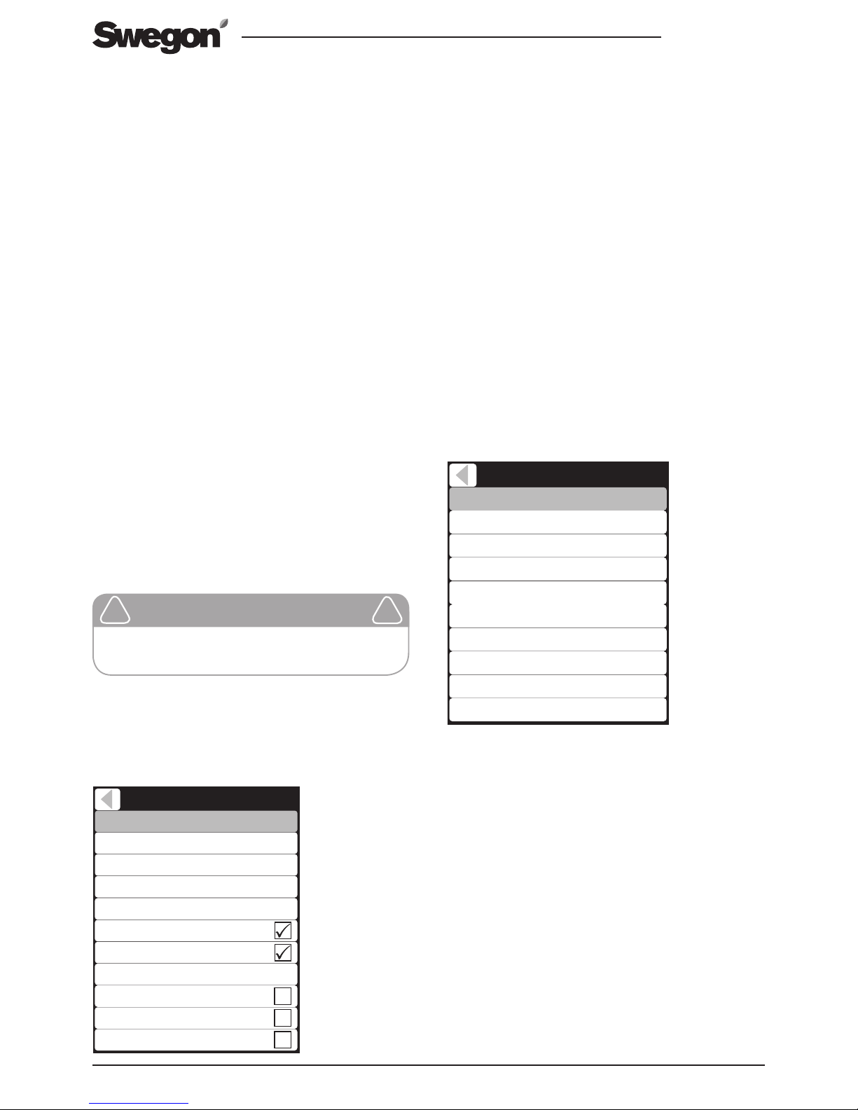
Heating function
Put the heating function into service from the menu
item External after heater.
When using the air heater, heating always occurs
primarily through control of the air heater, yet if the
air heater’s heating capacity is insufficient to maintain
the required temperature or if the freeze protection is
activated, a possible internal electrically powered air
heater in the unit is also controlled. Thus, do not turn
off the internal air heater for after-heating when using
external after heating.
Outdoor air limit
If necessary set Outdoor air limit after heating. After
heating is permitted when the outdoor temperature falls
below the set value.
Select the functions for the temperature sensors used
and fine adjust the measurements if necessary from the
Sensor/Control menu.
Supply air sensor
Select the SET sensor input to which supply air sensor is
connected:
“SET T6 -T9” = SET-connection unit’s Sensor inputs.
“Internal” = The unit’s internal supply air temperature sensor.
Air heater sensor (freeze protection)
Select the SET sensor input to which supply air heater
sensor is connected:
“SET T6 -T9” = SET-connection unit’s Sensor inputs.
Room air sensor
Select the room air sensor which is used:
“Internal” = The unit’s internal extract air temperature sensor.
“SET T6 -T9” = SET connection’s Sensor inputs.
“UP1” = Internal temperature sensor in CASA Smart
control panel 1.
Sensors / controls
Fine tuning Room air
Room air sensor
0,0°C
Supply air
22,2°C
Fine tuning Supply air
Supply air sensor
0,0°C
Outside air sensor
Water radiator sensor
SET Relay 1
SET Relay 2
Internal
Internal
Off
Off
Internal
Internal
18,2°C
The commissioning of the air heater is performed with a
Smart control panel.
Main menu/Settings/(1234)/Heating and cooling
4. Commissioning
Important
Only a qualified electrician may make the
electrical connections.
!
!
3.3 Electric and control cables
• Install the SET-connection unit in an appropriate position in the vicinity of the sensor and actuator. Connect
the CAT45 cables (2 pcs.) supplied with the SET unit to
the specified connections on the ventilation unit.
• Install the supplied temperature sensor in the supply air
duct, after the air heater seen from the direction of flow.
• Connect the sensor to the SET module’s free Sensor
connection.
• Install it in the supplied anti-frost sensor by taping it
to the heater’s return pipe. Make sure the sensor is
sufficiently insulated so that the ambient temperature
does not affect the measurement. Connect the
sensor to the SET module’s free Sensor connection.
• Connect the valve motor control and the power
source supplied with the delivery to the connections
shown on the function diagram.
• Install a possible room temperature sensor (PRTG,
accessory) in the room area whose temperature the
system should control. Connect the sensor to the SET
module’s free Sensor connection.
• Install any actuators according to the manufacturer’s
instructions and connect the control cable to the SET
card’s relay outputs according to the function diagram.
NOTE! If the SET module is used for 230 VAC control,
the module must be installed, according to the electrical
safety directives, in a separate enclosure.
NOTE! Make sure that the strain relief is arranged for the
connections according to the electrical safety directives.
Heating and Cooling
Control type
Setpoint
Setpoint (Away)
17°C
Sensors / controls
Supply air
Setpoint (Travelling)
Internal post heater
17°C
External post heater
Post heater out limit
External post cooling
17°C
External electric preheater
External liquid coil
8°C
Page 5
SDHW. 180118
03/06/2015 Swegon reserves the right to make changes.
5
www.swegonhomesolutions.com
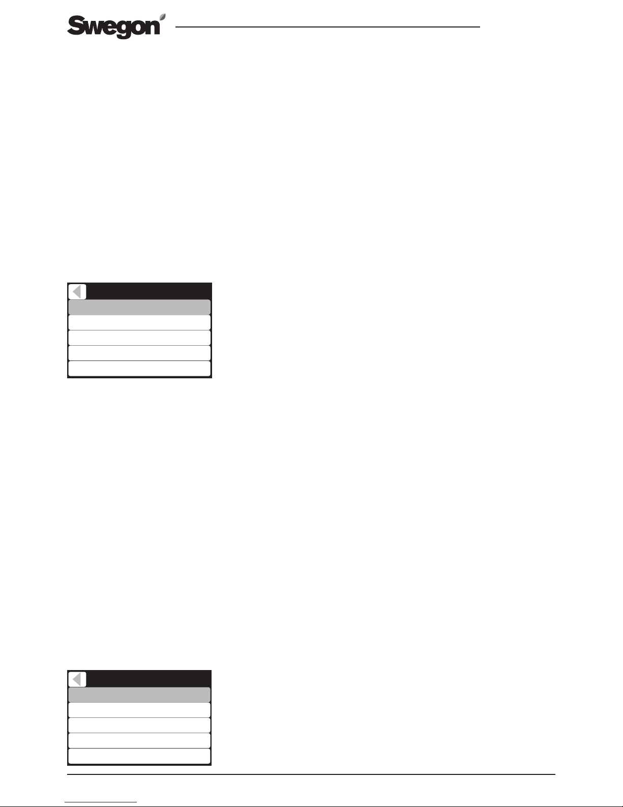
Control of cooling can be observed from a diagnostics
screen. Main menu/Diagnostics/Heating and cooling.
Depending on the selected control mode, the set point
value is shown for room air control’s supply air or the set
point value for supply air control, the measured supply
air temperature and the heating and or cooling capacity.
Temperature boost
if the after heating works as the home’s primary heating
source and room air control is selected, you can use
heating boost. The function increases the ventilation
capacity variably to improve the efficiency of heating.
The function is put into service from the “Smartfunctions” menu Main menu/Settings/Smart functions/
Temperature boost The efficiency of the temperature
boost can be regulated by changing the heating boost.
Temperature boost works automatically, but it can be
temporarily taken out of service by changing the ventilation mode. Boost will then be out of service for the
following six hours. During temperature boost you can
select Away and Boost speeds as normal. However, you
can decide whether the function should be permitted in
Away mode from the temperature boost menu.
Freeze protection
The air heater is equipped with anti-frost sensor that protects the air heater from freezing. The freeze risk alarm is
activated if the outdoor temperature is below 0 °C and
the return water temperature drops below the alarm
limit. If the return water’s temperature drops yet further,
the unit is switched off to prevent freezing. The unit
starts again, when the temperature of the return water or
the outdoor temperature has risen to a safe level.
The unit must be cleaned at regular intervals to obtain full
power from the air heater. The length of the service interval is entirely dependent on the cleanliness of the air, and
of how well the filters and unit are maintained in general.
The air heater can be easily cleaned once the heater’s
cover has been removed. The inlet side of the air heater
is cleaned first with a brush, and then you can clean the
entire air heater with compressed air, water or steam.
Blow or wipe off dirt in the direction from the output
side towards the input side. Exercise care so that the
thin edges of the fins are not damaged.
6. Service
Stop the ventilation before servicing.
“UP2” = Internal temperature sensor in CASA control panel 2.
Relay control functions
If you wish to use relay control functions, e.g. for a
circulation water pump or a duct damper, the SET unit’s
relays can be programmed for the required function
from the Sensor/Control menu.
5. Use and function
The after heating is regulated automatically when the
outdoor temperature has fallen below the set limit value.
You can select supply air or room air control as the after
heating control method. Main menu/Settings/(1234)/
Heating and cooling/Control methid
Supply air control
During the heating season you should attempt to keep
the supply air stable.
NOTE! Due to the high efficiency of the heat exchanger,
the supply air temperature may be higher than the set
point value even though the outdoor air is cool.
Room air control
For room air control, the temperature of the supply air is
based on the measurement of the room air temperature.
It is possible, from the Control mode menu, to select the
highest and lowest set point for cooling and heating to
the supply air. The heating values should be kept close to
the comfort temperature for the heating season.
The control’s set point
The set point can be changed directly from the Main menu.
From the Heating and cooling menu you can also select
separate set point values for Away and Travelling modes.
Diagnostics
Control type
Control type
Supply control max value
Cooling min setpoint
17°C
Supply control min value
Room air
Cooling max setpoint 25°C
14°C
17°C
Heating and Cooling
Eftervärme effekt
Supply air temperature
Summer mode
16,5°C
Supply air setpoint
0%
Preheater status 0%
100%
17°C
Page 6
6
SDHW. 180118
03/06/2015 Swegon reserves the right to make changes.www.swegonhomesolutions.com
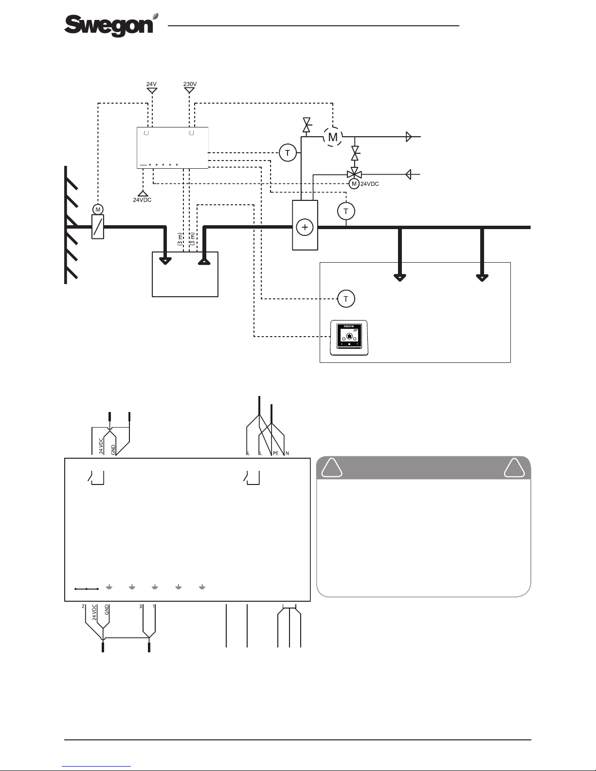
7. Function diagram and connections
Smart Extension Temperature module
Sensor
T6 T7
T8 T9
Smart unit
SET2 SET1
DI
max 50 VDC
NC NC NC
1 2 3 4 5 6 7 8 9 10 11 12
max 250 V / 6 A
Relay 1
4 3 2 1
max 250 V / 6 A
Relay 2
NC
4 3 2 1
AO3AO2AO1
NC
NC NC
SET
1
2
3
15
5
6
7
8
9
10
11
12
(1 m)
(3 m)
(3 m)
13
14
4
16
(3 m)
1: CASA Smart ventilation unit* | 2: SDHW air heater | 3: 3-way valve | 4: Actuator | 5: SET connection unit | 6: Power source 24 VDC
| 7: Supply air temperature sensor | 8: Room air temperature sensor* | 9: Control panel | 10: Circulation water pump* | 11: Extract air
| 12: Flow regulator | 13: CAT45 cable (2 pcs.) | 14. Modular cable PMK20* | 15. Duct actuator* | 16. Air heater’s anti-frost sensor*
*) Not included in the delivery.
Smart Extension Temperature module
Sensor
T6 T7
T8 T9
Smart unit
SET2 SET1
DI
max 50 VDC
NC NC NC
1 2 3 4 5 6 7 8 9 10 11 12
max 250 V / 6 A
Relay 1
4 3 2 1
max 250 V / 6 A
Relay 2
NC
4 3 2 1
AO3AO2AO1
NC
NC NC
SET
11
64
167
230 V
10
6 15
8
Important
If the SET module is used for 230 VAC
control, the module must be installed,
according to the electrical safety
directives, in a separate enclosure.
Make sure that the strain relief is
arranged for the connections according to
the electrical safety directives.
!
!
Page 7
SDHW. 180118
03/06/2015 Swegon reserves the right to make changes.
7
www.swegonhomesolutions.com
Airflow
l/s m
3
/h
Pressure
loss for
air
Pa
Air in ºCAir outºCCapac-
ity,
kW
Water
flow
l/s
Pres-
sure
loss for
air
kPa
Air out
ºC
Capac-
ity,
kW
Water
flow
l/s
Pres-
sure
loss for
air
kPa
Air out
ºC
Ca-
pacity,
kW
Water
flow
l/s
Pressure
loss for
air
kPa
40 90 9
0
57.8 3.0 0.04 5.7 40.7 2.1 0.03 3.1 40.9 2.1 0.05 11.3
40 90
9 7.5 59.6 2.6 0.03 4.4 42.3 1.8 0.02 2.2 42.6 1.8 0.04 8.1
40 90
9 15 61.2 2.3 0.03 3.4 43.5 1.4 0.02 1.5 44.1 1.4 0.03 5.5
70 250
23 0 50.8 4.6 0.06 12.2 35.6 3.2 0.04 6.6 36.1 3.3 0.08 24.4
70 250
22 7.5 53.2 4.0 0.05 9.5 37.8 2.7 0.03 4.7 38.5 2.7 0.07 17.4
70 250
22 15 55.6 3.4 0.04 7.2 39.8 2.1 0.03 3.1 40.7 2.2 0.05 11.7
100 360
41 0 45.8 5.9 0.07 19.3 32.0 4.1 0.05 10.3 32.7 4.2 0.10 39.0
100 360
40 7.5 48.8 5.1 0.06 15.0 34.7 3.4 0.04 7.3 35.5 3.5 0.08 27.7
100 360
39 15 51.6 4.4 0.05 11.4 37.3 2.7 0.03 4.8 35.1 2.4 0.06 24.0
CASA air heater for the supply air duct:
CASA air heater
ØD mm
B mm
H mm
Øo.d.
mm
F G mm K mm L mm Pipe
system’s int.
volume I
Weight,
kg
CWW 125 125
313
255 10 175 40 276 356 0.20 5.5
CWW 160
160 313 255 10 175 40 276 356 0.42 5.4
Airflow
l/s
m
3
/h
Pres-
sure
loss for
air
Pa
Air in ºCAir outºCCapac-
ity,
kW
Water
flow
l/s
Pres-
sure
loss for
air
kPa
Air out
ºC
Capac-
ity,
kW
Water
flow
l/s
Pres-
sure
loss for
air
kPa
Air out
ºC
Capac-
ity,
kW
Water
flow
l/s
Pressure
loss for
air
kPa
25 90 4
0
63.7 2.0 0.02 2.6 45.2 1.4 0.02 1.5 44.9 1.4 0.03 5.1
25 90
4 7.5 65.0 1.7 0.02 1.7 46.0 1.1 0.01 1.0 46.0 1.1 0.03 3.6
25 90
4 15 66.9 1.5 0.02 1.5 46.6 0.9 0.01 0.7 47.0 0.9 0.02 2.5
40 140
10 0 57.4 3.1 0.04 5.9 40.4 2.2 0.03 3.3 40.7 2.2 0.05 11.9
40 140
9 7.5 59.2 2.7 0.03 4.7 42.0 1.8 0.02 2.3 42.4 1.8 0.04 8.5
40 140
9 15 60.9 2.3 0.03 3.6 43.3 1.4 0.02 1.6 43.9 1.5 0.04 5.7
60 210
18 0 52.8 4.1 0.05 9.9 37.1 2.9 0.03 5.4 37.5 2.9 0.07 19.8
60 210
17 7.5 55.1 3.6 0.04 7.7 39.1 2.4 0.03 3.8 39.7 2.4 0.06 14.1
60 210
17 15 57.2 3.1 0.04 5.9 40.9 1.9 0.02 2.5 41.7 1.9 0.05 9.5
Water temperature in/out 80ºC/60ºC in/out 60ºC/40ºC in/out 55ºC/45ºC
Water temperature in/out 80ºC/60ºC
in/out 60ºC/40ºC in/out 55ºC/45ºC
CWW 125
CWW 160
Page 8
www.swegonhomesolutions.com
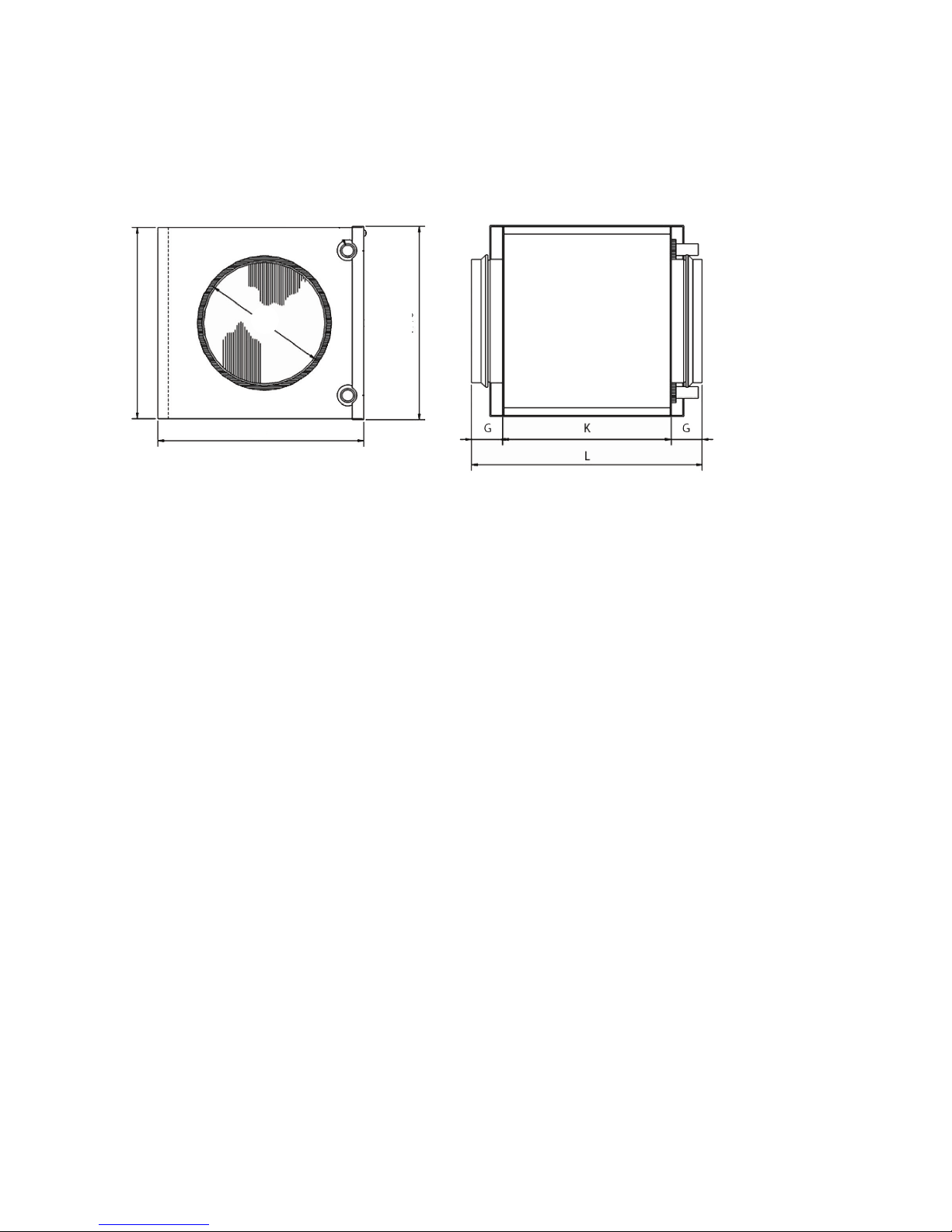
D
B
H+8
H
Leave at least 40 cm service space in front of the
door.
CWW 125
H 255
B 313
D 125
CW W 16 0
H 255
B 313
D 160
CWW 125
K 276
L 356
CW W 16 0
K 276
L 356
8. Dimensions
 Loading...