

Page 1

Installation, operation and maintenance instructions
for design engineers, installation engineers and service personnel
SDHWM_c_EN–m
Swegon CASA® Air heater/cooler in
combination with ground source heat pump
Page 2
2
SDHWM.230817
Swegon reserves the right to make changes.www.swegonhomesolutions.com
Important information
Only qualified personnel
Only qualified personnel should carry out
installation, configuration and commissioning.
Observe the following during
installation
The air heater/cooler is installed in the
outdoor air duct before the ventilation unit.
The air heater/cooler must be mounted so
that the air heater/cooler is horizontal in
relation to the airflow.
The air heater/cooler must not be installed in
the immediate vicinity of the ventilation unit
or duct bends, as this will prevent an even
airflow across the air heater/cooler resulting
in impaired output.
Commissioning
The air heater/cooler’s duct sleeves must
be covered during transport, storage and
installation.
Make sure that the air heater/cooler and the
ducts are clean and that there are no loose
objects in them before you commission the
ventilation system.
Ensure that the heating medium pipe system
is mounted and insulated and that the
venting sleeves are mounted.
Do not commission the air heater/cooler
until all work that produces large quantities
of sanding dust or other impurities has been
completed.
Sizing the heating medium circuit
Consideration must be taken during planning
to the effect of the air heater/cooler.
Ensure that the ground source heating
well cannot freeze on account of the
heater/cooler being added to the system.
Supplement with the necessary protection.
NOTE! The manual’s original language is Finnish.
!
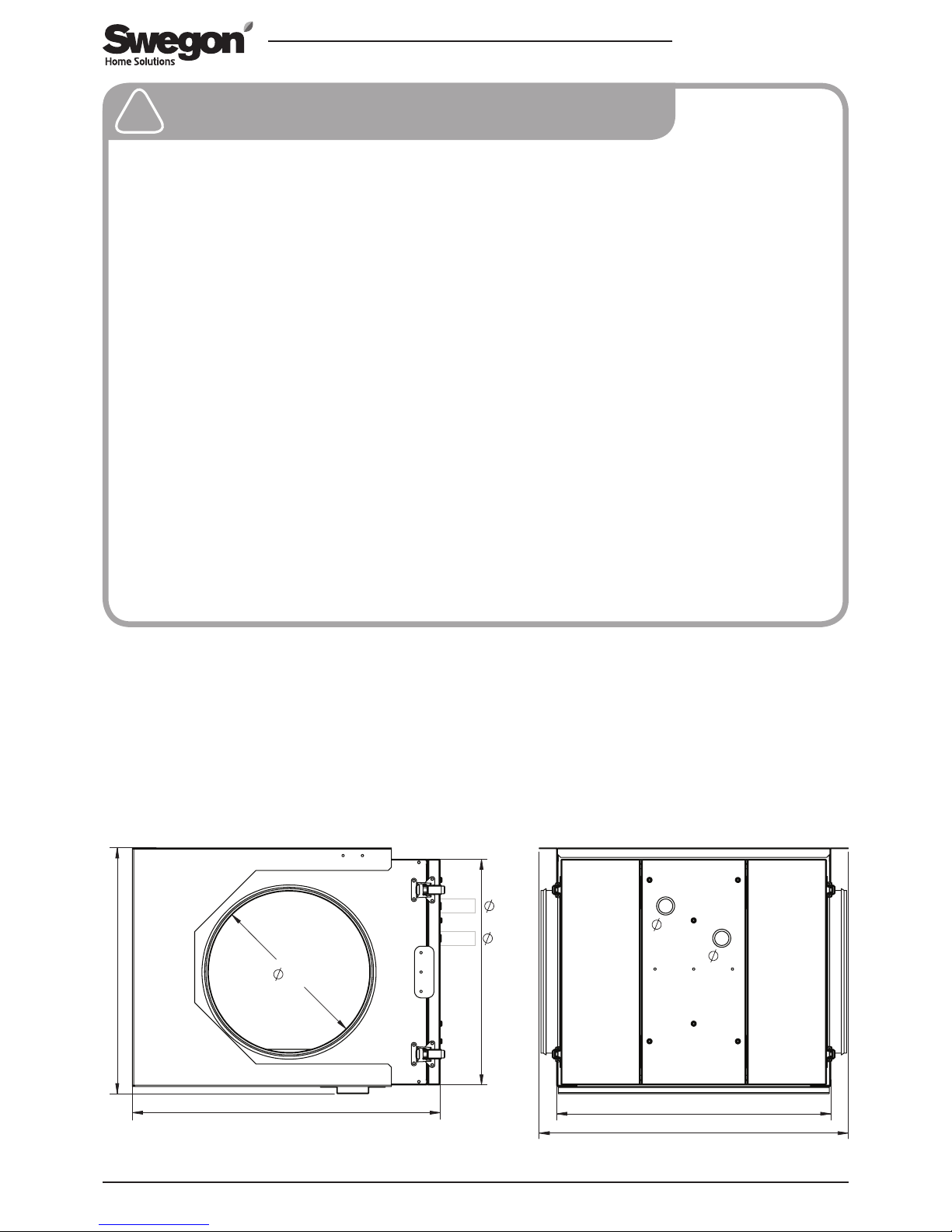
479
425
381
350
250
477
22
22
22
22
Included in the delivery:
• CASA W250F air heater/cooler, fully insulated
• T
emperature sensor (T8) cable length 3 m
• SET connection unit
• RJ45 cable, 3 m, 2 pcs.
• Wall mounting bracket/ceiling mounting frame
• Wide-mesh filter
• Instructions
Accessories:
• Condensate hose W2504F for the air heater/cooler:
502130
Page 3

SDHWM.230817
Swegon reserves the right to make changes.
3
www.swegonhomesolutions.com
3.1. Installation of the air heater/cooler in
the duct system
The unit is installed in the outdoor air duct when connected as preheater/chiller. The air heater/cooler must
be mounted horizontally. Remember that the condensate outlet must be connected to the building's drainage system. There should be at least 500 mm free space
in front of the hatch.
The condensate hose is connected to the condensate
outlet (G3/8"). The condensate is led off to a floor
drain or the like using a hose with an inner diameter
of at least 12 mm. The condensate hose (502130) is
available as an accessory for air heater/cooler W2504F.
The hose must not be led off directly to the drain. There
must be two water traps or a horizontal section on the
condensate hose. The damming height of the water
trap should be at least 100 mm.
Check that the condensate discharge outlet is not
3. Installation
In the winter the air heater/cooler heats the air taken
in and ensures that the ventilation unit operates with
the greatest efficiency even in extreme cold. In the
summer, the medium in the ground circuit is used to
cool the building. The control technology in CASA
Smart ventilation units automatically enables the best
utilisation of the air heater/cooler all year round.
1. General Description
2. Planning
To observe during planning: when sizing the depth of
the ground source heating well, review the capacity
tables in the brochure and take into account the air
heater/cooler’s capacity for the established airflows. To
size the pump, find out the heating medium flow and
the air heater/cooler’s pressure loss. Take the pressure
loss caused by the air heater/cooler into consideration
when sizing the airflows.
The air heater/cooler must always be mounted
horizontally, as condensate is formed during the
summer and this must be led to a drain.
Reserve servicing space at the sides of the unit in the plans.
3.2. Pipe connections for the heating medium
The pipes for the air heater/cooler’s heating medium is
connected to the unit’s pipe connections (Cu 22 mm)
for the outgoing solution and the return solution.
Remember the need to vent the heating medium pipes
in connection with the pipe installation. The air heater/
cooler’s coarse filter must always be installed on the
unit’s outdoor side.
The following must be taken into consideration when
the air heater is connected to the pipe system:
1. The air heater/cooler’s connection pipes must not
be subjected to distortion or bending movements
when the connections are made. Counterhold with
a tool when assembling the couplings.
2. Ensure that the unit’s expansion forces or the pipe
system’s own weight does not load the connections
on the air heater/cooler.
3. To facilitate venting of the air heater/cooler,
heating medium is generally supplied through the
lowermost pipe on the heater/cooler. The venting
valve is normally placed at the highest point of the
pipe system.
4. The air heater/cooler and its connections must be
checked for leakage once the pipe system has been
completely filled.
clogged and check its outflow by pouring water on the
bottom of the ventilation unit.
The condensate pipe must be placed in a heated space.
A condensate pipe that is installed in a cold space
must always be insulated with at least 50 mm mineral
insulation or 30 mm cellular rubber insulation and fitted
with a heating cable.
The ducts are mounted on the air heater/cooler’s
Ø250 mm connection sleeves. The ducts are slid into
the sleeves and locked with pop rivets. Keep in mind
that the ducts’ insulation must run right up to the unit.
After the air heater/cooler, the supply air duct must be
insulated using 10 mm thick mineral wool in both the
heated and cold areas (remember moisture insulation).
The outdoor air duct, the ducts after the air heater/
cooler as well as the outgoing exhaust air duct must
also be insulated against moisture (for example with a
layer of plastic film above the layer with insulation or
cellular-rubber insulation).
Page 4
4
SDHWM.230817
Swegon reserves the right to make changes.www.swegonhomesolutions.com
4. Commissioning
Important
Only a qualified electrician may make the
electrical connections.
!
!
3.3 Electric and control cables
• Install the SET-connection unit in an appropriate
position in the vicinity of the sensor and actuator.
Connect the
RJ45 cables (2 pcs.) supplied with the
SET unit to the specified connections on the
ventilation unit.
• Install the supplied temperature sensor in the outdoor
air duct, before the air heater/cooler seen from the
direction of flow.
• Connect the sensor to the SET module’s free Sensor connection.
• Connect the heating medium pump’s power supply to
the SET-connection unit’s other relay output according to the function diagram.
• Install any actuators according to the manufacturer’s
instructions and connect the control cable to the SET
connection unit’s relay outputs according to the
function diagram.
NOTE! If the SET module is used for 230 VAC control,
the module must be installed, according to the electrical
safety directives, in a separate enclosure.
NOTE! Make sure that the strain relief is arranged for the
connections according to the electrical safety directives.
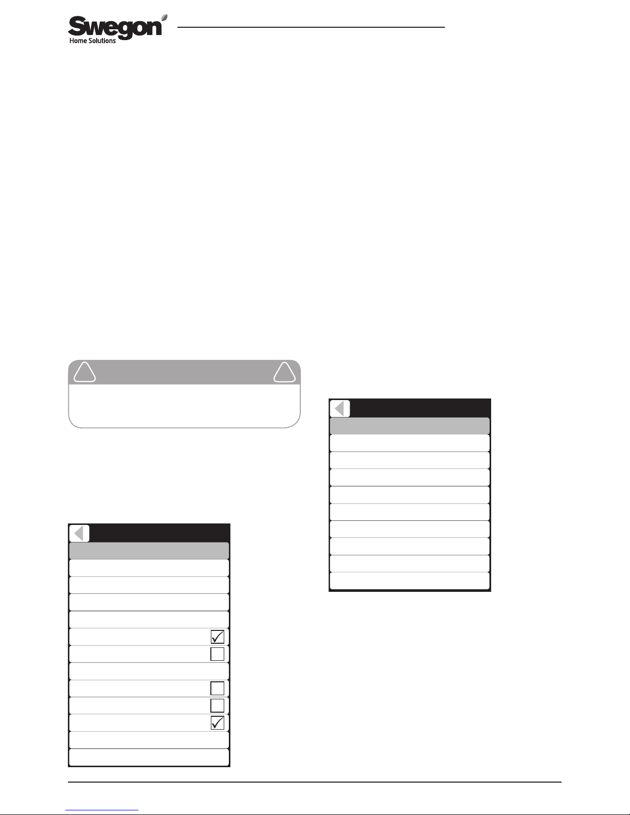
Commissioning the air heater/cooler is performed with
a Smart control panel. Main menu/Settings/(1234)/
Heating and cooling
Heating and Cooling
Control type
Setpoint
Setpoint (Away)
17°C
Sensors / controls
Supply air
Setpoint (Travelling)
Internal post heater
17°C
External post heater
Post heater out limit
External post cooling
17°C
External electric preheater
External liquid coil
8°C
Liquid heating out limit
Liquid cooling out limit 15°C
-2°C
Commissioning of the air heater/cooler
Select operation of the unit by highlighting the menu
item External after heater.
Limit value (heating)
Select the required start temperature for external preheating. When the outdoor temperature (transferred
outside temperature) measured before the air heater/
cooler drops below the limit value, the relays in the SET
unit selected for the heat medium pump are activated.
The operating signal is received from the relay output, for
example, the heat medium pump and/or solenoid valve.
Limit value (cooling)
Select the required start temperature for external precooling. When the outdoor temperature (transferred outside
temperature) measured before the air heater/cooler rises
above the limit value, the relays in the SET unit selected
for the heat medium pump are activated. The operating
signal is received from the relay output, for example, the
heat medium pump and/or solenoid valve.
Select the functions for the temperature sensors used
and fine adjust the measurements if necessary from the
Sensor/Control menu.
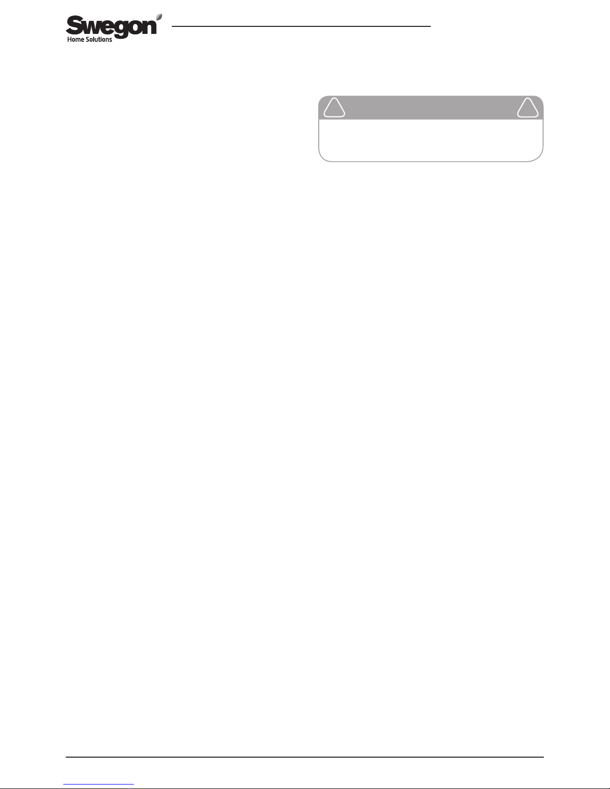
Outdoor air sensor
Select the SET sensor input (T6–T9) to which outdoor air
sensor is connected:
“SET T6 -T9” = SET-connection unit’s Sensor inputs.
“Internal” = The unit’s internal outdoor air temperature
sensor.
Relay control functions
Select the heat medium pump function for the SETconnection unit’s relays. SET Relay 1 / SET Relay 2 =
Heat medium pump.
Sensors / controls
Fine tuning Room air
Room air sensor
0,0°C
Supply air
22,2°C
Fine tuning Supply air
Supply air sensor
0,0°C
Outside air sensor
Water radiator sensor
SET Relay 1
SET Relay 2
Internal
Internal
Off
Off
Internal
Internal
18,2°C
Page 5
SDHWM.230817
Swegon reserves the right to make changes.
5
www.swegonhomesolutions.com
Preheating with the heating medium is performed
automatically according to the outdoor temperature
through the unit’s incoming air being heated in the
winter and cooled in the summer. A minimum operating
time (10 minutes) has been set for control of the
heating medium pump.
5. Use and function
The unit’s doors can be lifted from their hinges after
their fastening catches have been opened.
The radiator in the unit, can e.g. be cleaned by gently
brushing the surface or gentle rinsing with water (only
at low pressure). Any dirt that has accumulated on the
bottom of the condensate tray can be wiped off using a
cloth and mild detergent.
The function of the water trap and drainage pipes for
condensate water should be checked at least twice a
year by pouring water in the bottom of the condensate
tray.
6. Service
Important
Stop the ventilation before servicing.
!
!
Page 6
6
SDHWM.230817
Swegon reserves the right to make changes.www.swegonhomesolutions.com
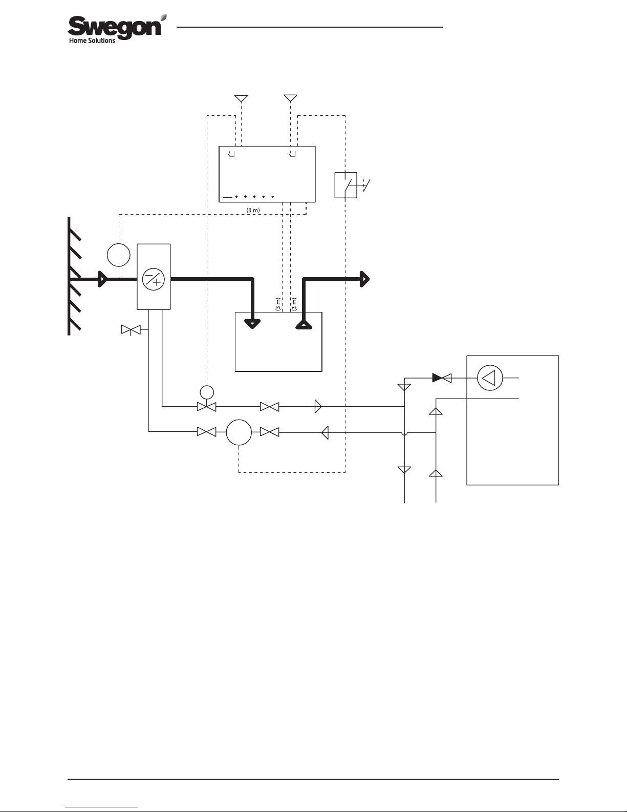
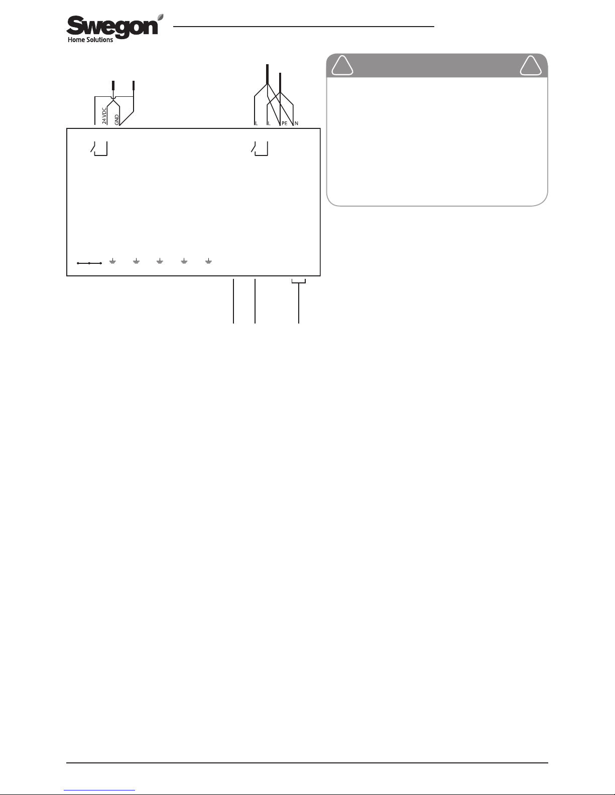
7. Function diagram and connections
1: CASA Smart ventilation unit* | 2: SDHWM air heater-cooler | 3: Outdoor air temperature sensor | 4: SET connection unit | 5: Heat
pump* | 6: Solenoid valve* | 7: Circulation water pump* | 8: Extract air | 9: Power source 24 VDC* | 10: Operating switch for the
circulation water pump ON/OFF*
*) Not included in the delivery.
M
M
T
230V24V
24VDC
Smart Extension Temperature module
Sensor
T6 T7
T8 T9
Smart unit
SET2 SET1
DI
max 50 VDC
NC NC NC
1 2 3 4 5 6 7 8 9 10 11 12
max 250 V / 6 A
Relay 1
4 3 2 1
max 250 V / 6 A
Relay 2
NC
4 3 2 1
AO3AO2AO1
NC
NC NC
SET
1
2
3
5
6
7
8
4
9
10
10
Page 7
SDHWM.230817
Swegon reserves the right to make changes.
7
www.swegonhomesolutions.com
Smart Extension Temperature module
Sensor
T6 T7
T8 T9
Smart unit
SET2 SET1
DI
max 50 VDC
NC NC NC
1 2 3 4 5 6 7 8 9 10 11 12
max 250 V / 6 A
Relay 1
4 3 2 1
max 250 V / 6 A
Relay 2
NC
4 3 2 1
AO3AO2AO1
NC
NC NC
SET
11
230 V
7
9 6
3
Important
If the SET module is used for 230 VAC
control, the module must be installed,
according to the electrical safety
directives, in a separate enclosure.
Make sure that the strain relief is
arranged for the connections according to
the electrical safety directives.
!
!
1: CASA Smart ventilation unit* | 3: Outdoor air temperature sensor
| 6: Solenoid valve* | 7: Circulation water pump* | 9: Power source
24 VDC* |
*) Not included in the delivery.
Page 8
www.swegonhomesolutions.com
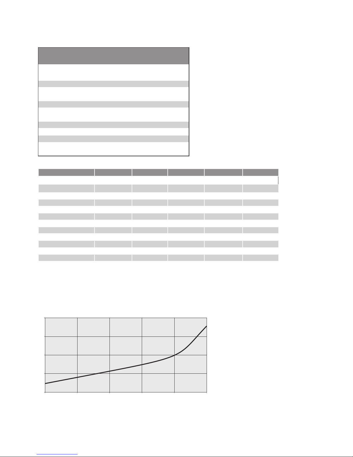
Pre-heating:
Capacity, kW 1.0 1.4 1.5 1.7 1.8
Air flow l/s 40 60 70 90 100
Incoming air °C -26 -26 -26 -26 -26
Outgoing air
°C
-5 -7 -8 -10 -11
Air’s velocity, m/s 0.4 0.7 0.8 1.0 1.1
Pressure loss for air Pa 5 9 11 16 19
Incoming fluid
ºC
2 2 2 2 2
Outgoing fluid
ºC
-2 -2 -2 -2 -2
Fluid flow l/s 0.06 0.08 0.09 0.11 0.11
Fluid velocity m/s 0.3 0.3 0.4 0.4 0.5
Fluid’s pressure loss kPa 5.9 7.9 8.7 10.0 10.6
Pipe connection DN 25 25 25 25 25
Air heater/cooler’s performance data:
The unit's function for use as a preheater has been sized with 28% ethanol
Air heater/cooler’s performance data
Cooling:
Capacity, kW
0.8
1.2 1.4
Air flow l/s
40
100 150
INCOMING AIR
Temperature °C
25
25 25
Relative humidity % 55
55 55
OUTGOING AIR
Temperature °C
13
17 18
Relative humidity % 95
87 82
INCOMING FLUID
Temperature °C 4 4 4
OUTGOING FLUID
Temperature °C 9 8.5 9.5
Fluid flow dm³/s 0.04 0.06 0.07
0
10
20
30
40
40 60 70 90 100
150
Airflow rate l/s
AIR HEATER/COOLER
Pressure loss
Pa
 Loading...