

Swegon ADAPT Parasol EXb Series, ADAPT Parasol EXb 690, ADAPT Parasol EXb 1290 Installation, Commissioning Maintenance
Page 1
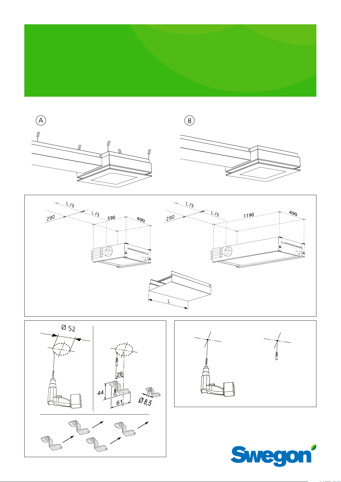
ADAPT Parasol EXb
Installation – Commissioning – Maintenance
Installation
A1, B1
20191101
Art. 942428024
B2A2
Page 2
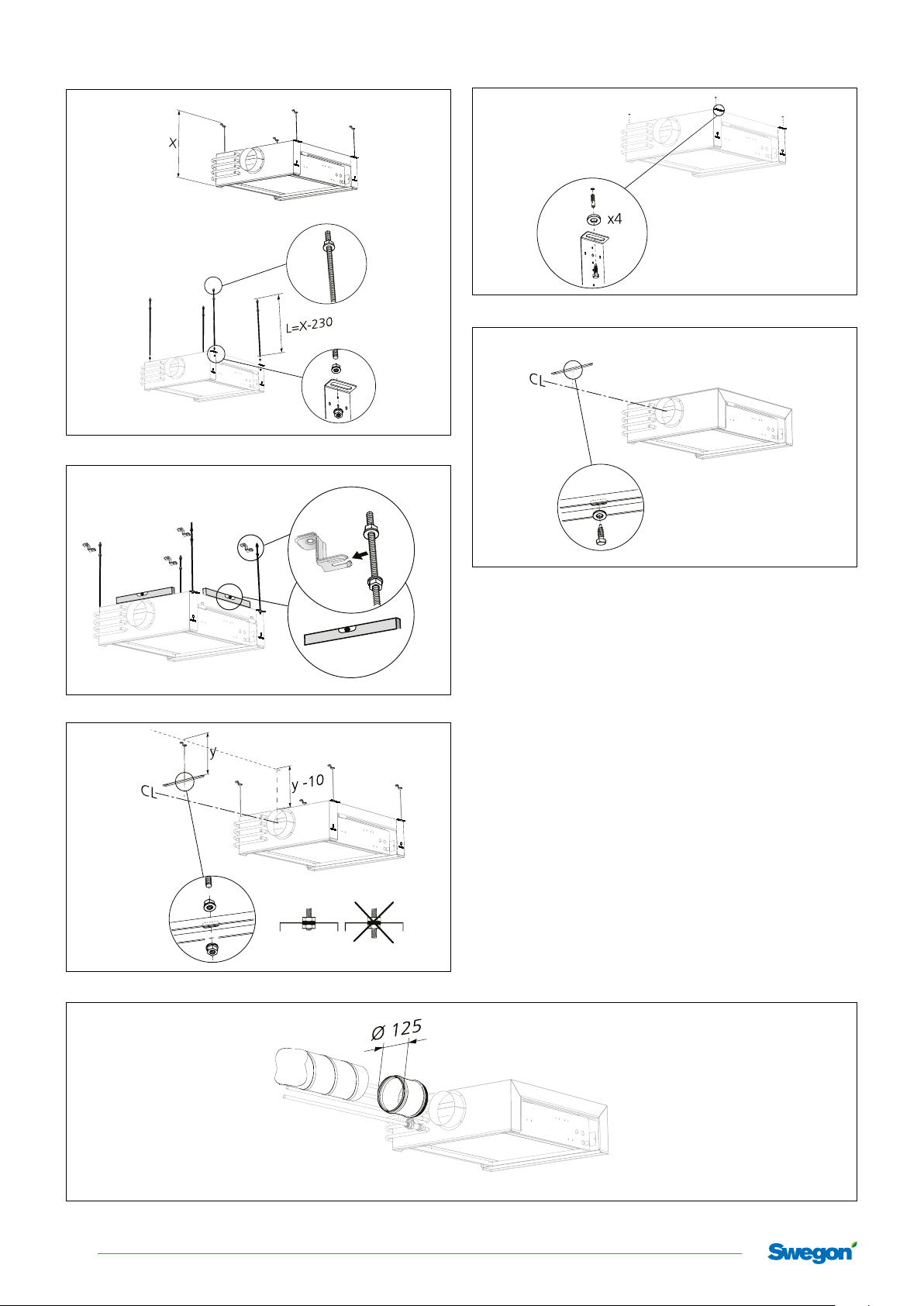
ADAPT Parasol EX
A3
A4
B3
M8
B4
A5
A6, B5
2
Swegon reserves the right to alter specications. 20191101
Page 3
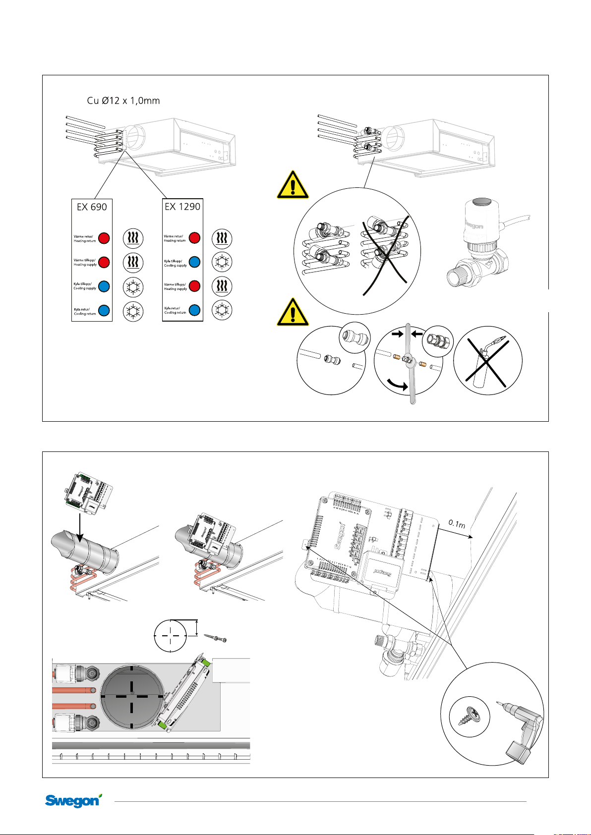
d/2
Water
A7, B 6
ADAPT Parasol EX
DN15 (1/2”) male threads
utvändig gänga DN (1/2”)
Control equipment
A8, B7
Note that clamp ring couplings require support sleeves inside the pipes.
20191101 Swegon reserves the right to alter specications.
3
Page 4
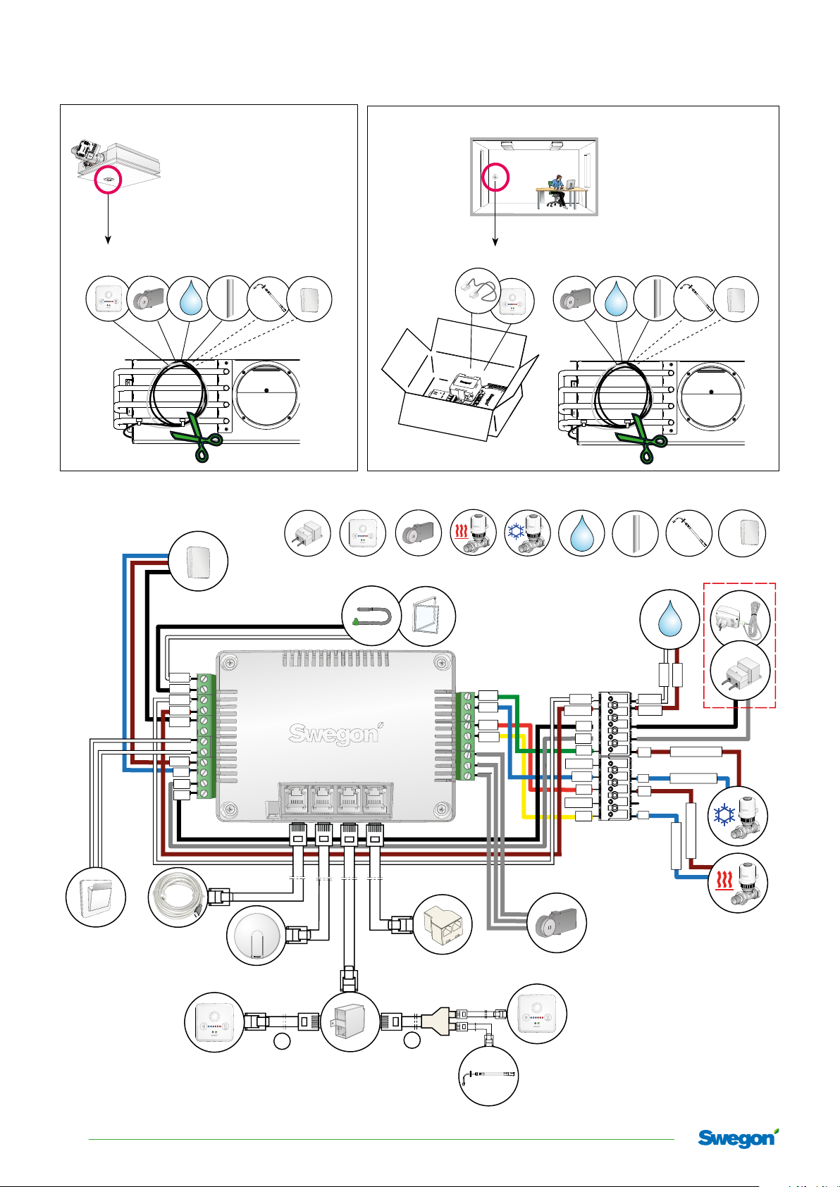
ADAPT Parasol EX
B
Wiring
A9, B8
B C F G H I
A10 , B9
A9, B8
C F G H I
RoHS
A B C D E F G H I
VOC
RoHS
S
oH
R
CO
2
|
white
black
white
brown
black
brown
blue
grey
black
1
2
|
3
4
|
5
6
|
7
8
|
9 10
11
12
|
1. Wiring when not using VOC sensor
2. Wiring when using VOC sensor
| 22 | 23 | 24 | 25 |
1.
white
21 |
20
18 |19
17
|13 14 15 |16
green
blue
red
yellow
Sensor
Condens
G0
G
24V
0-10V DC
G0
24V
0-10V DC
G0
Sensor
Condens
24V
G0
24V
G0
brown
brown (US=white)
blue (US=black)
brown (US=white)
blue (US=black)
2.
RoHS
4
Swegon reserves the right to alter specications. 20191101
Page 5
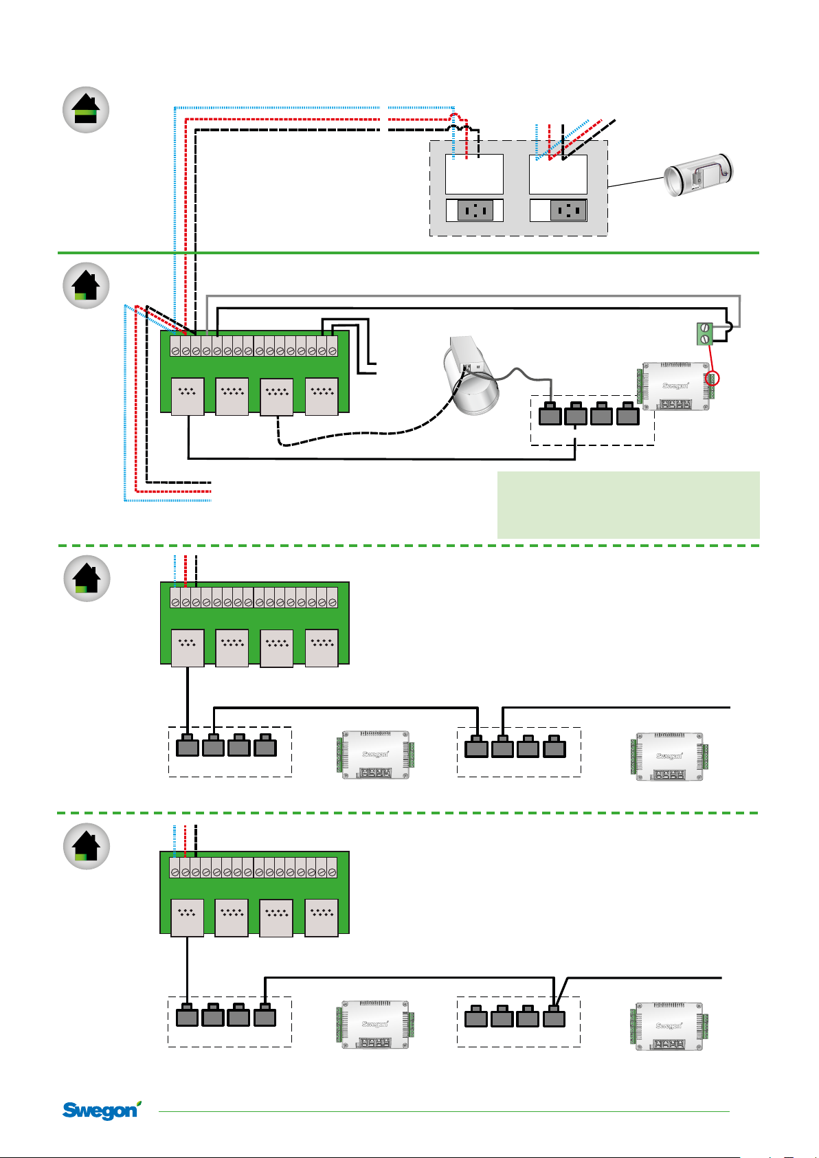
ADAPT Parasol EX
Zone
Room
RS 485 type Belden 9842
RK 2x0,75
CONNECT Adapt
1 2 3 4 5 6 7 8 9 10 11 12 13 14 15 16
23
Modbus
22
Slave
Slave
21
Master
20
Modular
6/6 RJ12
Next room with Connect Adapt
+
C
G0
24V AC
G
Modular
8/8 RJ45
Next Zone
1 2 3 4
MB2
Super WISE
5 6 7 8
MB1
1 2 3 1 2 3
Room with ADAPT Damper extract air
MB id 5
Slave, extract air
ADAPT Damper settings
• Slave MB id (5,6,7,9,10,11 etc. if Super WISE system)
• Slave function (Application type =3 )
• Extract Air (Tempsensor use =1)
• Operation = normal (commissioning mode when delivered)
Modular
6/6 RJ12
22 23 24 25
| 1 2 | 3 4 | 5 6 | 7 8 | 9 10 11 12 |
CONTROL
MB id 1
| 22 | 23 | 24 | 25 |
Zone
20
19
|13 14 15 | 16 17 18 | 19 20 21 |
MB id 4
Master
Room
Room
Modular
6/6 RJ12
CONNECT Adapt
Slave
Modbus
23
22
22 23 24 25
MB id 4
Master
CONNECT Adapt
Slave
Modbus
23
22
21
21
Slave
Slave
1 2 3 4 5 6 7 8 9 10 11 12 13 14 15 16
Master
20
Modular 6/6 RJ12
| 1 2 | 3 4 | 5 6 | 7 8 | 9 10 11 12 |
| 22 | 23 | 24 | 25 |
1 2 3 4 5 6 7 8 9 10 11 12 13 14 15 16
Master
20
Room with ADAPT Parasol only (Master / Master)
Modular 6/6 RJ12
| 1 2 | 3 4 | 5 6 | 7 8 | 9 10 11 12 |
|13 14 15 | 16 17 18 | 19 20 21 |
22 23 24 25
| 22 | 23 | 24 | 25 |
|13 14 15 | 16 17 18 | 19 20 21 |
MB id 8
Master
Room with ADAPT Parasol only (Master / Slave)
Modular
6/6 RJ12
22 23 24 25
MB id 4
Master
Modular 6/6 RJ12
| 1 2 | 3 4 | 5 6 | 7 8 | 9 10 11 12 |
| 22 | 23 | 24 | 25 |
20191101 Swegon reserves the right to alter specications.
Modular 6/6 RJ12
| 1 2 | 3 4 | 5 6 | 7 8 | 9 10 11 12 |
|13 14 15 | 16 17 18 | 19 20 21 |
22 23 24 25
| 22 | 23 | 24 | 25 |
|13 14 15 | 16 17 18 | 19 20 21 |
MB id 1
Slave id 1
5
Page 6
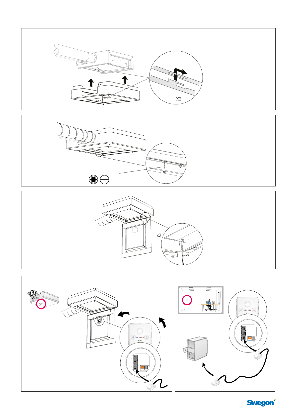
ADAPT Parasol EX
A11, B10
A12 , B11
A13, B12
A14 , B13
TORX T-25 / 1 x 8
Click!
6
Swegon reserves the right to alter specications. 20191101
ON
1 2
ON
1 2
Page 7
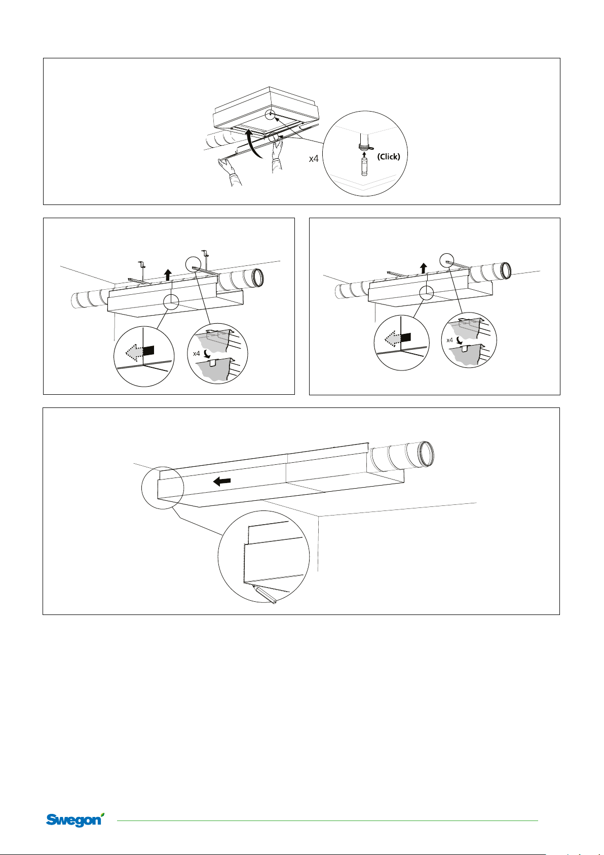
A15 , B14
A16 B15
ADAPT Parasol EX
A17, B16
20191101 Swegon reserves the right to alter specications.
7
Page 8
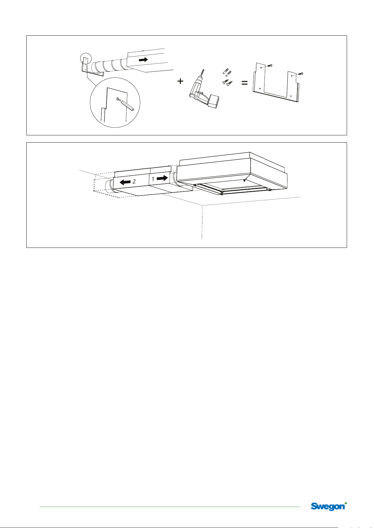
ADAPT Parasol EX
A18 , B17
A19 , B18
8
Swegon reserves the right to alter specications. 20191101
Page 9
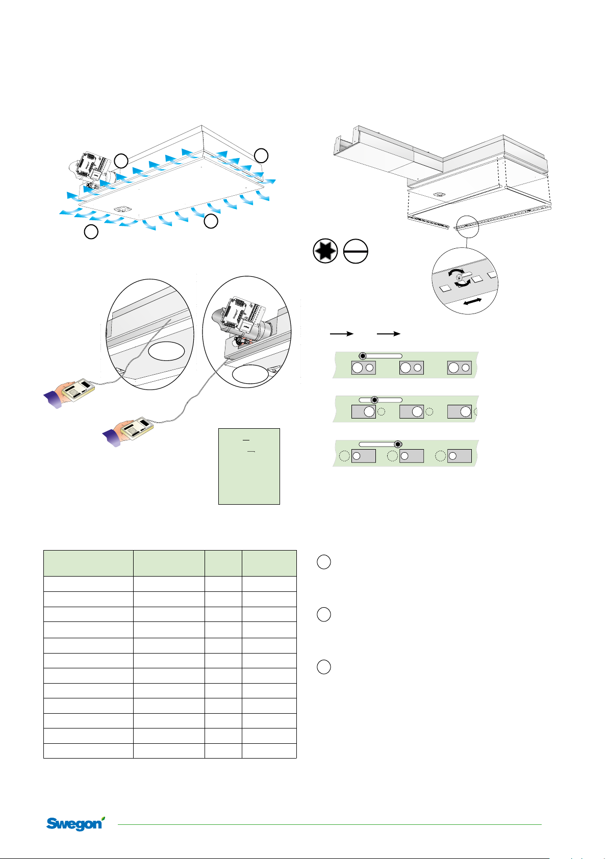
Commissioning
ADAPT Parasol EX
2
3
4
1
T-25
1 x 8
Nozzle configuration
H M L
Pi (2,4)
H =
(1,3)
P
i
M=
2
q
p = [Pa]
(
i
)
k
q = k · √p [l/s]
i
L=
[pi Pa]
q [l/s]
k = k-factor
ADAPT Parasol EX
690 L 1&3 0,253
690 L 2&4 0,253
690 M 1&3 0,44
690 M 2&4 0,44
690 H 1&3 0,693
690 H 2&4 0,693
129 0 L 1&3 0,253
129 0 L 2&4 0,665
129 0 M 1&3 0,44
129 0 M 2&4 1,16
129 0 H 1&3 0,693
129 0 H 2&4 1,825
Nozzle setting
per side
Side
k-factor
k (1+3) + pi (1,3) => q (1+3)
1
The K-factor of the short sides together with the
commissioning pressure reading of these equals
the flow of the short sides, 1&3.
k (2+4) + pi (2,4) => q (2+4)
2
The K-factor of the long sides together with the
commissioning pressure reading of these equals
the flow of the long sides, 2 & 4.
q tot =q (1+3) + q (2+4)
3
The product's total flow is the sum of the above.
(1,3) = pi (2,4)
NB! p
/
i
NOTE: The commissioning pressure is different for the long sides (2 & 4) and the short
sides (1 & 3).
20191101 Swegon reserves the right to alter specications.
9
Page 10
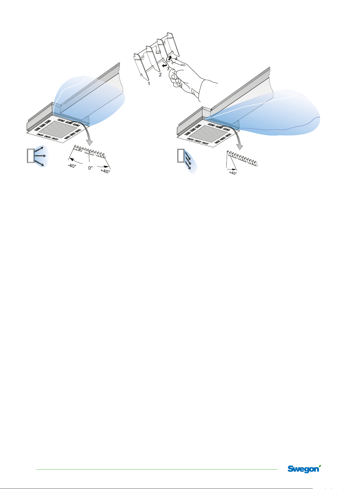
ADAPT Parasol EX
Fan-shape
X-shape
Commissioning/Checking the airflows
Constant pressure in the zone with the CONTROL Zone
damper or similar damper.
• Check that all the WISE products are energized.
• Make sure that all the ADAPT Parasol EX modules have
their correct K-factors.
• Make sure that all the modules are set to the max. flow
commissioning mode. (On delivery, the product is set to
this mode, 3 blue LEDs + 3 red LEDs are lit).
• Connect up to the control unit on the ADAPT Parasol EX
(see separate SWICCT instructions) and carry out a performance check.
• Test the operating modes, the min./max. flows, open/
close the actuators. If the ADAPT Parasol EX has been
configured at the factory, check that the settings agree
with the project design data. If the module is an ADAPT
Parasol EX stock (stocked product), it must be programmed according to the data for which the product has
been calculated. Make also sure that the Modbus addresses agree if SuperWISE or some other BMS system will be
used.
• If SuperWISE will be used, make sure that all products are
in the SuperWISE tree structure. If all the products are
not in the tree structure, look over the Modbus addresses
via SWICCT and check cables and connections. (See the
separate instructions for the SuperWISE).
• Make sure that the pressure sensor and sensor module
have the correct Modbus address. The Master must have
a 0 setting on the pressure sensor and sensor module. Set
the Slaves, if required, in number sequence: 1, 2, 3, 4, 5,
6, 7, 8, 9
• Before you begin commissioning, make sure that the air
handling unit is started up and the fire damper, if required, is fully open and that the zone damper is in full
operation.
• Check the flow compared to the max. flow in the zone,
adjust the pressure set point until the correct flow is obtained with TUNE Control. If Max. flow is not achieved, it
will be necessary to close another/other zone damper(s).
• The reference product can be found, i.e. the one with the
greatest deviation from the design max. flow, by measuring the max. flow of all the ADAPT Parasol EX modules in
the zone.
• Measure and record the airflow with the damper set to
the max. position on the reference ADAPT Parasol EX
in the zone. Reset the module to the min. flow setting,
measure and record the airflow.
• Set the module back to the max. flow setting.
• Carry out the same procedure for all the ADAPT Parasol
EX modules in the zone.
• Decrease the pressure set point on the zone damper if
pressure is needed for other zones, for example: 5 Pa.
• Commission the remaining zones following the same
procedure.
• Check/ adjust the previous shut off zones in the same
way.
• Reset the pressure set points on all the zone dampers.
• Identifiy the reference zone, i.e. the zone with the lowest
flow compared with the design max. flow (for example
by checking relevant flow across each zone damper using
the TUNE Control hand-held terminal).
• Set the min. flow on a number of ADAPT Parasol EX modules or use the zone damper for setting the min. flow so
that the ventilation system responds to the simultaneous
load.
• Adjust the pressure set point of the air handling unit
until the zone damper of the reference zone is 85 – 90%
open. (Managed by the SuperWISE if one is used).
• Reset all the settings and set all the ADAPT Parasol EX to
the normal operation setting.
• Check and measure the max. flow and min. flow with the
SWICCT or the SuperWISE.
10
Swegon reserves the right to alter specications. 20191101
Page 11
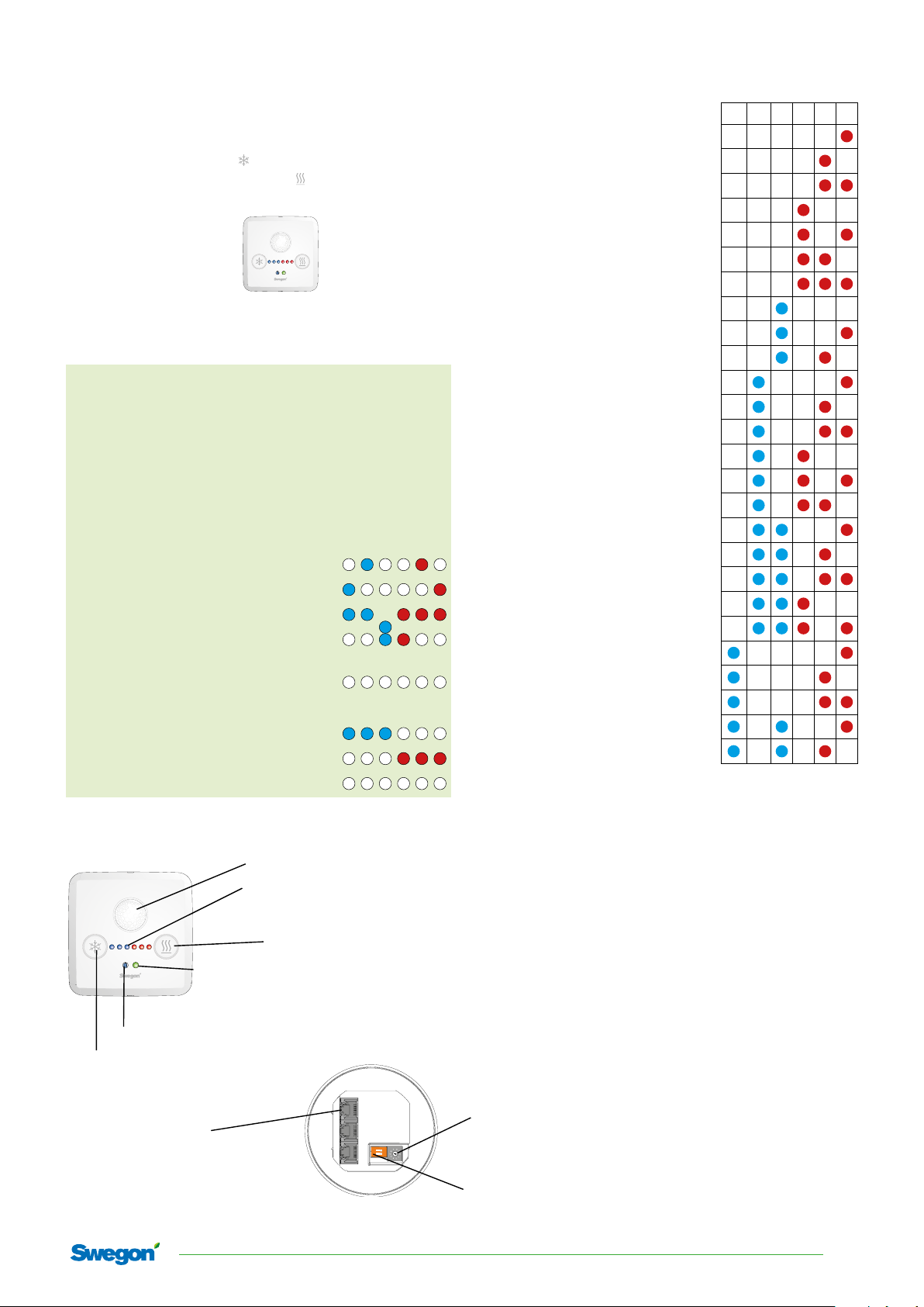
ADAPT Parasol EX
Menu:
To reach the menu, hold the left-hand and right-hand
buttons down for five seconds.
With the left-hand button ( ) you advance through the
menus. With the right-hand button ( ) you confirm your
selection.
Press the left-hand button and select:
1. Alarm list
2. Commissioning air
Press the righthand button to
confirm your
selection
3. Commissioning water
6. Return to menu
1. Alarm list: See the complete alarm list to the right.
In the commissioning menus:
• Navigate between the menus by pressing the left-hand
button
• Confirm selections by pressing the right-hand button
• When a selection has been confirmed, the blue LED will
flash for about 60 seconds.
• In order to return to normal operation, select "no adjustment"
2. Commissioning, Air:
2.1. Min. airflow, no occupants
2.2. Min. airflow, occupancy
2.3. Max. airflow, occupancy
2.4. Min. airflow, holiday/longer period
of no occupancy
2.5. No adjustment
3. Commissioning, Water:
3.1. Open the chilled water valve
3.2. Open heated water valve
3.3. No adjustment
4, 5 are not used
6. Return to menu
Presence detector
Diodes for temperature,
commissioning or alarm
indication
Function button
Diode-indicating function
- Green = Ok
- Flashing Green = Condensation alarm
- Yellow = Alarm
- Green/Yellow=Comfort alarm
Temperature sensor
(not acute)
Function button
Alarm list for the sensor module
Alarm no. Type of alarm 32 16 8 4 2 1
Alarm 1 Supply voltage low
Alarm 2 Supply voltage critically low
Alarm 3 Ext temp missing
Alarm 4 Ext temp error
Alarm 5 Condensation sensor error
Alarm 6 SM temp sensor error
Alarm 7 SM button error
Alarm 8 CO2 sensor missing
Alarm 9 VOC Error
Alarm 10 Low pressure
Al ar m 17 SM comm error
Alarm 18 Slave comm error
Alarm 19 Pressure sensor comm error
Alarm 20 VOC sensor comm error
Alarm 21 No master request (slave)
Alarm 22 Slave incompatible version
Alarm 25 Heating comfort alarm
Alarm 26 Cooling comfort alarm
Alarm 27 Temp. Set point overlap alarm
Alarm 28 Air quality comfort alarm
Alarm 29 Condensation
Alarm 33 24 V Out 1 overload error
Alarm 34 24 V Out 2 overload error
Alarm 35 24 V Out 3 overload error
Alarm 41 Slave input common alarm
Alarm 42 Slave output common alarm
The alarm is displayed by a number of diodes when you
have selected Alarm list (1) in the menu.
Each diode represents a number as shown in the table
above and the numbers should be added up to form an
alarm number.
Ex. The centremost blue and the two last red diodes are
lit (xoxxoo)
The centremost blue one corresponds to 16, the penultimate red one to 2 and the last red one to 1. The sum of
these is 19, which is the alarm number.
Return to normal operation by pressing the right-hand
button.
3 parallel RJ12 ports
(Modbus) for connecting a
controller, another sensor module or
a computer, for example, by means
of a Cable converter USB-RJ12
Dial for addressing the appropriate sensor module if
several are used in the same loop.
10 senormodules can be connected to the same master,
ON
1 2
and each and one of them need an unique address.
Switch/Termination resistance. Switch 1 should be
”on” for the last sensormodule in the loop.
20191101 Swegon reserves the right to alter specications.
11
Page 12
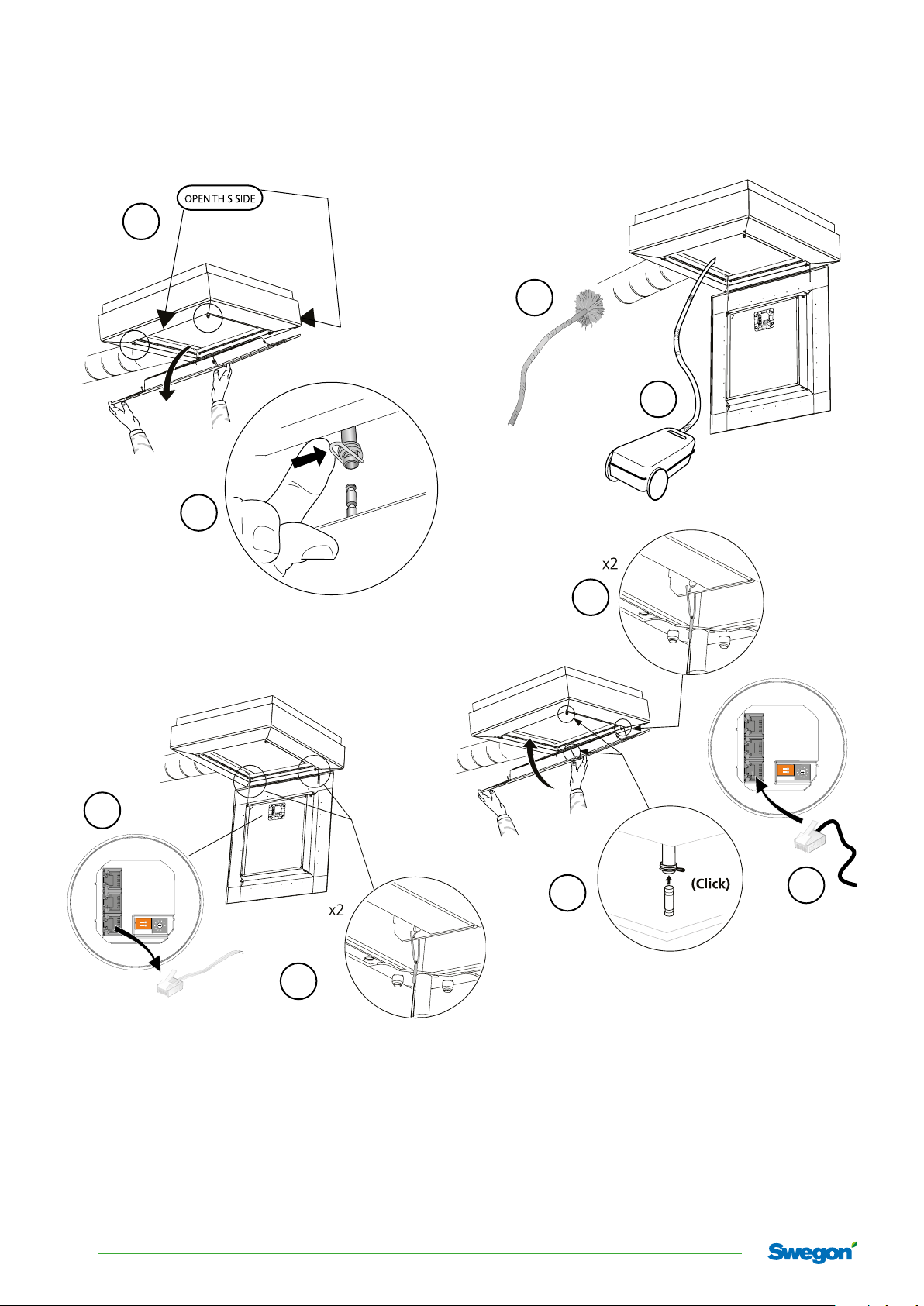
ADAPT Parasol EX
Maintenance
1
5
6
2
7
ON
1 2
3
9
ON
1 2
8
4
12
Swegon reserves the right to alter specications. 20191101
 Loading...